Honda Common Service Manual Motorcycles Motor Scooters ATVs General Repair PDF
Original price was: $95.00.$28.95Current price is: $28.95.
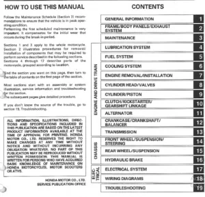
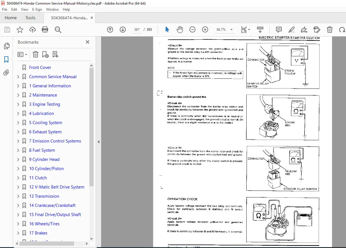
Comprehensive Honda common service manual covering general maintenance and repair procedures applicable across multiple Honda motorcycles, motor scooters, and ATVs. Essential technical documentation includes general safety information, service rules, fastener specifications, ball bearing replacement, maintenance schedules, battery service, brake systems, emission control systems, fuel systems, carburetor service, troubleshooting procedures, and component specifications with detailed illustrations for professional mechanics and DIY enthusiasts.
Description
Honda Common Service Manual Motorcycles Motor Scooters ATVs General Repair – PDF DOWNLOAD
DESCRIPTION
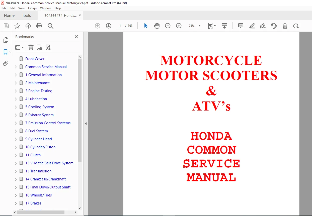
This comprehensive Honda Common Service Manual provides universal maintenance and repair procedures applicable across Honda’s extensive lineup of motorcycles, motor scooters, and ATVs. This essential technical reference manual contains standardized service information, safety protocols, and repair procedures that apply to multiple Honda powersports models, making it an invaluable resource for professional mechanics, dealership technicians, and dedicated DIY enthusiasts.
Document Information
Title: Honda Common Service Manual – Motorcycles, Motor Scooters & ATVs
Format: Scanned from original photocopies (originals no longer in print by Honda)
Distribution: Provided as free technical documentation for Honda service community
Total Pages: 393 pages
Content Type: Universal service procedures and specifications
Note: This manual is distributed freely for the benefit of the Honda service community. The alphabetized index is not available in this version.
Section 1: General Information
General Safety (Pages 1-1 to 1-3)
Carbon Monoxide Hazards:
- WARNING: Exhaust contains poisonous carbon monoxide gas
- Proper ventilation requirements for running engines
- Exhaust evacuation system recommendations for enclosed areas
- Loss of consciousness and death prevention protocols
Gasoline Safety:
- Flammability and explosion hazards under certain conditions
- Work area ventilation requirements
- Keep cigarettes, flames, and sparks away from fuel
- Storage safety protocols
- KEEP OUT OF REACH OF CHILDREN
Battery Hydrogen Gas & Electrolyte:
- Explosive gas emission warnings
- Spark, flame, and cigarette restrictions
- Proper ventilation during charging
- Electrolyte handling (sulfuric acid) safety
- Skin, eye, and clothing contact prevention
- First aid procedures for acid exposure
Nitrogen Pressure (Gas-Filled Shock Absorbers):
- Use ONLY nitrogen for pressurization
- WARNING: Unstable gas can cause fire or explosion
- High-pressure nitrogen hazards
- Disposal procedures: release nitrogen by pressing valve core
- Remove valve stem before disposal
- EPA-compliant oil disposal methods
Hot Components:
- Engine and exhaust system temperature warnings
- Cooling period requirements
- Insulated glove usage recommendations
Service Rules (Pages 1-3 to 1-5)
Tool Requirements:
- Use ONLY metric tools for Honda motorcycles and scooters
- Metric bolts, nuts, and screws NOT interchangeable with English fasteners
- Incorrect tool usage can damage vehicle
- Special tool requirements for specific part removal/installation
Cleaning Procedures:
- Clean exterior before disassembly to prevent contamination
- Wash parts in high-flash-point solvent
- Dry with compressed air
- Protect O-rings and oil seals from cleaning solvents
- Pre-measurement cleaning requirements
Control Cables:
- Must not be bent or distorted
- Proper routing to prevent stiff operation
- Premature cable failure prevention
Rubber Parts:
- Age-related deterioration considerations
- Solvent and oil damage susceptibility
- Pre-reassembly inspection requirements
Ball Bearing Replacement (Pages 1-14 to 1-17)
Bearing Removal Techniques:
- Force application methods (inner/outer race considerations)
- Single race force application damages bearing (must replace)
- Equal force on both races preserves bearing (can reuse)
- Blind hole removal with bearing remover tools
- Thermal expansion method using heat gun for stuck bearings
- WARNING: Wear insulated gloves when handling heated cases
Bearing Removal Tools:
- Bearing remover shaft and head specifications
- Tool compatibility charts for various bearing sizes
- Proper thread engagement requirements
- Replace worn or damaged removers
Bearing Cleaning:
- High flash-point solvent cleaning
- Compressed air drying while holding both races
- WARNING: Do not allow bearing to spin during air drying
- High-speed spinning causes permanent damage
Bearing Inspection:
- Slow rotation test of inner race while holding outer race
- Check for radial play or roughness (replace if present)
- Axial play verification (must have zero axial play)
- Replace if noticeable axial play detected
Bearing Installation:
- ALWAYS install with manufacturer’s name and size code facing OUT
- Applies to open, single-sealed, and double-sealed bearings
- Apply proper grease to open and single-sealed bearings
- Clean bearing recess before installation
- Use driver, attachment, and pilot for outer race installation
- Parallel installation requirement to prevent failure
- CAUTION: Dust in recess or non-parallel installation causes bearing failure
Fasteners (Pages 1-6 to 1-13)
Thread Types – ISO Metric Threads:
Honda motorcycles use International Standards Organization (ISO) metric threads exclusively.
Typical Honda Thread Specifications:
| Diameter (mm) | Pitch (mm) | Diameter (mm) | Pitch (mm) |
|---|---|---|---|
| 3 | 0.6 | 10 | 1.25 |
| 4 | 0.7 | 12 | 1.25 |
| 5 | 0.8 | 14 | 1.5 |
| 6 | 1.0 | 16 | 1.5 |
| 8 | 1.25 | 18 | 1.5 |
Thread Diameter: Outer diameter (O.D.) of male thread or inner diameter (I.D.) across full width of female thread “valley”
Pitch: Thread-to-thread distance that fastener moves in one complete turn
Types of Fasteners and Applications:
Stake-Type Lock Nuts:
- Collar staked (indented) to match shaft groove
- Applications: Clutch center lock nut, wheel bearing retainer, shift drum stopper plate
- Disassembly: Eliminate staking point before loosening
- Assembly: Tighten to specified torque, then stake collar with hammer and punch
- Replace nut if old staked area aligns with shaft groove after torquing
Installation Procedures:
- Bolt/screw lengths vary for each assembly
- Verify correct locations by comparing exposed lengths
- Torquing sequence: Hand-tight all fasteners first
- Torque large fasteners before small fasteners
- Criss-cross pattern from inner-to-outer
- Critical fasteners: torque in 2-3 increments to minimize distortion
- Install clean and dry unless specified otherwise
- Do NOT use oil on threads unless specified
Oil Seals:
- ALWAYS install with grease packed into seal cavity
- Manufacturer’s name faces outside (dry side)
- Verify shaft is smooth and burr-free before installation
- Burrs can damage seal lip
Rubber Hoses (Fuel, Vacuum, Coolant):
- Install with ends bottomed onto fitting
- Allows adequate area for hose clip grip
- Clip grips hose beneath flared end of fitting
Dust/Dirt Boots:
- Replace securely in exact designed positions
- Rubber or plastic boot proper seating critical
Symbol Marks and Abbreviations
Lubrication Symbols:
- Recommended engine oil symbol
- Molybdenum solution (1:1 ratio with engine oil)
- Multi-purpose grease (Lithium-based NLGI #2)
- Molybdenum disulfide grease (3%+ MoS2, NLGI #2)
- Examples: Molykote BR-2 Plus (Dow Corning), Multi-purpose M-2 (Mitsubishi Oil Japan)
- Molybdenum disulfide paste (40%+ MoS2, NLGI #2)
- Examples: Molykote G-n Paste (Dow Corning), Honda Moly 45 (USA), Rocol ASP (UK), Rocol Paste (Sumica Lubricant Japan)
- Silicone grease
- Locking agent (middle strength unless specified)
- Sealant application
- Brake fluid DOT 3 or DOT 4
Service Symbols:
- Replace part(s) with new before assembly
Abbreviations:
- Assy: Assembly
- R: Right (viewed from rear)
- L: Left (viewed from rear)
- I: Intake side/inside
- E: Exhaust side/exterior
- STD: Standard
- OPT: Optional
- OS: Oversized
- rpm: Rotating speed per minute
- BTDC: Before Top Dead Center
- ATDC: After Top Dead Center
- BBDC: Before Bottom Dead Center
- ABDC: After Bottom Dead Center
- AC: Alternating current
- DC: Direct current
- CDI: Capacitive discharge ignition
Installation Direction Marks:
- IN: Install with “IN” toward inside/exhaust side
- TOP: Install with “TOP” toward up (not upside down)
- UP: Install with “UP” toward up (not upside down)
- ▲ (Triangle): Install with mark toward up
- → (Arrow): Install with arrow toward front
- R: Install on right side (viewed from rear)
- L: Install on left side (viewed from rear)
- F (FR): Indicates front side of vehicle
- R (RR): Indicates rear side of vehicle
- OUT (OUTSIDE): Install with letter toward out
- LOWER: Indicates lower level
- UPPER (FULL): Indicates upper level
- Curved Arrow: Indicates rotating direction on rotating parts
Section 2: Maintenance
Battery Service (Pages 2-1 to 2-5)
Fluid Level Checks:
- MPF (Maintenance Free) batteries: No fluid level checks necessary
- Open-type batteries: Regular fluid level inspection required
WARNING:
- Battery fluid (sulfuric acid) causes burning
- Avoid contact with skin, eyes, or clothes
- Emergency wash: Large amounts of water immediately
- Eye exposure: Wash with water and consult physician
Battery Case Inspection:
- Check for cracks in battery case
- White substance (sulfation) on electrodes indicates replacement needed
- Heavy deposits at battery base require replacement
Fluid Level Verification:
- Check each cell against UPPER and LOWER level lines
- Approaching LOWER line: Remove battery, remove filler caps
- Refill to UPPER level with distilled water only
Battery Capacity Testing:
- Use battery tester (preferred method)
- Alternative: Check specific gravity of battery fluid
- CAUTION: Specific gravity difference exceeding 0.01 between cells requires recharging
- Excessive specific gravity difference: Replace battery
NOTE:
- Specific gravity changes approximately 0.007 per 10°C temperature change
- Consider temperature when taking measurements
- Hydrometer fluid level reading taken in horizontal position
Terminal Connection Condition:
- Verify terminals not loose
- Corrosion present: Remove battery, wash rust with warm water
- Use wire brush for complete rust removal
- Reconnect battery and lightly coat terminals with grease
Refer to Section 22 for detailed battery testing and charging procedures
Brake Fluid Service (Pages 2-5 to 2-7)
Leak Detection:
- Firmly apply brake and check for fluid leakage
- Any leakage from brake system: Quickly replace damaged parts
Component Inspection:
- Check hoses, pipes, and joints for degradation and damage
- Verify joints and clamps not loose
- Ensure hoses and pipes don’t contact mechanical parts
- Check clearance during fork turning and vibration
Section 8: Fuel System
Service Information (Page 8-1)
WARNING – Gasoline Hazards:
- Gasoline extremely flammable and explosive under certain conditions
- Work in well-ventilated area
- No smoking, flames, or sparks in work area or storage area
- Fire or explosion risk
CAUTION:
- Bending or twisting control cables impairs smooth operation
- Can cause cables to stick or bind
- Results in loss of vehicle control
- Remove diaphragms before cleaning air and fuel passages with compressed air
- Diaphragms might be damaged by compressed air
Service Procedures:
- Refer to Model Specific manual for carburetor and reed valve removal/installation
- Note O-ring locations during disassembly
- Replace with new O-rings on reassembly
Fuel System Components Covered (Pages 8-1 to 8-24):
- Troubleshooting (Page 8-2)
- System Description (Page 8-3)
- Accelerator Pump (Page 8-7)
- Air Cut-Off Valve (Page 8-7)
- Reed Valve (Page 8-7)
- Fuel Line (Page 8-7)
- Fuel Auto Valve (Page 8-8)
- Carburetor Disassembly/Inspection (Pages 8-9 to 8-14)
- Carburetor Assembly (Pages 8-14 to 8-18)
- Pilot (or Air) Screw Adjustment (Page 8-18)
- Accelerator Pump Adjustment (Page 8-24)
- High Altitude Adjustment (Page 8-24)
Reed Valve Service:
- Remove reed valve covers and reed valves
- Check reeds for damage or fatigue
- Replace if necessary
- Install new reed valve if seat rubber cracked or damaged
- Replace if clearance between reed and seat exists
CAUTION:
- Disassembling or bending reed stopper or reed valve causes damage
- Replace reed valve as complete unit if stopper, reed, or seat faulty
NOTE:
- Certain secondary air supply systems have reed valve built into AiCV
- Refer to Model Specific manual for reed valve location
Section 7: Emission Control Systems
Emission Control Information Labels
- Compliance information
- Adjustment specifications
- Emission control component identification
Key Features & Technical Highlights
✓ Universal Application – Common procedures applicable across Honda motorcycles, scooters, and ATVs
✓ Safety-First Approach – Comprehensive safety warnings for all hazardous operations
✓ Metric Specifications – Complete ISO metric thread and fastener specifications
✓ Professional Illustrations – Detailed diagrams and exploded views
✓ Ball Bearing Service – Complete removal, inspection, and installation procedures
✓ Fastener Technology – Torque specifications and locking device applications
✓ Battery Maintenance – Both MPF and open-type battery service procedures
✓ Brake System Service – Fluid specifications and leak detection protocols
✓ Fuel System Overhaul – Complete carburetor rebuild and adjustment procedures
✓ Emission Controls – Reed valve and air system service procedures
Applicable Honda Models
This common service manual provides universal procedures applicable to:
- Honda motorcycles (all displacements and configurations)
- Honda motor scooters (2-stroke and 4-stroke)
- Honda ATVs (all-terrain vehicles)
- Honda utility vehicles
Note: This manual should be used in conjunction with model-specific service manuals for complete repair and maintenance procedures.
File Details
Manual Name: Honda Common Service Manual – Motorcycles, Motor Scooters & ATVs
Author: A. Morecz
Creation Date: October 11, 2000
Modification Date: April 15, 2003
Total Pages: 393 pages
PDF Quality: Scanned from photocopies (originals no longer printed)
File Size: 7.7 MB
Format: PDF (letter size, 612 x 792 pts)
Distribution: Free technical documentation
Copyright: Honda Motor Company