HP 5316B Service Manual – 100 MHz Universal Counter Repair & Operating PDF
Original price was: $120.00.$18.95Current price is: $18.95.
Complete operating and service manual for HP/Agilent 5316B 100 MHz Universal Counter. Covers frequency, period, time interval, ratio, and totalize measurements from DC to 100 MHz. Includes detailed repair procedures, performance tests, adjustments, troubleshooting flowcharts, schematic diagrams, HP-IB remote programming, and complete specifications. Essential for electronics technicians servicing precision frequency counters in calibration labs, test equipment facilities.
Description
HP 5316B Service Manual – 100 MHz Universal Counter Repair & Operating Guide PDF DOWNLOAD
DESCRIPTION
This comprehensive HP 5316B operating and service manual provides complete technical documentation for electronics technicians and calibration engineers servicing the Hewlett-Packard 5316B 100 MHz Universal Counter. This 182-page professional manual covers all aspects of operation, repair, calibration, and troubleshooting for this precision frequency and time interval measurement instrument.
What This Universal Counter Service Manual Contains
Essential documentation for test equipment technicians, calibration laboratory personnel, and metrology engineers maintaining HP/Agilent frequency counters in electronics manufacturing, aerospace, telecommunications, and standards laboratories.
Complete Section Coverage:
- Section I: General Information – Comprehensive introduction to the HP 5316B universal counter system, complete technical specifications, available options (TCXO, Oven Oscillator, Channel C), safety considerations, instrument identification, recommended accessories, and required test equipment for service and calibration
- Section II: Installation – Detailed setup procedures including:
- Unpacking and inspection protocols
- Power requirements and line voltage selection (100V, 120V, 220V, 240V options)
- Power cable installation procedures
- Operating environment specifications
- Storage and shipment guidelines with proper packaging procedures
- Field Installation of Options – Complete procedures for retrofitting Option 001 TCXO, Option 003 Channel C (50 MHz to 1 GHz), and Option 004 Oven Oscillator with part numbers and installation sequences
- Section III: Operation – Complete operating instructions covering:
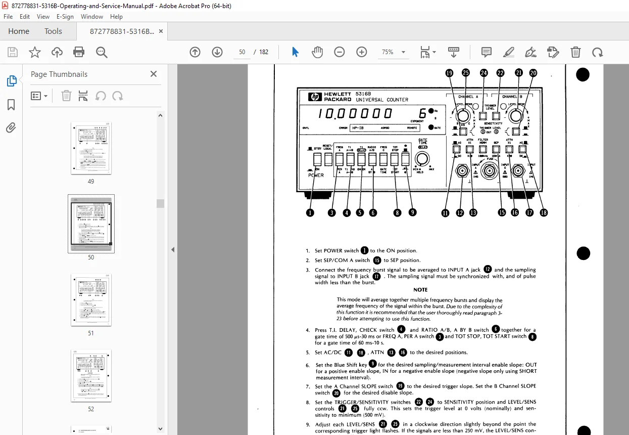
- Front Panel Operation – Detailed explanation of all controls, indicators, and display functions
- Measurement Functions:
- Frequency A Measurements – Range: 0.1 Hz to 100 MHz with 7+ digit resolution
- Period A Measurements – High-resolution period measurement capabilities
- Time Interval Measurements – Dual-channel timing with nanosecond resolution
- Time Interval Average – Statistical averaging for improved accuracy
- Time Interval Delay (Holdoff) – Delayed triggering measurements
- Ratio A/B Measurements – Frequency ratio calculations
- Totalize Function – Event counting with manual or external gating
- Channel C Frequency – Extended 50 MHz to 1 GHz measurements (Option 003)
- Input Amplifier Operation – AC/DC coupling, attenuator settings (×1, ×20), trigger level controls, slope selection, low-pass filtering (100 kHz), and trigger level monitoring
- Remote Programming via HP-IB – Complete IEEE-488 interface documentation including bus compatibility, interface functions, address selection, device commands, input/output formats, programming examples, and special considerations
- Section IV: Performance Tests – Comprehensive verification procedures:
- Operational verification tests for initial checkout
- Complete performance test sequences against published specifications
- Required test equipment specifications (signal generators, frequency standards, DVMs, oscilloscopes)
- Detailed test procedures for all measurement functions
- Accuracy verification at critical frequency points
- HP-IB verification procedures for remote operation testing
- Channel C performance testing (50 MHz to 1 GHz)
- Section V: Adjustments – Precision calibration procedures with detailed instructions:
- A4 Offset Adjustment – Input amplifier DC offset calibration
- Digital-to-Analog Converter Adjustment – DAC linearity calibration
- Trigger Level Gain Compensation – Trigger circuit calibration
- Injection-Locked Multiplier Adjustment – High-frequency converter alignment
- Internal Time Base Adjustment – Crystal oscillator frequency calibration
- Option 001 TCXO Adjustment – Temperature-compensated oscillator calibration
- Option 004 Oven Oscillator Adjustment – High-stability oven oscillator alignment
- Channel C Adjustments – Extended frequency range calibration (50 MHz – 1 GHz)
- All adjustments include location diagrams, required equipment, and step-by-step procedures
- Section VI: Service – Complete troubleshooting and repair documentation:
- Theory of Operation – Detailed circuit analysis with signal flow descriptions, block diagrams, and functional explanations of all subsystems
- Troubleshooting Procedures:
- Systematic troubleshooting flowcharts
- Preliminary troubleshooting guides
- Main counter troubleshooting sequences
- HP-IB remote control troubleshooting
- Signature Analysis Troubleshooting – Advanced digital circuit diagnostic techniques
- Recommended Test Equipment – Specified instruments for troubleshooting and repair
- Schematic Diagram Notes – Complete component reference designations and board identification
- Safety Considerations – Critical warnings for service technicians
- Service Aids – Pozidriv screwdriver requirements, test points on PCBs, and diagnostic access points
- Complete Schematic Diagrams – Full engineering drawings including:
- Overall block diagram showing signal paths
- A1 Motherboard schematic (2 sheets with complete digital logic)
- A2/A4 Input Assembly detailed schematics
- A3 Channel C Assembly circuits (Option 003)
- A7 Time Base Assembly schematics (standard, TCXO, and oven oscillator variants)
- Digital-to-Analog Converter assembly (U26)
- Detailed component layouts and interconnections
Technical Specifications Covered
Input Characteristics (Channels A & B):
- Frequency Range: DC to 100 MHz (AC coupled: 30 Hz to 100 MHz)
- Sensitivity: 10 mV RMS sine wave to 10 MHz, 25 mV RMS to 100 MHz, 75 mV p-p pulse (5 ns minimum width)
- Dynamic Range: 30 mV to 5V p-p (0-10 MHz), 75 mV to 5V p-p (10-100 MHz)
- Signal Operating Range: +2.5V DC to -2.5V DC
- Coupling: AC or DC, switchable
- Input Impedance: 1 MΩ nominal shunted by <40 pF
- Attenuator: ×1 or ×20 nominal, switchable
- Trigger Level: Variable +2.5V to -2.5V DC
- Slope Selection: Independent positive or negative
- Low-Pass Filter: 100 kHz, 3 dB point (Channel A only)
Frequency Measurement:
- Range: 0.1 Hz to 100 MHz
- Resolution: 7+ digits per second of gate time (10 Hz to 1 nHz LSD)
- Accuracy: ±Resolution ± (time base error × frequency)
Period Measurement:
- High-resolution period determination with reciprocal counting techniques
Time Interval Measurement:
- Resolution: Nanosecond-level timing resolution
- Channels: Dual independent channels with separate trigger controls
- Modes: Single-shot, average, and delay (holdoff) measurements
Ratio Measurement:
- Range: 0.1 Hz to 100 MHz on both channels
- Applications: Frequency comparison, crystal testing, oscillator characterization
Channel C (Option 003):
- Extended Range: 50 MHz to 1 GHz frequency measurements
- Injection-Locked Multiplier: For high-frequency signal processing
Time Base Options:
- Standard: Crystal oscillator
- Option 001 TCXO: Temperature-compensated crystal oscillator for improved stability
- Option 004 Oven Oscillator: Precision oven-controlled oscillator for laboratory standards
General Specifications:
- Display: 8-digit LED display with engineering notation
- Remote Control: HP-IB (IEEE-488) interface standard
- Mounting: Rack mount or bench configuration
- Power: Multiple line voltage options (100V, 120V, 220V, 240V)
Essential for Test Equipment Professionals
This HP universal counter service manual is specifically designed for:
✓ Electronics calibration laboratories and metrology departments
✓ Test equipment repair technicians and depot service facilities
✓ Aerospace and defense equipment maintenance personnel
✓ Telecommunications test equipment engineers
✓ Contract electronics manufacturers with calibration facilities
✓ University and research laboratory technical staff
✓ Standards laboratories maintaining frequency/time measurement equipment
✓ RF and microwave test facility technicians
Applications & Industries
The HP 5316B universal counter serves critical measurement needs in:
- Electronics Manufacturing – Production testing, quality control, and incoming inspection
- Calibration Laboratories – Secondary frequency standards and precision measurements
- Aerospace/Defense – Radar testing, communications equipment verification
- Telecommunications – Clock testing, timing system verification
- Research & Development – Precision frequency and time interval measurements
- Education – Electronics training laboratories and technical schools
- Service Centers – Test equipment calibration and repair facilities
Measurement Capabilities in Detail
Frequency Measurements:
- Continuous frequency measurement from DC to 100 MHz
- Automatic ranging with engineering notation display
- Gate times selectable for resolution optimization
- Prescaling for extended range measurements
Time Interval Measurements:
- Start/Stop timing between Channel A and Channel B
- Resolution to nanoseconds with proper signal conditioning
- Average mode for noise reduction and improved accuracy
- Delay mode for holdoff triggering applications
Remote Programming (HP-IB):
- Full IEEE-488 bus compatibility
- Programmable measurement functions
- Data output formatting options
- Address selection via rear panel DIP switches
- Front panel HP-IB status LED indicators
- Complete command set documentation with examples
Professional Service Documentation Features
This manual includes:
- 182 Pages of comprehensive technical content
- Exploded Assembly Diagrams for component identification
- Schematic Diagrams with complete component values
- Block Diagrams showing signal flow and functional relationships
- Troubleshooting Flowcharts for systematic fault isolation
- Adjustment Procedures with precise equipment requirements
- Parts Lists with HP part numbers for ordering
- Signal Mnemonics for logic analyzer troubleshooting
- Signature Analysis Data for advanced digital diagnostics
- Performance Test Limits for specification verification
Certification & Traceability
HP certification documentation included:
- Factory calibration traceability to NIST (National Bureau of Standards)
- International Standards Organization (ISO) member calibration facilities
- One-year warranty details from date of shipment
- Quality assurance and manufacturing standards
Safety & Compliance
- Safety Class I instrument (protective earth terminal)
- Detailed safety considerations for service personnel
- Proper grounding requirements
- Safety symbol explanations and warnings
- Voltage selection and fuse requirements
Historical Context
Originally manufactured by Hewlett-Packard (now Agilent Technologies), the HP 5316B represents professional-grade frequency and time interval measurement equipment from the 1980s era. This manual applies to instruments with Serial Prefix 2708A manufactured through September 1987.
Manual Details
HP Part Numbers:
- Manual Part Number: 05316-90014
- Microfiche Part Number: 05316-90015
- Print Date: September 1987
Perfect for frequency counter calibration, precision time interval measurement, and HP-IB remote control programming, this technical manual provides essential documentation for maintaining critical test and measurement equipment used in electronics laboratories, calibration facilities, and production test environments worldwide.
FILE DETAILS
Manual Name: HP 5316B Operating and Service Manual
Equipment Covered: HP/Agilent 5316B 100 MHz Universal Counter
Serial Prefix: 2708A
Manufacturer: Hewlett-Packard Company (now Agilent Technologies)
Year: September 1987
Manual Quality: Very Good – Scanned original with readable text, complete schematics, diagrams, and technical illustrations
Total Pages: 182