HSU-18 HSU-22 HVA103 R2 DB Air Conditioner Service Repair Manual PDF Download
Original price was: $85.00.$13.95Current price is: $13.95.
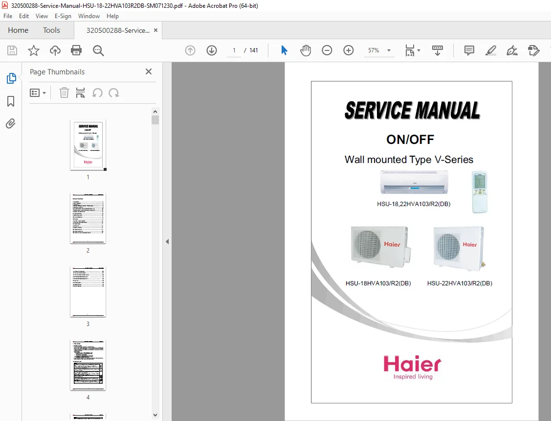
Complete factory service manual for HSU-18HVA103/R2(DB) and HSU-22HVA103/R2(DB) wall-mounted air conditioner systems. Comprehensive 141-page technical documentation with detailed repair procedures, wiring diagrams, circuit diagrams, troubleshooting guides, and complete disassembly instructions. Covers both 18,000 and 22,000 BTU split-type cooling and heating units with R-410A/R22 refrigerant specifications.
Description
HSU-18 HSU-22 HVA103 R2 DB Air Conditioner Service Repair Manual PDF Download
FILE DETAILS
| Detail | Information |
|---|---|
| Manual Name | HSU-18,22HVA103/R2(DB) Domestic Air Conditioner Service Manual |
| Models Covered | HSU-18HVA103/R2(DB) (18,000 BTU), HSU-22HVA103/R2(DB) (22,000 BTU) |
| Year | 2007 (Document: SM071230) |
| Pages | 141 pages |
| PDF Quality | High quality – factory original with diagrams |
| Language | English |
| File Size | 8.5 MB |
DESCRIPTION
Factory Service Manual for HSU-18/22 HVA103/R2(DB) Split Air Conditioner Systems
This comprehensive HSU air conditioner service manual provides complete factory-level technical documentation for professional HVAC technicians servicing wall-mounted split-type air conditioning systems. Essential repair guide covering both 18,000 BTU and 22,000 BTU cooling and heating units.
Complete Model Coverage:
HSU-18HVA103/R2(DB)
- Cooling capacity: 18,000 BTU/h
- Heating capacity with heat pump
- Wall-mounted split system
HSU-22HVA103/R2(DB)
- Cooling capacity: 22,000 BTU/h
- Heating capacity with heat pump
- Wall-mounted split system
Technical Specifications Covered:
Refrigerant Systems:
- R-410A refrigerant compatible
- R22 refrigerant compatible
- Complete refrigerant charging procedures
- Leak detection and repair protocols
Operating Temperature Ranges:
- Cooling Mode Indoor: 18°C to 32°C (DB/WB 32°C/23°C max, 18°C/14°C min)
- Heating Mode Indoor: 15°C to 27°C maximum
- Cooling Mode Outdoor: -7°C to 43°C (DB/WB 43°C/26°C max)
- Heating Mode Outdoor: -7°C/-8°C to 24°C/18°C (DB/WB)
System Components:
- Indoor unit (wall-mounted type)
- Outdoor unit (condensing unit)
- Remote controller with multiple functions
- Electronic control boards
- Inverter technology
Comprehensive Manual Contents:
1. Introduction (Pages 3-7)
- Safety cautions and warnings
- Repair work safety procedures
- Electrical safety guidelines
- Refrigerant handling precautions
- Grounding requirements
- Capacitor discharge procedures
- Post-repair inspection requirements
- Icon usage and symbols explanation
2. List of Functions (Page 8)
- Complete feature overview
- Operating mode descriptions
- Control functions catalog
3. Specifications (Pages 9-10)
- Detailed technical specifications
- Ambient temperature ranges
- Power supply requirements
- Performance ratings
- Electrical characteristics
4. Printed Circuit Board Connector Wiring Diagrams (Pages 11-19)
- PCB connection diagrams
- Connector pin assignments
- Wire color coding
- Terminal identification
- Signal path documentation
5. Functions and Control (Pages 20-47)
- 5.1 Main functions and control specifications of indoor unit
- Cooling mode operation
- Heating mode operation
- Dehumidification (dry) mode
- Fan speed control
- Auto mode operation
- DASH operation sequences
- Temperature adjustment levels
- Timer functions
- Sleep mode operation
- Swing motor control
- Display functions
- 5.2 Main functions and control specifications of outdoor unit
- Compressor frequency control
- Inverter operation
- Defrost cycle operation
- Fan motor control
- Protection functions
- 5.3 Function of main thermistors
- Room temperature sensor
- Evaporator temperature sensor
- Condenser temperature sensor
- Outdoor ambient sensor
- Discharge temperature sensor
- 5.4 Value of thermistors with resistance tables
6. System Configuration (Pages 48-74)
- 6.1 Complete system configuration diagrams
- 6.2 Detailed component instructions
- Compressor specifications
- Fan motor details
- Expansion valve operation
- Four-way valve function
- Capacitor specifications
- Control board layouts
7. Error Codes and Description (Pages 75-89)
- 7.1 Problem symptoms and measures
- No operation troubleshooting
- Poor cooling/heating diagnosis
- Abnormal noise identification
- Water leakage issues
- Display error interpretation
- 7.2 Comprehensive troubleshooting flowcharts
- Systematic diagnostic procedures
- Component testing methods
- Voltage and current measurements
- Resistance measurements
- Pressure readings
- Temperature verification
8. Installation Instructions (Pages 90-97)
- Indoor unit mounting procedures
- Outdoor unit placement guidelines
- Refrigerant piping installation
- Electrical connection procedures
- Drain pipe installation
- Insulation requirements
- Leak testing procedures
- Vacuum pump operation
- Refrigerant charging methods
- Test run procedures
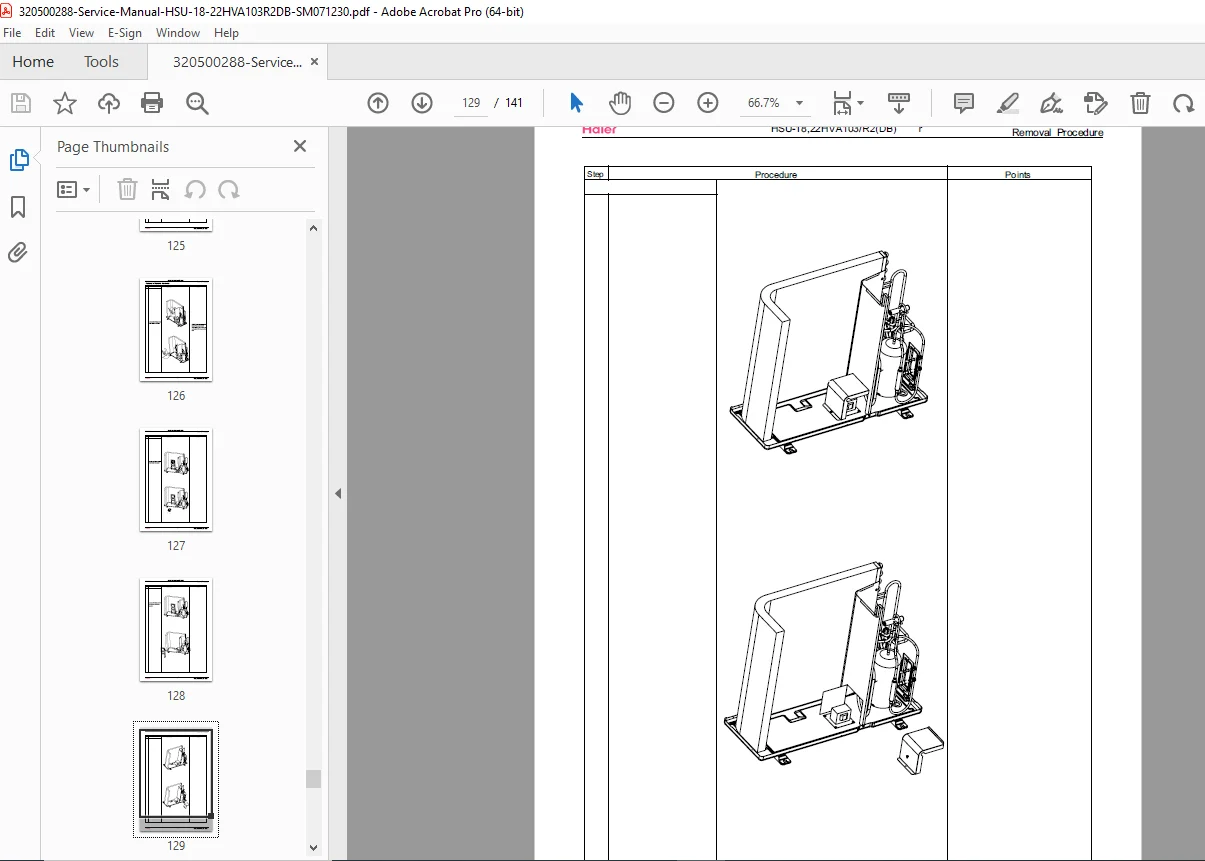
9. Removal Procedures (Pages 98-109)
- 9.1 Air filter removal and cleaning
- 9.2 Front grille disassembly
- 9.3 Vertical blades and swing motor removal
- 9.4 Electrical box removal
- 9.5 Heat exchanger (evaporator) removal
- 9.6 Fan rotor and fan motor removal
- Step-by-step photos and diagrams
- Screw location identification
- Reassembly notes
HSU-18HVA103/R2(DB) Outdoor Unit (Pages 110-119)
- Complete outdoor unit disassembly
- Compressor removal procedures
- Fan motor and blade removal
- Four-way valve replacement
- Capacitor replacement
- PCB removal and replacement
- Refrigerant line disconnection
- Component location diagrams
HSU-22HVA103/R2(DB) Outdoor Unit (Pages 120-132)
- 22,000 BTU specific procedures
- Component variations
- Enhanced capacity specifications
- Larger compressor service
- Additional cooling capacity components
10. Appendix (Pages 133-141)
- 10.1 Piping diagrams
- Refrigerant flow schematics
- Cooling cycle diagrams
- Heating cycle diagrams
- Four-way valve operation
- 10.2 Wiring diagrams
- Indoor unit wiring
- Outdoor unit wiring
- Inter-unit connection diagrams
- Power supply wiring
- Control wiring
- 10.3 Circuit diagrams
- Complete electronic schematics
- PCB circuit layouts
- Component identification
- Test point locations
Key Safety Information Included:
- Electrical Safety:
- Power disconnection procedures
- Capacitor discharge requirements
- Wet hands prohibition warnings
- Grounding requirements
- Leakage breaker installation
- Refrigerant Safety:
- R-410A/R22 handling procedures
- Gas leak detection methods
- Ventilation requirements
- Toxic gas prevention
- Proper refrigerant disposal
- Recovery and recycling
- Mechanical Safety:
- High-speed fan warnings
- Hot surface cautions
- Heavy equipment handling
- Proper lifting techniques
- Installation stability requirements
Advanced Diagnostic Features:
- Error code display and interpretation
- LED indicator troubleshooting
- Remote controller diagnostics
- Compressor frequency monitoring
- Temperature sensor verification
- Pressure switch testing
- Thermal protection device testing
- Component continuity testing
Professional Repair Procedures:
- Compressor replacement with vacuum and charging
- PCB board diagnosis and replacement
- Fan motor testing and replacement
- Capacitor testing and replacement
- Thermistor calibration and replacement
- Four-way valve operation verification
- Expansion valve service
- Refrigerant leak repair procedures
- Brazing and soldering techniques
Why This Manual is Essential:
This air conditioner repair manual provides complete factory documentation for professional HVAC service technicians. With detailed wiring diagrams, circuit schematics, comprehensive troubleshooting procedures, and step-by-step disassembly instructions, you’ll have everything needed for efficient air conditioning system repair.
Perfect for:
- Professional HVAC technicians
- Air conditioning service centers
- Refrigeration specialists
- Building maintenance professionals
- Technical training institutions
- Commercial facility managers
- Property management companies
Covers All Essential Repairs:
- Split system installation and commissioning
- Cooling system troubleshooting
- Heating system diagnosis
- Electrical component replacement
- Refrigerant system service
- Indoor unit maintenance
- Outdoor unit repairs
- Remote controller programming
DOWNLOAD INSTANTLY AND START REPAIRS TODAY! Get immediate access to this complete 141-page factory service manual. Professional HVAC documentation with detailed diagrams, error codes, and repair procedures trusted by technicians worldwide!
Reasoning
- 141-page comprehensive service manual
- Covers two capacity models (18K and 22K BTU)
- Complete technical documentation with diagrams
- HVAC professional audience
- Both indoor and outdoor unit coverage
- Wiring, piping, and circuit diagrams included
- Error codes and troubleshooting procedures
- Moderate page count for HVAC manuals