Husqvarma 701 Enduro 2021 Repair Manual – PDF DOWNLOAD
$29.95
Husqvarma 701 Enduro 2021 Repair Manual – PDF DOWNLOAD
Description
Husqvarma 701 Enduro 2021 Repair Manual – PDF DOWNLOAD
FILE DETAILS:
Husqvarma 701 Enduro 2021 Repair Manual – PDF DOWNLOAD
Language : English
Pages : 406
Downloadable : Yes
File Type : PDF
IMAGES PREIVEW OF THE MANUAL:
TABLE OF CONTENTS:
Husqvarma 701 Enduro 2021 Repair Manual – PDF DOWNLOAD
Table of Contents
1. Means of Representation
1.1 Symbols Used
1.2 Formats Used
2. Safety Advice
2.1 Repair Manual
2.2 Safety Advice
2.3 Degrees of Risk and Symbols
2.4 Work Rules
3. Important Notes
3.1 Manufacturer Warranty and Implied Warranty
3.2 Fuel and Auxiliary Substances
3.3 Spare Parts and Husqvarna Motorcycles Technical Accessories
3.4 Figures
4. Serial Numbers
4.1 Vehicle Identification Number
4.2 Type Label
4.3 Engine Number
4.4 Key Number
4.5 Fork Part Number
4.6 Shock Absorber Article Number
5. Motorcycle
5.1 Raising the Motorcycle with Rear Lifting Gear
5.2 Removing the Rear of the Motorcycle from the Lifting Gear
5.3 Raising the Motorcycle with a Lift Stand
5.4 Removing the Motorcycle from the Lift Stand
5.5 Raising the Motorcycle with a Work Stand
5.6 Removing the Motorcycle from the Work Stand
5.7 Starting the Vehicle
5.8 Starting the Motorcycle to Check Function
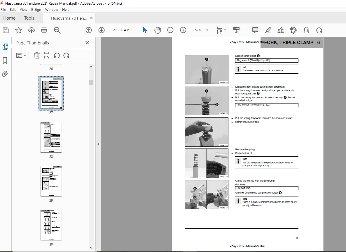
6. Fork, Triple Clamp
6.1 Adjusting the Compression Damping of the Fork
6.2 Adjusting the Rebound Damping of the Fork
6.3 Bleeding the Fork Legs
6.4 Cleaning the Dust Boots of the Fork
6.5 Removing the Fork Protector
6.6 Installing the Fork Protector
6.7 Removing the Fork Legs
6.8 Installing the Fork Legs
6.9 Servicing the Fork
6.10 Disassembling the Fork Legs
6.11 Disassembling the Cartridge
6.12 Disassembling the Tap Compression
6.13 Checking the Fork Legs
6.14 Assembling the Tap Compression
6.15 Assembling the Cartridge
6.16 Assembling the Fork Legs
6.17 Checking the Steering Head Bearing Play
6.18 Adjusting the Steering Head Bearing Play
6.19 Removing the Lower Triple Clamp
6.20 Installing the Lower Triple Clamp
6.21 Changing the Steering Head Bearing
7. Handlebar, Controls
7.1 Handlebar Position
7.2 Adjusting the Handlebar Position
7.3 Changing the Throttle Grip
8. Frame
8.1 Removing the Engine Guard
8.2 Installing the Engine Guard
8.3 Checking the Frame
9. Shock Absorber, Link Fork
9.1 Adjusting the High-Speed Compression Damping of the Shock Absorber
9.2 Adjusting the Low-Speed Compression Damping of the Shock Absorber
9.3 Adjusting the Rebound Damping of the Shock Absorber
9.4 Measuring the Rear Wheel Dimension (Unloaded)
9.5 Checking the Static Sag of the Shock Absorber
9.6 Checking the Riding Sag of the Shock Absorber
9.7 Adjusting the Riding Sag
9.8 Adjusting the Spring Preload of the Shock Absorber
9.9 Checking the Heim Joint for Play
9.10 Removing the Shock Absorber
9.11 Installing the Shock Absorber
9. Shock Absorber, Link Fork (continued)
9.12 Checking the Shock Absorber Linkage
9.13 Servicing the Shock Absorber
9.14 Removing the Spring
9.15 Disassembling the Damper
9.16 Disassembling the Piston Rod
9.17 Disassembling the Rebound Adjustor
9.18 Checking the Damper
9.19 Changing the Heim Joint
9.20 Changing the Silent Block
9.21 Assembling the Rebound Adjustor
9.22 Assembling the Piston Rod
9.23 Assembling the Damper
9.24 Bleeding and Filling the Damper
9.25 Filling the Damper with Nitrogen
9.26 Installing the Spring
9.27 Checking the Swingarm
9.28 Checking the Fork Bearing for Play
9.29 Removing the Link Fork
9.30 Installing the Link Fork
9.31 Changing the Link Fork Bearing
10. Exhaust System
10.1 Removing the Manifold
10.2 Installing the Manifold
10.3 Removing the Main Silencer
10.4 Installing the Main Silencer
11. Air Filter
11.1 Removing the Air Filter
11.2 Installing the Air Filter
11.3 Removing the Air Filter Box
11.4 Installing the Air Filter Box
11.5 Changing the Air Filter and Cleaning the Air Filter Box
12. Fuel Tank, Seat, Trim
12.1 Opening the Fuel Tank Filler Cap
12.2 Closing the Fuel Tank Filler Cap
12.3 Removing the Seat
12.4 Mounting the Seat
12.5 Removing the Side Cover
12.6 Mounting the Side Cover
12.7 Removing the Rear Right Side Cover
12.8 Installing the Rear Right Side Cover
12.9 Removing the Rear Left Side Cover
12.10 Installing the Rear Left Side Cover
12.11 Removing the Rear Fairing
12.12 Installing the Rear Fairing
12.13 Checking the Fuel Pressure
12.14 Changing the Fuel Screen
12.15 Changing the Fuel Filter
12.16 Changing the Fuel Pump
13. Mask, Fender
13.1 Removing the Front Fender
13.2 Installing the Front Fender
14. Wheels
14.1 Checking Tire Pressure
14.2 Checking Tire Condition
14.3 Checking the Wheel Bearing for Play
14.4 Checking the Brake Discs
14.5 Checking Spoke Tension
14.6 Checking the Rim Run-Out
14.7 Front Wheel
14.7.1 Removing the Front Wheel
14.7.2 Installing the Front Wheel
14.7.3 Removing the Front Wheel with the Work Stand
14.7.4 Installing the Front Wheel with the Work Stand
14.7.5 Changing the Front Brake Disc
14.7.6 Changing the Front Wheel Bearing
14.8 Rear Wheel
14.8.1 Removing the Rear Wheel
14.8.2 Installing the Rear Wheel
14.8.3 Removing the Rear Wheel with the Work Stand
14.8.4 Installing the Rear Wheel with the Work Stand
14.8.5 Changing the Rear Wheel Bearing
14.8.6 Changing the Bearing of the Rear Sprocket Carrier
14.8.7 Changing the Rear Brake Disc
14.8.8 Checking the Chain Tension
14.8.9 Adjusting the Chain Tension
14.8.10 Adjusting the Chain Guide
14.8.11 Checking the Chain, Rear Sprocket, Engine Sprocket, and Chain Guide
14.8.12 Opening the Chain
14.8.13 Riveting the Chain
14.8.14 Cleaning the Chain
14.8.15 Checking the Rear Hub Damping Rubber Pieces
14.8.16 Changing the Drivetrain Kit
15. Wiring Harness, Battery
15.1 Removing the 12V Battery
16. Brake System
16.1 Anti-lock Braking System (ABS)
16.2 Checking the Front Brake Linings
16.3 Changing the Front Brake Linings
16.4 Adjusting the Basic Position of the Hand Brake Lever
16.5 Checking the Front Brake Fluid Level
16.6 Adding Front Brake Fluid
16.7 Changing the Front Brake Fluid
16.8 Checking the Rear Brake Linings
16.9 Changing the Rear Brake Linings
16.10 Checking the Free Travel of the Foot Brake Lever
16.11 Adjusting the Basic Position of the Foot Brake Lever
16.12 Checking the Rear Brake Fluid Level
16.13 Adding Rear Brake Fluid
16.14 Changing the Rear Brake Fluid
17. Lighting System, Instruments
17.1 Combination Instrument
17.1.1 Overview
17.1.2 Activation and Test
17.1.3 Setting the Combination Instrument
17.1.4 Setting Kilometers or Miles
17.1.5 Setting the Clock
17.1.6 Setting the Service Interval
17.1.7 Tachometer
17.1.8 Odometer
17.1.9 Gear Display
17.1.10 Service Display
17.1.11 Distance Fuel Reserve
17.2 Checking the Headlight Setting
17.3 Adjusting the Headlight Range
17.4 Removing the Headlight Mask with Headlight
17.5 Installing the Headlight Mask with Headlight
17.6 Changing the Position Light Lamp
17.7 Changing the Headlight Bulb
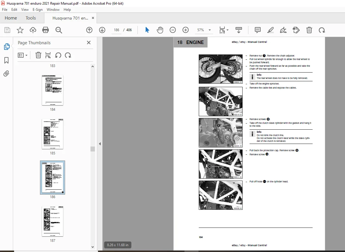
18. Engine
18.1 Removing the Engine
18.2 Installing the Engine
18.3 Engine Disassembly
18.3.1 Clamping the Engine into the Work Stand
18.3.2 Removing the Front Resonator
18.3.3 Draining the Engine Oil
18.3.4 Removing the Clutch Push Rod
18.3.5 Removing the Starter Motor
18.3.6 Removing the Spark Plugs
18.3.7 Removing the Valve Cover
18.3.8 Removing the Alternator Cover
18.3.9 Removing the Spacer
18.3.10 Removing the Gear Position Sensor
18.3.11 Removing the Oil Filter
18.3.12 Removing the Thermostat
18.3.13 Positioning the Engine at Ignition Top Dead Center
18.3.14 Removing the Timing Chain Tensioner
18.3.15 Removing the Camshafts
18.3.16 Removing the Cylinder Head
18.3.17 Removing the Piston
18.3.18 Removing the Water Pump Impeller
18.3.19 Removing the Rotor
18.3.20 Removing the Timing Chain
18.3.21 Removing the Crankshaft Speed Sensor
18.3.22 Removing the Shift Shaft Sensor
18.3.23 Removing the Clutch Cover
18.3.24 Removing the Clutch Basket
18.3.25 Removing the Primary Gear Wheel
18.3.26 Removing the Starter Drive
18.3.27 Removing the Shift Shaft
18.5.28 Installing the Spacer
18.5.30 Installing the Valve Cover
18.5.31 Installing the Spark Plugs
18.5.32 Installing the Starter Motor
18.5.33 Installing the Clutch Push Rod
18.5.34 Installing the Oil Screens
18.5.35 Installing the Resonator
18.5.36 Removing the Engine from the Work Stand
19. Clutch
19.1 Checking/Correcting the Fluid Level of the Hydraulic Clutch
19.2 Changing the Hydraulic Clutch Fluid
19.3 Checking the Clutch
20. Shift Mechanism
20.1 Changing the Gear Position Sensor
20.2 Programming the Gear Position Sensor
20.3 Changing the Shift Shaft Sensor
20.4 Programming the Shift Shaft Sensor
21. Water Pump, Cooling System
21.1 Draining the Coolant
21.2 Filling/Bleeding the Cooling System
21.3 Changing the Coolant
21.4 Checking the Antifreeze and Coolant Level
21.5 Checking the Coolant Level
22. Lubrication System
22.1 Oil Circuit
22.2 Checking/Cleaning the Oil Nozzle for Clutch Lubrication
22.3 Checking the Engine Oil Level
22.4 Checking the Oil Pressure
22.5 Changing the Engine Oil and Oil Filter, Cleaning the Oil Screens
22.6 Adding Engine Oil
23. Ignition System
23.1 Checking the Alternator Stator Winding
23.2 Checking the Ignition Coil Primary Winding
23.3 Changing the Spark Plugs
24. Cylinder Head
24.1 Checking the Valve Clearance
24.2 Adjusting the Valve Clearance
25. Throttle Valve Body
25.1 Performing the Initialization Run
25.2 Resetting the Engine Electronics Control Unit
26. Technical Data
26.1 Engine Specifications
26.2 Tolerance and Engine Wear Limits
26.3 Engine Tightening Torques
26.4 Capacities
26.4.1 Engine Oil
26.4.2 Coolant
26.4.3 Fuel
26.5 Chassis Specifications
26.6 Electrical System26.6.1 ACC1 and ACC2
26.6.2 Diagnostics Connector
26.7 Transmission
26.8 Fork
26.9 Shock Absorber
26.10 Chassis Tightening Torques
27. Cleaning/Protective Treatment
27.1 Cleaning the Motorcycle
27.2 Checks and Maintenance for Winter Operation
28. Storage
28.1 Storage Preparation
28.2 Preparing for Use After Storage
29. Service Schedule
29.1 Additional Information
29.2 Required Work
29.3 Recommended Work
30. Wiring Diagram
30.1 Page 01 of 11
30.2 Page 02 of 11
30.3 Page 03 of 11
30.4 Page 04 of 11
DESCRIPTION:
Husqvarma 701 Enduro 2021 Repair Manual – PDF DOWNLOAD
INTRODUCTION:
Modify or delete technical specifications, prices, colors, forms, materials, services, designs, and equipment without prior notice and without providing reasons.
Adapt features to local conditions.
Discontinue the production of specific models without prior notice.
G.B 03/01/25