Hyster A216 (J2.00-3.20XM) Service Manual – PDF DOWNLOAD
Original price was: $98.95.$29.95Current price is: $29.95.
Hyster A216 (J2.00-3.20XM) Service Manual – PDF DOWNLOAD
Description
Hyster A216 (J2.00-3.20XM) Service Manual – PDF DOWNLOAD
DESCRIPTION:
Hyster A216 (J2.00-3.20XM) Service Manual – PDF DOWNLOAD
SAFETY PRECAUTIONS MAINTENANCE AND REPAIR
• When lifting parts or assemblies, make sure all slings, chains, or cables are correctly
fastened, and that the load being lifted is balanced. Make sure the crane, cables, and
chains have the capacity to support the weight of the load.
• Do not lift heavy parts by hand, use a lifting mechanism.
• Wear safety glasses.
• DISCONNECT THE BATTERY CONNECTOR before doing any maintenance or repair
on electric lift trucks. Disconnect the battery ground cable on internal combustion lift
trucks.
• Always use correct blocks to prevent the unit from rolling or falling. See HOW TO PUT
THE LIFT TRUCK ON BLOCKS in the Operating Manual or the Periodic Maintenance
section.
• Keep the unit clean and the working area clean and orderly.
• Use the correct tools for the job.
• Keep the tools clean and in good condition.
• Always use HYSTER APPROVED parts when making repairs. Replacement parts
must meet or exceed the specifications of the original equipment manufacturer.
• Make sure all nuts, bolts, snap rings, and other fastening devices are removed before
using force to remove parts.
• Always fasten a DO NOT OPERATE tag to the controls of the unit whenmaking repairs,
or if the unit needs repairs.
• Be sure to follow the WARNING and CAUTION notes in the instructions.
• Gasoline, Liquid Petroleum Gas (LPG), Compressed Natural Gas (CNG), and Diesel fuel
are flammable. Be sure to follow the necessary safety precautions when handling these
fuels and when working on these fuel systems.
• Batteries generate flammable gas when they are being charged. Keep fire and sparks
away from the area. Make sure the area is well ventilated.
TABLE OF CONTENTS:
Hyster A216 (J2.00-3.20XM) Service Manual – PDF DOWNLOAD
0620SRM294-897076-(08-2003)-EN.............................................................................................................. 1
toc..................................................................................................................................... 1
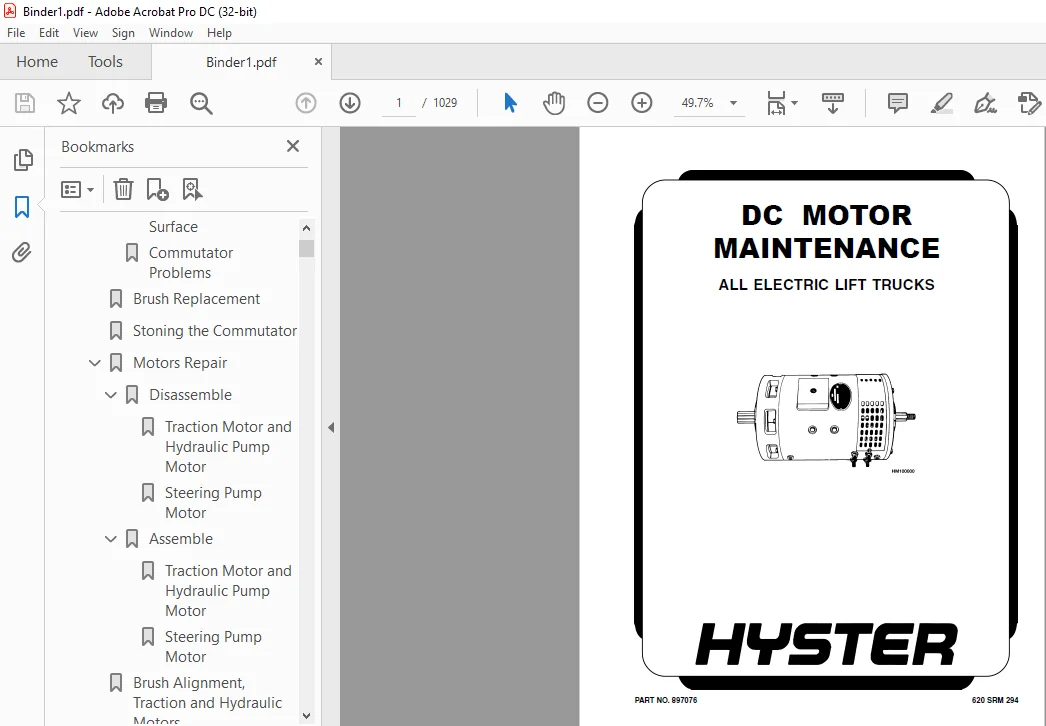
DC Motor Maintenance................................................................................................................ 1
Safety Precautions Maintenance and Repair........................................................................................... 2
General............................................................................................................................. 5
Brush and Commutator Inspection..................................................................................................... 5
Hydraulic Pump Motor and Traction Motor......................................................................................... 5
Steering Pump Motor............................................................................................................. 8
Normal Commutator Surface....................................................................................................... 8
Commutator Problems............................................................................................................. 8
Brush Replacement................................................................................................................... 12
Stoning the Commutator.............................................................................................................. 14
Motors Repair....................................................................................................................... 16
Disassemble..................................................................................................................... 16
Traction Motor and Hydraulic Pump Motor..................................................................................... 16
Steering Pump Motor......................................................................................................... 20
Assemble........................................................................................................................ 20
Traction Motor and Hydraulic Pump Motor..................................................................................... 20
Steering Pump Motor......................................................................................................... 21
Brush Alignment, Traction and Hydraulic Motors...................................................................................... 24
Tests for Damaged Field and Armature................................................................................................ 24
Test for an Open Circuit in Armature............................................................................................ 24
Test for Short Circuit in One Armature Winding.................................................................................. 25
Test for Short Circuit to Armature Shaft........................................................................................ 25
Test for Open Circuit in Field Coil............................................................................................. 25
Test for Short Circuit in Field Coil............................................................................................ 25
Test for Short Circuit between Field and Motor Case............................................................................. 26
Brush Holder Test............................................................................................................... 26
Troubleshooting..................................................................................................................... 26
tables.................................................................................................................................. 1
Table 1. Normal Commutator Surfaces................................................................................................. 7
Table 2. Commutator Problems........................................................................................................ 8
Table 3. Brush Wear Replacement Guide............................................................................................... 12
1400SRM575-897670(03-2003)-EN............................................................................................................... 31
toc..................................................................................................................................... 31
Drive Axle, Speed Reducer, and Differential......................................................................................... 31
Safety Precautions Maintenance and Repair........................................................................................... 32
General............................................................................................................................. 35
Description......................................................................................................................... 35
Drive Axle, Speed Reducer, and Differential Repair.................................................................................. 36
Remove.......................................................................................................................... 36
Disassemble..................................................................................................................... 38
Clean........................................................................................................................... 40
Inspect......................................................................................................................... 41
Assemble........................................................................................................................ 41
Install......................................................................................................................... 44
Torque Specifications............................................................................................................... 45
Troubleshooting..................................................................................................................... 46
1600SRM316-897097(03-2003)-EN............................................................................................................... 49
toc..................................................................................................................................... 49
Steering Axle....................................................................................................................... 49
Safety Precautions Maintenance and Repair........................................................................................... 50
General............................................................................................................................. 53
Description......................................................................................................................... 53
Steering Axle Assembly Repair....................................................................................................... 54
Remove.......................................................................................................................... 54
Install......................................................................................................................... 54
Wheels and Hubs Repair.............................................................................................................. 55
Remove and Disassemble.......................................................................................................... 55
Clean........................................................................................................................... 55
Assemble and Install............................................................................................................ 55
Spindles, Bearings, and Tie Rods Repair............................................................................................. 57
Remove.......................................................................................................................... 57
Install......................................................................................................................... 57
Steering Cylinder Repair............................................................................................................ 58
Remove and Disassemble.......................................................................................................... 58
Clean and Inspect............................................................................................................... 59
Assemble and Install............................................................................................................ 59
Torque Specifications............................................................................................................... 59
Troubleshooting..................................................................................................................... 60
1600SRM485-897450(05-1996)-EN............................................................................................................... 65
STEERING SYSTEMS FOR ELECTRICAL LIFT TRUCKS............................................................................................. 65
GENERAL............................................................................................................................. 65
DESCRIPTION......................................................................................................................... 67
STEERING WHEEL AND COLUMN ASSEMBLY.................................................................................................. 68
Removal Of The Assembly Components.............................................................................................. 68
Installation Of The Assembly Components......................................................................................... 72
POWER STEERING MOTOR AND PUMP........................................................................................................... 73
DESCRIPTION......................................................................................................................... 73
REMOVAL AND DISASSEMBLY, E1.25-3.00XL (E25-60XL), J2.00-3.00XL (J40-60XL), E2.00-3.20XM (E45-65XM), N30XMH.......................... 73
REMOVAL AND DISASSEMBLY, E3.50-5.50XL (E70-120XL)................................................................................... 73
REMOVAL AND DISASSEMBLY, J2.00-3.20XM (J40-65XM).................................................................................... 74
REMOVAL AND DISASSEMBLY, A1.00-1.50XL (A20-30XL).................................................................................... 76
REMOVAL AND DISASSEMBLY, E1.50-2.00XMS (E25-40XMS).................................................................................. 77
ASSEMBLY AND INSTALLATION {All models with a vertical mount except the J2.00-3.20XM (J40-65XM)}..................................... 77
ASSEMBLY AND INSTALLATION, J2.00-3.20XM (J40-65XM).................................................................................. 77
ASSEMBLY AND INSTALLATION, E1.50-2.00XMS (25-40XMS)................................................................................. 80
REPAIRS, POWER STEERING PUMP........................................................................................................ 81
Seal Replacement................................................................................................................ 82
HYDRAULIC STEERING MOTOR................................................................................................................ 82
DESCRIPTION......................................................................................................................... 82
REPAIRS, HYDRAULIC STEERING MOTOR................................................................................................... 83
Removal......................................................................................................................... 83
Disassembly .................................................................................................................... 83
Cleaning And Inspection......................................................................................................... 83
Assembly........................................................................................................................ 84
Installation, Hydraulic Steering Motor.......................................................................................... 85
CHECKS AND ADJUSTMENTS.................................................................................................................. 85
AIR IN THE STEERING SYSTEM.......................................................................................................... 85
CHECK STEERING PRESSURE............................................................................................................. 85
CHECK THE TENSION OF THE STEERING CHAIN (Units With MDU Only)....................................................................... 87
CHECK OPTICAL ENCODER AND ACTIVATOR CIRCUITS........................................................................................ 87
TROUBLESHOOTING......................................................................................................................... 89
1600SRM512-897493(11-1995)-EN............................................................................................................... 91
INTRODUCTION............................................................................................................................ 91
GENERAL............................................................................................................................. 91
DESCRIPTION......................................................................................................................... 91
OPERATION........................................................................................................................... 91
REPAIRS................................................................................................................................. 92
STEERING WHEEL AND COLUMN ASSEMBLY.................................................................................................. 92
Removal of the Assembly Components.............................................................................................. 96
Disassembly of the Steering Control Unit........................................................................................ 97
Cleaning of the Steering Control Unit........................................................................................... 97
Assembly of the Steering Control Unit........................................................................................... 97
Installation of the Steering Control Unit....................................................................................... 97
Installation of the Assembly Components......................................................................................... 97
CHECKS AND ADJUSTMENTS..................................................................................................................105
REMOVE AIR FROM THE SYSTEM..........................................................................................................105
TROUBLESHOOTING.........................................................................................................................105
1800SRM566-897653(03-2003)-EN...............................................................................................................107
toc.....................................................................................................................................107
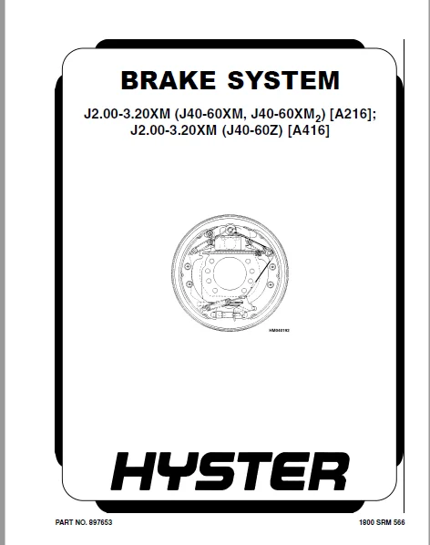
Brake System........................................................................................................................107
Safety Precautions Maintenance and Repair...........................................................................................108
General.............................................................................................................................111
Description and Operation...........................................................................................................111
Service Brakes..................................................................................................................111
Master Cylinder.................................................................................................................111
Parking Brake...................................................................................................................112
Service Brake Repairs...............................................................................................................113
Remove and Disassemble..........................................................................................................113
Clean...........................................................................................................................114
Inspect.........................................................................................................................114
Assemble and Install............................................................................................................116
Adjust..........................................................................................................................119
Parking Brake Repair................................................................................................................121
Remove and Disassemble..........................................................................................................121
Assemble and Install............................................................................................................121
Adjust..........................................................................................................................121
Master Cylinder Repair..............................................................................................................123
Remove..........................................................................................................................123
Clean and Inspect...............................................................................................................124
Repair..........................................................................................................................124
Install.........................................................................................................................126
Service Brakes Adjustment...........................................................................................................127
Brake Pedal Adjustment..............................................................................................................127
Master Cylinder Adjustment..........................................................................................................127
Brake System Air Removal............................................................................................................127
Parking Brake Not Applied Switch Test...............................................................................................128
Torque Specifications...............................................................................................................128
Troubleshooting.....................................................................................................................128
1900SRM559-897639-(05-2004)-EN..............................................................................................................135
toc.....................................................................................................................................135
Hydraulic System....................................................................................................................135
Safety Precautions Maintenance and Repair...........................................................................................136
General.............................................................................................................................139
Description.........................................................................................................................139
Hydraulic System................................................................................................................139
Operation...........................................................................................................................143
Hydraulic System................................................................................................................143
Hydraulic Gear Pump.............................................................................................................143
Rotator Actuator Valve..........................................................................................................143
Steering Pump...................................................................................................................147
Hydraulic Tank Repair...............................................................................................................154
E1.50-3.20XM (E25-65XM, E25-65XM 2 ) (D114, F108), E1.50-2.00XM ................................................................154
J2.00-3.20XM (J40-60XM, J40-60XM 2 ) (A216) and J2.00-3.20XM (J4................................................................155
Inspect.........................................................................................................................156
Small Leaks, Repair.............................................................................................................156
Large Leaks, Repair.............................................................................................................156
Clean...........................................................................................................................156
Steam Method................................................................................................................156
Chemical Solution Method....................................................................................................157
Additional Methods for Tank Repair..............................................................................................157
E1.50-3.20XM (E25-65XM, E25-65XM 2 ), (D114, F108), E1.50-2.00XM................................................................157
J2.00-3.20XM (J40-60XM, J40-60XM 2 ) (A216) and J2.00-3.20XM (J4................................................................158
Filter Replacement..................................................................................................................158
Hydraulic Pump Repair...............................................................................................................159
E1.50-3.20XM (E25-65XM, E25-65XM 2 ) (D114, F108), N30XMH, and N................................................................159
J2.00-3.20XM (J40-60XM, J40-60XM 2 ) (A216), J2.00-3.20XM (J40-6................................................................160
Pump Seal, Replace and Pump Assemble............................................................................................161
Assemble Pump on Motor..........................................................................................................161
E1.50-3.20XM (E25-65XM, E25-65XM 2 ) (D114, F108), N30XMH, and N................................................................164
J2.00-3.20XM (J40-60XM, J40-60XM 2 ) (A216), J2.00-3.20XM (J40-6................................................................165
Main Control Valve Repair...........................................................................................................166
Steering Pump Repair................................................................................................................166
E1.50-3.20XM (E25-65XM, E25-65XM 2 ) (D114, F108), N30XMH, and N................................................................166
J2.00-3.20XM (J40-60XM, J40-60XM 2 ) (A216), J2.00-3.20XM (J40-6................................................................167
Pump, Assemble and Install......................................................................................................168
Rotary Actuator Valve Repair........................................................................................................170
Disassemble, Clean, and Inspect.................................................................................................170
Assemble........................................................................................................................170
Steering Control Unit Repair........................................................................................................171
Remove..........................................................................................................................171
Install.........................................................................................................................171
Steering Cylinder Repair............................................................................................................177
Main Control Valve Check and Adjust.................................................................................................177
Steering Relief Valve Check and Adjust..............................................................................................177
Specifications......................................................................................................................178
Relief Valve Pressures*.........................................................................................................178
Hydraulic Tank Capacity (dipstick full mark)....................................................................................178
Hydraulic Pump Capacities.......................................................................................................178
Troubleshooting.....................................................................................................................179
Steering........................................................................................................................179
Steering Housing and Steering Control Unit......................................................................................180
Hydraulic System................................................................................................................181
2000SRM562-897642(05-2004)-EN...............................................................................................................187
toc.....................................................................................................................................187
Main Control Valve..................................................................................................................187
Safety Precautions Maintenance and Repair...........................................................................................188
General.............................................................................................................................191
Description.........................................................................................................................191
Operation...........................................................................................................................192
E1.50-3.20XM (E25-65XM, E25-65XM 2 ) [D114, F108], E1.50-2.00XM ................................................................194
J2.00-3.20XM (J40-60XM, J40-60XM 2 ) [A216], and J2.00-3.20XM (J................................................................194
Lift Section....................................................................................................................194
Tilt Section....................................................................................................................194
Tilt Backward...............................................................................................................194
Tilt Forward................................................................................................................195
Relief Valve....................................................................................................................196
Main Control Valve Repair...........................................................................................................197
Remove..........................................................................................................................197
Disassemble.....................................................................................................................197
Clean and Inspect...............................................................................................................197
Assemble........................................................................................................................201
Install [E1.50-3.20XM (E25-65XM, E25-65XM 2 ) (D114, F108), E1.5................................................................201
Install [J2.00-3.20XM (J40-65XM, J40-60XM 2 ) (A216) and J2.00-3................................................................202
Control Lever Linkage Repair........................................................................................................202
Remove [E1.50-3.20XM (E25-65XM, E25-65XM 2 ) (D114, F108), E1.50................................................................202
Disassemble [E1.50-3.20XM (E25-65XM, E25-65XM 2 ) (D114, F108), ................................................................202
Assemble and Install [E1.50-3.20XM (E25-65XM, E25-65XM 2 ) (D114................................................................202
Control Valve Linkage Repair........................................................................................................204
Remove and Disassemble [E1.50-3.20XM (E25-65XM, E25-65XM 2 ) (D1................................................................204
Assemble and Install [E1.50-3.20XM (E25-65XM, E25-65XM 2 ) (D114................................................................204
Control Lever Linkage Repair........................................................................................................205
Remove [J2.00-3.20XM (J40-60XM, J40-60XM 2 ) (A216) and J2.00-3.................................................................205
Disassemble [J2.00-3.20XM (J40-60XM, J40-60XM 2 ) (A216) and J2.................................................................205
Assemble and Install [J2.00-3.20XM (J40-60XM, J40-60XM 2 ) (A216................................................................207
Pressure Relief Valve Check and Adjustment..........................................................................................208
Primary Relief Valve............................................................................................................208
Secondary Relief Valve..........................................................................................................208
Troubleshooting.....................................................................................................................209
2100SRM103-910102(11-2004)-UK-EN............................................................................................................215
toc.....................................................................................................................................215
Tilt Cylinders......................................................................................................................215
Safety Precautions Maintenance and Repair...........................................................................................216
General.............................................................................................................................219
Description.........................................................................................................................219
Tilt Cylinder Repair................................................................................................................219
Remove..........................................................................................................................219
Disassemble.....................................................................................................................219
Clean...........................................................................................................................219
Assemble........................................................................................................................220
Tilt Cylinders With O-Ring or Single-Lip Seals..............................................................................220
Tilt Cylinders for XM and XMS Models........................................................................................221
Tilt Cylinders for H700-800A and Early Model H700-920B......................................................................222
Install.........................................................................................................................223
Tilt Cylinders Using Chevron Packing........................................................................................223
Install.................................................................................................................225
Tilt Cylinder Leak Check............................................................................................................227
Tilt Cylinder Stroke and Mast Tilt Angle Adjustment.................................................................................228
Torque Specifications...............................................................................................................229
Piston Rod Nut..................................................................................................................229
Retainer........................................................................................................................230
Troubleshooting.....................................................................................................................231
tables..................................................................................................................................215
Table 1. Movement Rates (Maximum) for Tilt Cylinders................................................................................228
2200SRM289-897071(08-1985)-EN...............................................................................................................235
INTRODUCTION............................................................................................................................235
General.............................................................................................................................235
Lift Truck Control..................................................................................................................235
PRINCIPLES OF OPERATION.................................................................................................................236
The Silicon Controlled Rectifier (SCR)..............................................................................................238
A Motor Circuit That Operates With Pulses...........................................................................................239
The SCR 1 "OFF" Circuit.............................................................................................................240
Induction Current From The Motor....................................................................................................244
The Logic Box.......................................................................................................................244
SCR Control (Hydraulic Pump)........................................................................................................249
Contactors..........................................................................................................................250
Circuit Protection..................................................................................................................251
Warning Indicators..................................................................................................................251
Sequence of Operation...............................................................................................................252
2200SRM560-897640(06-2004)-UK-EN............................................................................................................256
toc.....................................................................................................................................256
Electrical System...................................................................................................................256
Safety Precautions Maintenance and Repair...........................................................................................257
General.............................................................................................................................262
Description.........................................................................................................................263
ZX Series Display Panels........................................................................................................263
Display Panel...............................................................................................................263
Basic Display Panels........................................................................................................263
Early Display Panel.....................................................................................................263
Later Display Panel.....................................................................................................263
Performance Display.........................................................................................................265
Brush Wear Indicators.......................................................................................................269
SEM Display Panels - Features...................................................................................................269
Descriptions of Common Features.............................................................................................270
LED Symbol Indicators - SEM.............................................................................................270
LCD Screen..............................................................................................................270
Battery Discharge Indicator (BDI).......................................................................................270
Service Reminder........................................................................................................271
Status Codes............................................................................................................271
Hourmeter...............................................................................................................271
Additional Features of Premium Display Panel................................................................................271
Descriptions of Additional Features.........................................................................................271
LCD Screen..............................................................................................................271
Operator Passwords......................................................................................................271
Daily Checklist and Service Items.......................................................................................272
Performance Modes.......................................................................................................272
Status Code Lists.......................................................................................................272
Adjustment of BDI.......................................................................................................272
SEM Display Panel Indicators....................................................................................................272
All Indicator Symbols.......................................................................................................272
Hourmeter Indicator Symbol..................................................................................................273
Wrench Symbol...............................................................................................................273
Battery Symbol..............................................................................................................273
Battery Discharge Indicator (BDI)...........................................................................................273
Brake Fluid Too Low Symbol..................................................................................................273
Parking Brake Symbol........................................................................................................273
Fasten Seat Belt Symbol.....................................................................................................273
LCD Screen (Standard Display Panel).........................................................................................273
Additional Components of Premium Display Panel..................................................................................273
Alpha Numerical Screen......................................................................................................273
STAR Push Button............................................................................................................274
Push Buttons ##1 Through ##5 - SEM..........................................................................................274
Other Control Components........................................................................................................274
Display Panel Components Replacement................................................................................................275
ZX Panel Replacement............................................................................................................275
Display Panel Assembly..........................................................................................................275
Key Switch, Replace.............................................................................................................276
Indicator LEDs..................................................................................................................276
Battery Indicators..............................................................................................................276
Digital Display (Performance Display Panel Only)................................................................................276
Status Code or Performance Level Switches and Indicator LEDs (Pe................................................................276
Basic Display Panel, Replace Parts..............................................................................................276
Performance Display Panel, Replace Parts........................................................................................278
SEM Display Panel Replacement.......................................................................................................279
Motor Controller (SR or SP) Replacement.............................................................................................281
Remove..........................................................................................................................281
Install.........................................................................................................................281
Control Components Replacement......................................................................................................282
Start Switch, Replace...........................................................................................................282
Brake Light Switch, Replace.....................................................................................................282
Seat Switch, Replace............................................................................................................283
External Seat Switch, Adjust....................................................................................................284
Switch for Optional Seat Brake, Replace.........................................................................................284
Parking Brake Switch, Replace...................................................................................................285
Direction Switches (MONOTROL Pedal), Replace....................................................................................286
Direction Control Switches (Steering Column), Replace...........................................................................287
Direction Control Switches, E70-120XL 3 (Steering Column).......................................................................288
Brake Fluid Switch, Replace.....................................................................................................288
Brush Wear and Overtemperature Sensors..........................................................................................288
Rocker Switches for Lights......................................................................................................288
Accelerator Position Sensor, Replace............................................................................................289
On-Demand Steering Components...................................................................................................291
Lights, Converter, Relay, and Reverse Alarm.....................................................................................293
Incandescent Brake, Tail, and Reverse Light Assembly, Replace...............................................................293
LED Brake, Tail, and Reverse Light Assembly, Replace........................................................................293
Remove..................................................................................................................293
Install.................................................................................................................293
Flashing Light Assembly, Replace............................................................................................295
Front, Rear Driving Light, or Spot Light Assemblies, Replace................................................................295
Operator Compartment Light Assembly, Replace................................................................................297
Converter, Replace..........................................................................................................297
Relay, Replace..............................................................................................................298
Reverse Alarm, Replace......................................................................................................298
Horn and Horn Button............................................................................................................298
Horn Switch and Cover.......................................................................................................299
Hydraulic Pump Switches.........................................................................................................299
Control and Power Fuses Check.......................................................................................................299
ZX Motor Controllers............................................................................................................299
SEM Motor Controllers...........................................................................................................304
SEM Controller Field Diagnostic Procedure.......................................................................................304
Armature FET Test...........................................................................................................304
Field FET Test..............................................................................................................304
Brush Wear and Overtemperature Sensors Check - ZX Motor Controll....................................................................308
Thermal Sensors - SEM Motor Controllers Check.......................................................................................309
Start Switch Adjustment.............................................................................................................310
Accelerator Potentiometer and Start Switch, E70-120XL, E70-120XL................................................................311
E70-120XL...................................................................................................................311
E70-120XL 3.................................................................................................................311
Direction Switches (MONOTROL)...................................................................................................311
Brake Light Switch Adjustment.......................................................................................................313
Seat Switch Check...................................................................................................................314
Optional Seat Brake Switch Adjustment...............................................................................................314
Parking Brake Switch Adjustment.....................................................................................................315
Direction Switches Check............................................................................................................315
Monotrol Pedal..................................................................................................................315
Steering Column.................................................................................................................316
Hydraulic Pump Switch Adjustment....................................................................................................316
MONOTROL or Accelerator Pedal Adjustment............................................................................................316
Accelerator Position Sensor Adjustment..............................................................................................317
2200SRM581-897723(07-1997)-EN...............................................................................................................322
EV-T100E SCR MOTOR CONTROLLER, Description, Adjustments, Troubleshooting, Repairs And Theory............................................322
EV-T100E SCR MOTOR CONTROLLER, Description, Adjustments, Troubleshooting, Repairs, And Theory ......................................322
Model Number Data For EV-T100 Controller........................................................................................323
TABLE 1. Terminal And Plug Wire Connections For Control Card JH ....................................................................327
TABLE 2. Terminal And Plug Wire Connections For Hydraulic Pump Control Card LP......................................................328
TABLE 3. Terminal And Plug Wire Connections For Control Card JH.....................................................................329
TABLE 4. Terminal And Plug Wire Connections For Hydraulic Pump Control Card LP......................................................330
TABLE 5. Terminal And Plug Wire Connections For Control Card JH.....................................................................331
TABLE 6. Terminal And Plug Wire Connections For TMM1 Module.........................................................................332
TABLE 7. Terminal And Plug Wire Connections For Control Card JY.....................................................................333
REGISTER PARAMETERS.................................................................................................................334
General.........................................................................................................................334
Function Numbers................................................................................................................334
CONTROL CARD, CHECKS AND ADJUSTMENTS................................................................................................334
HAND SET............................................................................................................................335
How To Check And Adjust The Registers...........................................................................................335
How To Scroll Through The Fault Codes And Clear Them............................................................................335
Checks And Adjustments On The Work Bench........................................................................................336
When The Hand Set Is Connected To A Control Card Installed In A Lift Truck......................................................337
FUNCTION NUMBER DESCRIPTIONS........................................................................................................337
TRACTION CONTROL CARDS (LABEL LETTERS-JH AND JY)....................................................................................339
PUMP CONTROL CARD (LABEL LETTER LP).................................................................................................346
TROUBLESHOOTING.....................................................................................................................349
Status Codes....................................................................................................................350
REGISTER MAPS.......................................................................................................................350
TABLE 8. STATUS CODES LIST..........................................................................................................351
TABLE 9. REGISTER MAP FOR CONTROL CARDS ZH AND ZY (TRACTION)........................................................................352
TABLE 10. REGISTER MAP FOR CONTROL CARD ZP (HYDRAULIC PUMP).........................................................................352
STATUS CODE CHARTS......................................................................................................................360
REPAIRS.................................................................................................................................386
GENERAL.............................................................................................................................388
FUSES...............................................................................................................................389
THE POWER TRANSISTOR (TR1) ASSEMBLY.................................................................................................389
Thermal Protector (TP)..........................................................................................................389
Remove The TR1 Assembly.........................................................................................................389
How To Check The TR1 Assembly...................................................................................................390
Install The TR1 Assembly........................................................................................................390
Check Capacitor C1..............................................................................................................390
DIODES D3 AND D4....................................................................................................................391
Check The Diodes D3 And D4......................................................................................................391
Replacement, Diodes D3 And D4 ..................................................................................................391
SUPPRESSORS.........................................................................................................................391
MOTOR CURRENT SENSOR................................................................................................................391
CONTACTORS..........................................................................................................................392
Contactor Repair................................................................................................................392
CONTROL CARD........................................................................................................................392
CONTROL CARD PLUGS..................................................................................................................393
Brush Wear Indicators...........................................................................................................395
THEORY OF OPERATION (EV-T100 MOTOR CONTROLLER)..........................................................................................396
ELECTRONIC SPEED CONTROLS...........................................................................................................396
The Power Transistor "Switch"...................................................................................................396
A Motor Circuit That Operates With Pulses.......................................................................................397
Traction Circuit................................................................................................................398
Hydraulic Pump Motor............................................................................................................398
BASIC CIRCUIT OPERATION.............................................................................................................398
SRO Circuit (Traction Circuit Only).............................................................................................399
Pulse Monitor Trip (PMT) (Traction Circuit Only)................................................................................399
INDUCTION CURRENT FROM THE MOTOR....................................................................................................399
CONTROL CARDS.......................................................................................................................400
Control Card Adjustments (Traction Circuit).....................................................................................400
Accelerator Control.............................................................................................................404
TRANSITOR CONTROL (HYDRAULIC PUMP MOTOR)............................................................................................404
CONTACTORS..........................................................................................................................405
CIRCUIT PROTECTION..................................................................................................................405
Traction Circuit Fuses..............................................................................................................405
Current Limit.......................................................................................................................406
Thermal Protection..................................................................................................................406
Suppressors.........................................................................................................................406
TRUCK MANAGEMENT MODULE (TMM1)......................................................................................................406
2200SRM596-897825(11-1995)-EN...............................................................................................................409
EV-100 TRANSISTOR MOTOR CONTROLLER, Parameter Tables....................................................................................409
REGISTER PARAMETERS.................................................................................................................409
General.........................................................................................................................409
Function Numbers................................................................................................................409
CONTROL CARD, CHECKS AND ADJUSTMENTS................................................................................................409
REGISTER PARAMETERS.................................................................................................................410
TABLE 1. EV-T100 Parameters-E/J2.00-3.20XM (36 to 48 V).............................................................................411
TABLE 2. EV-T100 Parameters-E2.00-3.20XM (36 to 48V) ...............................................................................414
TABLE 3. EV-T100 Parameters-E/J2.00-3.20XM (36 to 48V)..............................................................................417
TABLE 4. EV-T100 Parameters-E2.00-3.20XM (72 to 80V)................................................................................420
TABLE 5. EV-T100 Parameters-All Lift Trucks (72 to 80 volts)........................................................................423
TABLE 6. EV-T100 Parameters-All Lift Trucks (36 to 80 volts) (Hydraulic Pump Card Type LP)..........................................426
TABLE 7. EV-T100 Parameters-All Lift Trucks (24 to 80 volts) (Hydraulic Pump Card Type HP)..........................................429
2200SRM597-897830(07-2001)-UK-EN............................................................................................................432
toc.....................................................................................................................................432
Troubleshooting and Adjustments with a Computer.....................................................................................432
Safety Precautions Maintenance and Repair...........................................................................................433
Computer System.....................................................................................................................436
Connect PC to Control Card......................................................................................................437
HYTECH™ Software Program............................................................................................................438
How to Start HYTECH Software Program............................................................................................438
Communications Port Selection...................................................................................................439
Controller and Lift Truck Verification..........................................................................................440
Lift Truck Series Selection.....................................................................................................441
Undefined Controller Card.......................................................................................................441
Controller Card Register Parameter List.........................................................................................442
How to Enter New Parameter......................................................................................................443
How to Save Changed Parameter File..............................................................................................444
How to Load Saved Parameter File................................................................................................444
How to Return to Factory Default Settings.......................................................................................445
How to Save Changes to Controller Card..........................................................................................446
How to View Status Codes........................................................................................................446
Saving Status Code to Disk......................................................................................................448
Closing and Clearing Status Code List...........................................................................................448
Communications Program (Modem)......................................................................................................449
Requirements....................................................................................................................449
README File.....................................................................................................................450
GE Sentry Software®.................................................................................................................451
Getting Started.................................................................................................................451
Where to Get Help...............................................................................................................451
Hardware and Software Requirements..............................................................................................451
GE SENTRY SOFTWARE Installation.................................................................................................451
How to Start GE SENTRY Program..................................................................................................452
How to Reset MIN and MAX Display................................................................................................453
How to Exit GE SENTRY Program...................................................................................................454
tables..................................................................................................................................432
Table 1. Cable Connections - Computer to Control....................................................................................436
Table 2. Adapter Pins (DB25F to DB9)................................................................................................436
Table 3. Plug-Z Connection..........................................................................................................438
Table 4. Cable Connections - Modem to Controller....................................................................................449
2200SRM724-1463733(04-2001)-EN..............................................................................................................458
TRANSISTOR MOTOR CONTROLLERS (SR AND SP) DESCRIPTION, CHECKS & ADJUSTMENTS, TROUBLESHOOTING, REPAIRS, AND THEORY OF OPERATION...........458
DESCRIPTION.........................................................................................................................458
General.........................................................................................................................458
Model Number Data For Transistor Motor Controllers (SR and SP)..................................................................459
MOTOR CONTROLLER, CHECKS AND ADJUSTMENTS............................................................................................461
CHECKS AND ADJUSTMENTS USING A HAND SET.............................................................................................462
General.........................................................................................................................462
Connect Hand Set................................................................................................................463
Start Sequence..................................................................................................................463
Check Or Delete Stored Status Codes.............................................................................................463
Returning The Lift Truck To Normal Operation....................................................................................464
Checks And Adjustments On The Work Bench........................................................................................464
How To Check And Adjust The Registers...........................................................................................466
ADJUSTMENTS - FUNCTION PARAMETERS...................................................................................................467
General.........................................................................................................................467
Function Numbers................................................................................................................467
When The Hand Set Is Connected To A Motor Controller In The Lift Truck..........................................................468
FUNCTION NUMBER DESCRIPTIONS........................................................................................................469
TRACTOR MOTOR CONTROLLER (LABEL LETTER - SR)........................................................................................469
FUNCTIONS WITH PREMIUM DISPLAY PANEL ONLY...........................................................................................474
PUMP MOTOR CONTROLLER (LABEL LETTER - SP)...........................................................................................476
FUNCTIONS WITH PREMIUM DISPLAY PANEL ONLY...........................................................................................479
TROUBLESHOOTING - STATUS CODE CHARTS................................................................................................484
TROUBLESHOOTING.................................................................................................................485
General.....................................................................................................................485
Status Codes................................................................................................................485
REPAIRS.............................................................................................................................514
GENERAL.........................................................................................................................514
GENERAL MAINTENANCE INSTRUCTIONS................................................................................................514
Special Precautions.........................................................................................................514
FUSES...........................................................................................................................517
CONTACTORS......................................................................................................................517
Contactor Repair............................................................................................................517
CONTACTOR DRIVER MODULE.........................................................................................................519
Replace Contactor Driver....................................................................................................519
MOTOR CONTROLLER PLUG...........................................................................................................519
BRUSH WEAR INDICATORS...........................................................................................................519
THERMAL SENSORS.................................................................................................................520
REPLACE MOTOR CONTROLLER........................................................................................................520
THEORY OF OPERATION.................................................................................................................526
GENERAL.........................................................................................................................526
DESCRIPTION OF SEM SYSTEM.......................................................................................................526
OPERATION OF SEM SYSTEM (SR MOTOR CONTROLLER)...................................................................................527
Reverse Circuit.............................................................................................................527
Performance and Efficiency..................................................................................................527
Field Weakening.............................................................................................................528
Regenerative Braking........................................................................................................528
INTRODUCTION....................................................................................................................528
General.....................................................................................................................528
Creep Speed.................................................................................................................528
Controlled Acceleration.....................................................................................................528
Current Limit...............................................................................................................529
BRAKING.........................................................................................................................529
Regenerative Braking to Zero Speed..........................................................................................529
Pedal Position Braking......................................................................................................529
Auto Braking................................................................................................................529
AUXILIARY SPEED CONTROL.........................................................................................................529
Field Weakening.............................................................................................................529
Speed Limits................................................................................................................530
RAMP OPERATION..................................................................................................................530
Ramp Start..................................................................................................................530
Anti-Rollback...............................................................................................................530
STEER PUMP CONTACTOR TIME DELAY.................................................................................................530
COIL DRIVERS AND INTERNAL COIL SUPPRESSION......................................................................................530
SYSTEM PROTECTIVE OVERRIDE......................................................................................................530
SRO (Static Return to Off)..................................................................................................530
Accelerator Volts Hold Off..................................................................................................530
Pulse Monitor Trip (PMT)....................................................................................................530
Thermal Protector (TP)......................................................................................................531
Low Voltage.................................................................................................................531
SP PUMP MOTOR CONTROLLERS.......................................................................................................531
CONTACTOR DRIVER MODULE.........................................................................................................531
DIAGNOSTICS.....................................................................................................................532
System Diagnostics..........................................................................................................532
Standard Status Codes.......................................................................................................532
Stored Status Codes.........................................................................................................532
Hourmeter Readings..........................................................................................................532
Maintenance Management Capability...........................................................................................532
TABLE 8 - LARGE (P) PLUG (23 PIN) CONNECTIONS/DESCRIPTIONS FOR MOTOR CONTROLLERS................................................533
TABLE 9 - SMALL PLUG (12 PIN) CONNECTIONS/DESCRIPTIONS FOR MOTOR CONTROLLERS....................................................534
2200SRM725-1463739(03-1999)-EN..............................................................................................................538
SEM DISPLAY PANEL.......................................................................................................................540
GENERAL.............................................................................................................................540
SEM DISPLAY PANEL FEATURES..........................................................................................................540
Description Of Common Features..................................................................................................540
LED SYMBOL INDICATORS...........................................................................................................540
LCD SCREEN......................................................................................................................540
BATTERY DISCHARGE INDICATOR (BDI)...............................................................................................540
SERVICE REMINDER................................................................................................................541
STATUS CODES....................................................................................................................541
HOURMETER.......................................................................................................................541
Additional Features Of Premium Display Panel....................................................................................541
Descriptions Of Additional Features (Available With The Premium Display)........................................................541
LCD SCREEN......................................................................................................................541
OPERATOR PASSWORDS..............................................................................................................541
DAILY CHECK LIST AND SERVICE ITEMS..............................................................................................542
PERFORMANCE MODES...............................................................................................................542
STATUS CODE LISTS...............................................................................................................542
ADJUSTMENT OF BDI...............................................................................................................543
SEM DISPLAY PANEL INDICATORS........................................................................................................543
All Indicator Symbols...........................................................................................................543
Hourmeter Indicator Symbol......................................................................................................544
Wrench Indicator Symbol.........................................................................................................544
Battery Indicator Symbol........................................................................................................544
Battery State-Of-Charge (BDI)...................................................................................................544
Brake Fluid Too Low Symbol......................................................................................................544
Parking Brake Symbol............................................................................................................544
Fasten Seat Belt Symbol.........................................................................................................544
LCD Screen (Standard Display Panel).............................................................................................544
ADDITIONAL COMPONENTS OF THE PREMIUM DISPLAY PANEL..................................................................................544
Alpha Numeric screen............................................................................................................544
"Star" Push Button .............................................................................................................545
Push Buttons #1 Through #5......................................................................................................545
ADJUSTMENTS WITH A COMPUTER.............................................................................................................546
COMPUTER SYSTEM.....................................................................................................................546
Connect A PC To the SEM Display Panel...........................................................................................546
ITW SWITCHES SOFTWARE PROGRAM (For SEM Display Panel)...............................................................................547
Description.....................................................................................................................547
Where To Get Help...............................................................................................................547
Hardware and Software Requirements..............................................................................................547
How to Start The ITW SWITCHES Program...........................................................................................548
Menus...........................................................................................................................548
Create A Setup File.............................................................................................................556
REPLACEMENT.............................................................................................................................576
GENERAL.............................................................................................................................576
SEM DISPLAY PANEL...................................................................................................................576
Removal And Replacement.........................................................................................................576
2200SRM739-1463745(09-1999)-EN..............................................................................................................578
SR (SEM) AND SP TRANSISTOR MOTOR CONTROLLER, Parameter Tables...........................................................................578
GENERAL.............................................................................................................................578
Function Numbers................................................................................................................578
MOTOR CONTROLLER CHECKS AND ADJUSTMENTS.............................................................................................579
Parameter Tables................................................................................................................579
TABLE 1. SR (SEM) Register Parameters For Traction Motor Controller - E1.50-2.500XM (D114)(48V) Standard Speed Motor And Cushion....580
TABLE 2. SR (SEM) Register Parameters For Traction Motor Controller - E1.50-2.50XM (D114)(48V) Standard Speed Motor And PSS Tire....582
TABLE 3. SP Register Parameters For Pump Motor Controller - E1.50-2.50XM (D114)(48V)................................................584
TABLE 4. SR (SEM) Register Parameters For Traction Motor Controller - E2.50-3.20XM (F108)*72 to 80V)(9 Inch Traction Motor).........586
TABLE 5. SR (SEM) Register Parameters For Traction Motor Controller - E2.50-3.20XM (F108)(72 to 80V)(11 Inch Traction Motor)........588
TABLE 6. SP Register Parameters For Pump Motor Controller - E2.50-3.20XM (F108)(72 to 80V)..........................................590
TABLE 7. SR (SEM) Register Parameters For Traction Motor Controller - J2.50-3.20XM (A216)(72 to 80V)................................592
TABLE 8. SP Register Parameters For Pump Motor Controller - J2.50-3.20XM (A216)(72 to 80V)..........................................594
2200SRM942-1494238(06-2002)-EN..............................................................................................................597
toc.....................................................................................................................................597
Display Panel for SEM Controls......................................................................................................597
Safety Precautions Maintenance and Repair...........................................................................................598
General.............................................................................................................................601
SEM Display Panel Features..........................................................................................................601
Descriptions of Common Features.................................................................................................601
LED Symbol Indicators.......................................................................................................601
LCD Screen..................................................................................................................601
Battery Discharge Indicator (BDI)...........................................................................................601
Service Reminder............................................................................................................602
Status Codes................................................................................................................602
Hourmeter...................................................................................................................602
Additional Features of Premium Display Panel....................................................................................602
Descriptions of Additional Features (Available with Premium Disp................................................................602
LCD Screen..................................................................................................................602
Operator Passwords..........................................................................................................602
Daily Check List and Service Items..........................................................................................603
Performance Modes...........................................................................................................603
Status Code Lists...........................................................................................................603
Adjustment of BDI...........................................................................................................603
SEM Display Panel Indicators........................................................................................................603
All Indicator Symbols...........................................................................................................603
Hourmeter Indicator Symbol......................................................................................................604
Wrench Indicator Symbol.........................................................................................................604
Battery Indicator Symbol........................................................................................................604
Battery State-of-Charge (BDI)...................................................................................................604
Brake Fluid Too Low Symbol......................................................................................................604
Parking Brake Symbol............................................................................................................604
Fasten Seat Belt Symbol.........................................................................................................605
LCD Screen (Standard Display Panel).............................................................................................605
Additional Components of Premium Display Panel......................................................................................606
Alphanumeric Screen.............................................................................................................606
STAR Push Button................................................................................................................606
Push Buttons 1 Through 5........................................................................................................606
Adjustments With a Computer.........................................................................................................606
Computer System.................................................................................................................606
Connect PC to SEM Display Panel.............................................................................................607
ITW Switches Windows Software Program (for SEM Display Panel)...................................................................607
Description.................................................................................................................607
Where to Get Help...........................................................................................................608
Hardware and Software Requirements..........................................................................................608
Install.....................................................................................................................608
How to Start ITW SWITCHES Program...........................................................................................608
Menus.......................................................................................................................612
Sample Sessions.............................................................................................................620
Replacement.........................................................................................................................643
SEM Display Panel...............................................................................................................643
Remove and Replace..........................................................................................................643
tables..................................................................................................................................597
Table 1. Adapter Pins (DB25F to DB9)................................................................................................606
2200SRM947-1494933(08-2003)-UK..............................................................................................................649
toc.....................................................................................................................................649
Troubleshooting and Adjustments With a Computer.....................................................................................649
Safety Precautions Maintenance and Repair...........................................................................................650
Computer System.....................................................................................................................653
Connect a PC to a Control Card..................................................................................................654
Installation....................................................................................................................655
HYTECH™ Windows Software Program....................................................................................................655
How to Start the Program........................................................................................................655
DEMO Mode.......................................................................................................................656
Selecting the Communications Port...............................................................................................658
Verification of Controller and Lift Truck.......................................................................................659
Select Lift Truck Series........................................................................................................661
Controller Card Register Parameter List.........................................................................................662
How to Change a Parameter.......................................................................................................663
How to Save a Changed Parameter File............................................................................................664
How to Load a Saved Parameter File..............................................................................................665
How to Show and Remove Saved Parameter Files....................................................................................666
How to Return to Factory Default Settings.......................................................................................667
How to Save Changes to Control Card.............................................................................................668
How to View Status Codes........................................................................................................669
Saving Status Codes.............................................................................................................670
How to Show and Remove Saved Status Code Files..................................................................................672
Closing and Clearing Status Code List...........................................................................................672
How to View Saved Register Data and Saved Status Data...........................................................................673
How to Save Register Data and Status Code Data In .RTF and .TXT ................................................................675
GE Sentry™ Software Program.........................................................................................................676
Installation....................................................................................................................676
Description.....................................................................................................................676
How to Start GE SENTRY Program..................................................................................................676
How to Reset MIN and MAX Display................................................................................................681
Graphing Mode...................................................................................................................682
How to Exit GE SENTRY Program...................................................................................................683
tables..................................................................................................................................649
Table 1. Cable Connections - Computer to Control....................................................................................653
Table 2. Adapter Pins (DB25F to DB9)................................................................................................653
Table 3. Plug-Z Connection..........................................................................................................654
2240SRM001-899648(11-2003)-EN...............................................................................................................687
toc.....................................................................................................................................687
Industrial Battery..................................................................................................................687
Safety Precautions Maintenance and Repair...........................................................................................688
General.............................................................................................................................691
Lead-Acid Batteries.................................................................................................................691
Specific Gravity....................................................................................................................692
Chemical Reaction in a Cell.........................................................................................................692
Electrical Terms....................................................................................................................693
Battery Selection...................................................................................................................694
Battery Voltage.....................................................................................................................695
Battery as a Counterweight..........................................................................................................695
Battery Ratings.....................................................................................................................695
Kilowatt-Hours..................................................................................................................695
Battery Maintenance.................................................................................................................696
Safety Procedures...............................................................................................................696
Maintenance Records.............................................................................................................696
New Battery.....................................................................................................................696
Cleaning Battery................................................................................................................697
Adding Water to Battery.........................................................................................................698
Hydrometer......................................................................................................................699
Battery Temperature.............................................................................................................699
Charging Battery................................................................................................................700
Types of Battery Charges....................................................................................................701
Methods of Charging.........................................................................................................702
Troubleshooting Charger.....................................................................................................703
Knowing When Battery Is Fully Charged.......................................................................................703
Where to Charge Batteries.......................................................................................................703
Equipment Needed............................................................................................................703
Battery Connectors..............................................................................................................704
Battery Care....................................................................................................................704
tables..................................................................................................................................687
Table 1. Battery Capacity Terms.....................................................................................................695
4000SRM521-897506(05-2004)-EN...............................................................................................................709
toc.....................................................................................................................................709
Mast................................................................................................................................709
Safety Precautions Maintenance and Repair...........................................................................................710
General.............................................................................................................................713
Description and Operation...........................................................................................................713
Carriages.......................................................................................................................713
Mast Mounts.....................................................................................................................715
Two-Stage Mast, Limited Free-Lift (LFL).............................................................................................717
Description and Operation.......................................................................................................717
Two-Stage Mast, Full Free-Lift (FFL)................................................................................................718
Description and Operation.......................................................................................................718
Three-Stage Mast, Full Free-Lift (FFL)..............................................................................................720
Description and Operation.......................................................................................................720
Cylinder Cushion During Lifting Sequence............................................................................................723
Cylinder Cushion During Lowering Sequence...........................................................................................724
4000SRM522-897507(05-2004)-EN...............................................................................................................727
toc.....................................................................................................................................727
Mast................................................................................................................................727
Safety Precautions Maintenance and Repair...........................................................................................728
General.............................................................................................................................731
Safety Procedures When Working Near Mast............................................................................................731
Forks Repair........................................................................................................................733
Remove..........................................................................................................................733
Install.........................................................................................................................734
Carriages Repair....................................................................................................................734
Standard Carriage, Remove.......................................................................................................734
Hang-On Sideshift Carriage, Remove..............................................................................................735
Standard Carriage and Hang-On Sideshift Carriage, Repair........................................................................736
Standard Carriage, Install......................................................................................................736
Hang-On Sideshift Carriage, Install.............................................................................................737
Integral Sideshift Carriage.....................................................................................................737
Remove......................................................................................................................737
Clean and Inspect...........................................................................................................739
Repair......................................................................................................................739
Install.....................................................................................................................740
Mast Repair.........................................................................................................................740
Remove..........................................................................................................................740
Two-Stage LFL and Two-Stage FFL Masts, Disassemble..............................................................................742
Three-Stage FFL Mast............................................................................................................749
Disassemble.................................................................................................................749
Mast and Chains, Clean and Inspect..........................................................................................752
Two-Stage LFL and Two-Stage FFL Mast, Assemble..................................................................................753
Three-Stage FFL Mast, Assemble..................................................................................................754
Install.........................................................................................................................756
Lift Cylinders Repair...............................................................................................................757
Main Lift Cylinders, Remove.....................................................................................................757
Free-Lift Cylinder, Remove......................................................................................................757
Lift Cylinders, Disassemble.....................................................................................................758
Lift Cylinders, Assemble........................................................................................................758
Main Lift Cylinders, Install....................................................................................................761
Free-Lift Cylinder, Install.....................................................................................................762
Header Hose Arrangements............................................................................................................762
Two-Stage LFL Mast, New Hose Install............................................................................................762
Two-Stage LFL Mast, Adjust Hoses After Installation.............................................................................768
Two-Stage FFL Mast, New Hose Install............................................................................................768
Two-Stage FFL Mast, Adjust Hoses After Installation.............................................................................773
Three-Stage FFL Mast, New Hose Install..........................................................................................775
Three-Stage FFL Mast, Adjust Hoses After Installation...........................................................................785
Header Hose Arrangement.............................................................................................................786
Two-Stage LFL Mast, New Hose Install............................................................................................786
Two-Stage LFL Mast, Adjust Hoses After Installation.............................................................................786
Two-Stage FFL Mast, New Hose Install............................................................................................790
Two-Stage FFL Mast, Adjust Hoses After Installation.............................................................................795
Three-Stage FFL Mast, New Hose Install..........................................................................................797
Three-Stage FFL Mast, Adjust Hoses After Install................................................................................802
Lift and Tilt System Leak Check.....................................................................................................806
Lift Cylinders Leak Check.......................................................................................................806
Tilt Cylinders Leak Check.......................................................................................................806
Tilt Cylinders Adjustment...........................................................................................................807
Lift Chains Adjustment..............................................................................................................808
Mast Adjustment.....................................................................................................................810
Carriage Adjustment.................................................................................................................812
Troubleshooting.....................................................................................................................812
tables..................................................................................................................................727
Table 1. Hook-Type Carriage Chain Adjustment........................................................................................809
Table 2. Pin-Type Carriage Chain Adjustment.........................................................................................809
8000SRM231-910442(03-2004)-EN...............................................................................................................817
toc.....................................................................................................................................817
Metric and Inch (SAE) Fasteners.....................................................................................................817
Safety Precautions Maintenance and Repair...........................................................................................818
General.............................................................................................................................821
Threaded Fasteners..............................................................................................................821
Nomenclature, Threads...........................................................................................................821
Strength Identification.........................................................................................................822
Cotter (Split) Pins.............................................................................................................822
Fastener Torque Tables..........................................................................................................827
Conversion Table................................................................................................................829
tables..................................................................................................................................817
Table 1. Bolts and Screws...........................................................................................................823
Table 2. Studs and Nuts.............................................................................................................824
Table 3. Torque Nuts................................................................................................................825
Table 4. Torque Nuts With Nylon Insert..............................................................................................826
Table 5. Torque Values for Metric Fasteners*........................................................................................827
Table 6. Torque Values for Inch Fasteners*..........................................................................................828
Table 7. Conversion Table for Metric and English Units..............................................................................829
Table 8. Cotter Pin Dimensional Data................................................................................................830
Table 9. Cotter Pin Dimensional Data................................................................................................831
Table 10. Cotter Pin Dimensional Data...............................................................................................832
Table 11. Cotter Pin Dimensional Data...............................................................................................834
8000SRM552-897903(05-1999)-EN...............................................................................................................837
8000SRM561-897641(05-1999)-EN...............................................................................................................893
COUNTERWEIGHTS..........................................................................................................................893
HYDRAULIC SYSTEM........................................................................................................................893
WHEELS AND TIRES........................................................................................................................894
BATTERY SPECIFICATIONS - E2.00-3.20XM (E45-65XM, E45-65XM2, N30XMH, N30XMH2)............................................................894
BATTERY SPECIFICATIONS - J2.00-3.20XM (J40-65XM, J40-65XM2).............................................................................895
CAPACITIES..............................................................................................................................895
E45-65XM MAST SPEEDS (36 or 48 Volt) Americas...........................................................................................896
E40-65XM, E40-65XM2, N30XMH2 MAST SPEEDS (36 or 48 Volt) (3/99) Americas................................................................899
E2.00-3.20XM MAST SPEEDS (72 or 80 Volt) Europe.........................................................................................901
E2.00-3.20XM, E2.00-3.20XM2, MAST SPEEDS (72 or 80 Volt) (3/99) Europe..................................................................906
J40-65XM MAST SPEEDS (36 or 48 Volt) Americas...........................................................................................909
J40-65XM, J40-65XM2, MAST SPEEDS (36 or 48 Volt) (3/99) Americas........................................................................912
J2.00-3.20XM MAST SPEEDS (72 or 80 Volt) Europe.........................................................................................914
TORQUE SPECIFICATIONS...................................................................................................................922
REFERENCE TABLE.........................................................................................................................925
Adhesives And Sealants..............................................................................................................925
8000SRM589-897781(09-1996)-EN...............................................................................................................927
FIGURE 1. J2.00-3.200XM TRANSISTOR CONTROLLERS FOR TRACTION MOTOR AND HYDRAULIC PUMP MOTORS.............................................927
FIGURE 2. E1.50-3.20XMS TRANSISTOR CONTROLLERS FOR TRACTION MOTOR AND HYDRAULIC PUMP MOTORS.............................................928
FIGURE 3. SCHEMATIC DIAGRAM, TRANSISTOR CONTROLLERS FOR TRACTION MOTOR AND HYDRAULIC PUMP MOTORS........................................931
FIGURE 4. WIRING DIAGRAM, J2.00-3.20XM TRANSISTOR CONTROLLERS FOR TRACTION MOTOR AND HYDRAULIC PUMP MOTORS..............................933
FIGURE 5. WIRING DIAGRAM, J2.00-3.20XM TRANSISTOR CONTROLLER FOR TRACTION MOTOR, CONTACTOR CONTROLLER FOR HYDRAULIC PUMP................935
FIGURE 6. WIRING DIAGRAM, E1.50-3.20XMS TRANSISTOR CONTROLLERS FOR TRACTION MOTOR AND HYDRAULIC PUMP MOTORS.............................937
FIGURE 7. WIRING DIAGRAM, E1.50-3.20XMS TRANSISTOR CONTROLLER FOR TRACTION MOTOR, CONTACTOR CONTROL FOR HYDRAULIC PUMP..................939
FIGURE 8. WIRE HARNESS, J2.00-3.20XM....................................................................................................941
FIGURE 9. POWER CABLES AND BATTERY CONNECTOR, J2.00-3.20XM..............................................................................942
FIGURE 10. E1.50-3.20XM TRUCK WIRING....................................................................................................943
FIGURE 11. TRUCK POWER CABLES...........................................................................................................944
FIGURE 12. TRUCK POWER CABLES...........................................................................................................945
FIGURE 13. HYDRAULIC LINKAGE SWITCH AND CHASSIS WIRING DETAILS..........................................................................946
FIGURE 14. WIRING SCHEMATIC FOR THE INSTRUMENT PANEL, E/J2.00-3.20XM....................................................................947
FIGURE 15. DISPLAY PANELS AND PLUG CONNECTIONS..........................................................................................948
FIGURE 16. CONFIGURATION OF THE EV-T100 MOTOR CONTROLLER MODULE.........................................................................949
FIGURE 17. CONTROL CARD CONNECTIONS.....................................................................................................949
FIGURE 18. TRUCK MANAGEMENT MODULE (TMM1)...............................................................................................953
FIGURE 19. WIRING SCHEMATIC, E2.00-3.20XM TRANSISTOR CONTROLLERS FOR TRACTION MOTOR AND HYDRAULIC PUMP MOTORS...........................955
FIGURE 20. DETAIL OF BATTERY CONNECTOR WITH +12 VOLT TAP................................................................................956
FIGURE 21. HYDRAULIC SCHEMATIC, E/J2.00-3.20XM E1.50-2.00XMS............................................................................957
FIGURE 22. WIRING DIAGRAM FOR LIGHTS....................................................................................................959
8000SRM742-1464329(06-2004)-UK-EN...........................................................................................................960
toc.....................................................................................................................................960
Electrical Diagrams.................................................................................................................960
Safety Precautions Maintenance and Repair...........................................................................................961
HYSTER A216 (J2.00-3.20XM) SERVICE MANUAL – PDF DOWNLOAD:
IMAGES PREVIEW OF THE MANUAL:
PLEASE NOTE:
- This is not a physical manual but a digital manual – meaning no physical copy will be couriered to you. The manual can be yours in the next 2 mins as once you make the payment, you will be directed to the download page IMMEDIATELY.
- This is the same manual used by the dealers inorder to diagnose your vehicle of its faults.
- Require some other service manual or have any queries: please WRITE to us at [email protected]
S.V