Hyster A257 A262 (B80ZAC) Service Manual – PDF DOWNLOAD
Original price was: $98.95.$29.95Current price is: $29.95.
Hyster A257 A262 (B80ZAC) Service Manual – PDF DOWNLOAD
Description
Hyster A257 A262 (B80ZAC) Service Manual – PDF DOWNLOAD
DESCRIPTION:
Hyster A257 A262 (B80ZAC) Service Manual – PDF DOWNLOAD
HOW TO FIND THE DESIRED PART NUMBER
WHEN THE PART NUMBER AND THE NEXT
HIGHER ASSEMBLY IS NOT KNOWN:
1 ·. Determine the function and application of the part
required. Turn to the Sections Page. Choose the
general area of reference most likely to include the
part.
2. Turn to the section you chose. Use the Section
Table of Contents to determine the assembly
which would normally contain the part required.
Then locate the part on the assembly breakdown
page.
WHEN THE PART NUMBER IS NOT KNOWN
AND THE NEXT HIGHER ASSEMBLY IS
KNOWN:
3. Determine tl”le c1~semblyJher-eq1..1ired part is used
on. Turn to the Table of Contents (Page i).
4. Locate the assembly the required part is used on
and turn to the page indicated for that assembly.
Then locate the part on the assembly breakdown
page.
WHEN THE PART NUMBER IS KNOWN:
5. Use the Numerical Index (Page 8-1) to find the
part number. Turn to the page listed and locate the
part as indicated by the item number.
GENERAL:
The assembly breakdowns include part numbers,
descriptions, quantities required, keys and
footnotes to help in selecting. correct parts.
6. Parts Supersessiori Information. Part numbers that
have this history will be displayed in the parts list
in the order that they were superseded (from oldest
to newest). The superseded part numbers will be
shown with a line through them.
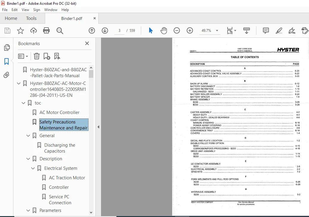
TABLE OF CONTENTS:
Hyster A257 A262 (B80ZAC) Service Manual – PDF DOWNLOAD
Hyster-B60ZAC-and-B80ZAC-Pallet-Jack-Parts-Manual................................................  1
Hyster-B80ZAC-AC-Motor-Controller1640805-2200SRM1286-(04-2011)-US-EN.............................189
	toc..........................................................................................189
		AC Motor Controller......................................................................189
		Safety Precautions Maintenance and Repair................................................190
		General..................................................................................193
			Discharging the Capacitors...........................................................193
		Description..............................................................................194
			Electrical System....................................................................194
				AC Traction Motor................................................................195
				Controller.......................................................................195
				Service PC Connection............................................................195
		Parameters...............................................................................195
			General..............................................................................195
		Parameter Description....................................................................197
			Parameters...........................................................................197
				Extended Shift...................................................................197
				Walk Speed (Both Directions).....................................................197
				Hi Speed (FWD)...................................................................197
				Hi Speed (REV)...................................................................197
				Minimum Acceleration.............................................................197
				Maximum Acceleration.............................................................197
				Plugging.........................................................................197
				ADS-Neutral......................................................................197
				ADS-Throttle.....................................................................197
				Pick Acceleration................................................................197
				Pick Deceleration................................................................198
				Battery Full Voltage.............................................................198
				Lift Interrupt...................................................................198
		Troubleshooting..........................................................................198
			General..............................................................................198
			Non-Status Code Errors...............................................................199
				Powered Black Screen.............................................................199
				Tiller Oscillation and Bias (EPAS Option)........................................200
			Status Codes.........................................................................200
		Electrical Checks........................................................................293
			General Electrical System Checks.....................................................293
			Static Checks on Power and Ground Connections........................................293
			Static Checks on CAN Connections.....................................................294
			Tiller Harness Shorts and Continuity Checks..........................................295
		Control Card Functional Test.............................................................296
		Dash Display.............................................................................299
			General..............................................................................299
			Startup..............................................................................299
			Status LED...........................................................................299
			Performance Mode Indicator...........................................................299
			Hourmeter............................................................................300
			Battery Charge Indicator.............................................................300
			Fault Log............................................................................300
		Connector Pin-Outs.......................................................................301
		System Logic Diagram.....................................................................302
	tables.......................................................................................189
		Table 1. Parameter Default Values........................................................196
		Table 2. Fault Codes.....................................................................201
Hyster-B80ZAC-AC-Motor-Repair-1640802-0620SRM1283-(04-2011)-US-EN................................305
	toc..........................................................................................305
		AC Motor Repair..........................................................................305
		Safety Precautions Maintenance and Repair................................................306
		General..................................................................................309
			Accessing the Drive Unit Compartment.................................................309
				B60-80Z AC and B60-80Z HD........................................................309
				C60-80Z AC and T5-7Z AC..........................................................310
		Special Precautions......................................................................311
			Discharging the Capacitors...........................................................311
		Description..............................................................................312
		AC Motor Repair..........................................................................312
			Remove...............................................................................312
			Disassemble..........................................................................312
			Inspect..............................................................................314
			Assemble.............................................................................314
			Install..............................................................................314
		Troubleshooting..........................................................................315
Hyster-B80ZAC-Diagrams-1640808-8000SRM1288-(04-2011)-US-EN.......................................319
	toc..........................................................................................319
		Diagrams.................................................................................319
		Safety Precautions Maintenance and Repair................................................320
Hyster-B80ZAC-Frame-4025071-0100SRM1448-(04-2011)-US-EN..........................................333
	toc..........................................................................................333
		Frame....................................................................................333
		Safety Precautions Maintenance and Repair................................................334
		General..................................................................................337
		Frame Separation and Assembly............................................................338
			Disassemble..........................................................................338
			Assemble.............................................................................338
		Painting Instructions....................................................................339
		Label Replacement........................................................................339
Hyster-B80ZAC-Lifting-Mechanism-4025073-4000SRM1452-(07-2011)-US-EN..............................343
	toc..........................................................................................343
		Lifting Mechanism........................................................................343
		Safety Precautions Maintenance and Repair................................................344
		General..................................................................................347
		Description of Operation.................................................................347
		Load Wheel...............................................................................347
			Remove...............................................................................347
			Install..............................................................................348
		Casters..................................................................................349
			Caster Adjustment Check..............................................................349
			Caster Adjust Heavy-Duty.............................................................349
			Caster Replacement...................................................................350
			Disassemble..........................................................................350
				Heavy-Duty.......................................................................350
			Assemble.............................................................................351
				Heavy-Duty.......................................................................351
		Rear Link and Load Wheel.................................................................351
			Remove...............................................................................351
			Install..............................................................................353
		Pull Rod.................................................................................355
			Remove...............................................................................355
			End Replacement......................................................................355
			Install..............................................................................355
			Fork Height Adjustment...............................................................356
		Rocker Arm...............................................................................358
			Remove...............................................................................358
			Install..............................................................................359
		Upper Link...............................................................................359
			Remove...............................................................................359
			Install..............................................................................360
		Troubleshooting..........................................................................361
Hyster-B80ZAC-Parts-Manual-4025069-[A257-A262]-H-PM-US-EN-(03-2012)..............................365
	FRAME/DRIVE UNIT.............................................................................377
		COVERS...................................................................................380
		DECAL AND PLATE LOCATION.................................................................382
		DRIVE UNIT ASSEMBLY A257.................................................................384
		DRIVE UNIT ASSEMBLY A262.................................................................386
		POWER STEER MOTOR AND GEARS OPTION A257..................................................388
		POWER STEER MOTOR AND GEARS OPTION A262..................................................390
		MASTER DRIVE UNIT A257 - MANUAL STEERING ................................................392
		MASTER DRIVE UNIT A257 - POWER ASSIST STEERING ..........................................396
		MASTER DRIVE UNIT A262 - MANUAL STEERING ................................................400
		MASTER DRIVE UNIT A262 - POWER ASSIST STEERING ..........................................404
		TRACTION MOTOR A257......................................................................408
		TRACTION MOTOR A262......................................................................410
		SHIELD...................................................................................412
		BATTERY RETENTION........................................................................414
		BATTERY RETENTION GALVANIZED.............................................................415
		BATTERY DISCONNECT.......................................................................416
	ELECTRICAL SYSTEM............................................................................419
		ELECTRICAL ASSEMBLY......................................................................422
		CONTROLLER ENCLOSURE.....................................................................424
		EE CONTACTOR ASSEMBLY A257...............................................................426
		WIRE HARNESS THERMOSTAT..................................................................428
		WIRE HARNESS MAIN........................................................................430
		WIRE HARNESS HANDRAIL....................................................................433
		WIRE HARNESS STANDARD SWIVEL TILLER......................................................434
		WIRE HARNESS QUICK PICK..................................................................435
		WIRE HARNESS TILLER......................................................................436
		WIRE HARNESS SWIVEL TILLER - COAST CONTROL, FREEZER .....................................437
		CONTROL MODULE TILLER INTERFACE..........................................................439
	STEER HANDLE/BRAKE SYSTEM....................................................................441
		TILLER WELDMENT ARM ASSEMBLY MANUAL OR POWER ASSIST STEERING - WITH COMPOSITE HEAD ......444
		TILLER HANDLE ARM ASSEMBLY COMPOSITE - POWER ASSIST STEERING ............................446
		TILLER HEAD ASSEMBLY COMPOSITE...........................................................448
		TILLER WELDMENT ARM ASSEMBLY MANUAL OR POWER ASSIST STEERING - METAL HANDLE AND HEAD ....450
		TILLER HEAD ASSEMBLY RUGGEDIZED METAL....................................................452
		TILLER SWIVEL ASSEMBLY MANUAL STEERING...................................................456
		TILLER SWIVEL ASSEMBLY POWER ASSIST STEERING.............................................458
		AUXILIARY CONTROL BOX....................................................................462
		BRAKE ASSEMBLY A262......................................................................464
		BRAKE ASSEMBLY A257......................................................................465
	LIFT LINKAGE AND FORKS.......................................................................467
		LIFT LINKAGE.............................................................................470
		CASTER SPRING LOADED.....................................................................474
		CASTER ASSEMBLY HEAVY DUTY...............................................................476
		SINGLE LOAD WHEEL TWO BEARING............................................................478
		SINGLE LOAD WHEEL FOUR BEARING...........................................................479
		SINGLE LOAD WHEEL TWO BEARING SEALED.....................................................480
		SINGLE LOAD WHEEL FOUR BEARING SEALED....................................................481
		DUAL LOAD WHEEL STANDARD.................................................................482
		DUAL LOAD WHEEL SEALED BEARINGS..........................................................483
	HYDRAULIC SYSTEM.............................................................................485
		HYDRAULIC ASSEMBLY.......................................................................488
		HYDRAULIC POWER UNIT.....................................................................490
		LIFT CYLINDER ASSEMBLY...................................................................492
	OPTIONS......................................................................................493
		RF TERMINAL..............................................................................496
		STROBE LIGHT POLE MOUNTED................................................................498
		BACK-UP ALARM............................................................................500
		CONVENIENCE TRAY.........................................................................502
		COAST CONTROL MANUAL STEERING............................................................504
		COAST CONTROL POWER ASSIST STEERING......................................................506
		ADVANCED COAST CONTROL...................................................................508
		ADVANCED COAST CONTROL VALVE ASSEMBLY....................................................510
		BATTERY ROLLER ASSEMBLY..................................................................512
		LOAD BACKREST............................................................................514
		LOAD BACKREST BOLT-ON....................................................................516
		FORK WELDMENTS AND PULL ROD OPTIONS A257.................................................518
		FORK WELDMENTS AND PULL ROD OPTIONS A262.................................................522
	NUMERICAL INDEX..............................................................................525
Hyster-B80ZAC-Report-an-Error....................................................................537
Hyster-B80ZAC-User-Interface-1654668-2200SRM1323-(04-2011)-US-EN.................................538
	toc..........................................................................................538
		User Interface...........................................................................538
		Safety Precautions Maintenance and Repair................................................539
		General..................................................................................542
			Description..........................................................................542
			Dash Display Menu Access (Standard Handle)...........................................542
			Dash Display Menu Access (Metal Handle Option).......................................543
		Menu Navigation..........................................................................544
			Standard Handle......................................................................544
			Metal Handle Option..................................................................546
		Dash Display Versions....................................................................547
		Supervisor Menu..........................................................................548
			View Versions........................................................................549
			Hourmeters...........................................................................549
			Diagnostics..........................................................................549
				Fault Log........................................................................550
				Controller Inputs................................................................551
				Control Handle Inputs............................................................551
				Run Diagnostics..................................................................552
					Traction Motor...............................................................553
					Pump Motor and Valve.........................................................553
					Control Handle...............................................................553
					Temperatures.................................................................554
					Power Steering...............................................................554
			Service Reminder.....................................................................554
			Change Supervisor Password...........................................................555
			Operator Modes.......................................................................556
			Exit to Run Mode.....................................................................556
	tables.......................................................................................538
		Table 1. Corresponding Buttons...........................................................546
		Table 2. Supervisor Menu.................................................................548
		Table 3. Diagnostics Menu................................................................550
		Table 4. Controller Inputs...............................................................551
		Table 5. Control Handle Inputs...........................................................551
		Table 6. Run Diagnostics Menu............................................................552
HYSTER A257 A262 (B80ZAC) SERVICE MANUAL – PDF DOWNLOAD:
IMAGES PREVIEW OF THE MANUAL:
PLEASE NOTE:
- This is the SAME manual used by the dealers to troubleshoot any faults in your vehicle. This can be yours in 2 minutes after the payment is made.
- Contact us at [email protected] should you have any queries before your purchase or that you need any other service / repair / parts operators manual.
S.V