Trusted Business
Verified & Licensed
Virus Free Files
100% Safe Downloads
Secure Payment
SSL Protected
Instant Delivery
Available Immediately
Sale!
Hyster B114 (E20-25B, E30BS) Service Manual – PDF DOWNLOAD
Original price was: $98.95.$30.95Current price is: $30.95.
Hyster B114 (E20-25B, E30BS) Service Manual – PDF DOWNLOAD
Instant PDF Download
Available immediately
Save to Your Device
Download & keep forever
Antivirus Scanned
100% virus-free
Trusted Worldwide
175,000+ customers
Description
Hyster B114 (E20-25B, E30BS) Service Manual – PDF DOWNLOAD
FILE DETAILS:
Hyster B114 (E20-25B, E30BS) Service Manual – PDF DOWNLOAD
Language : English
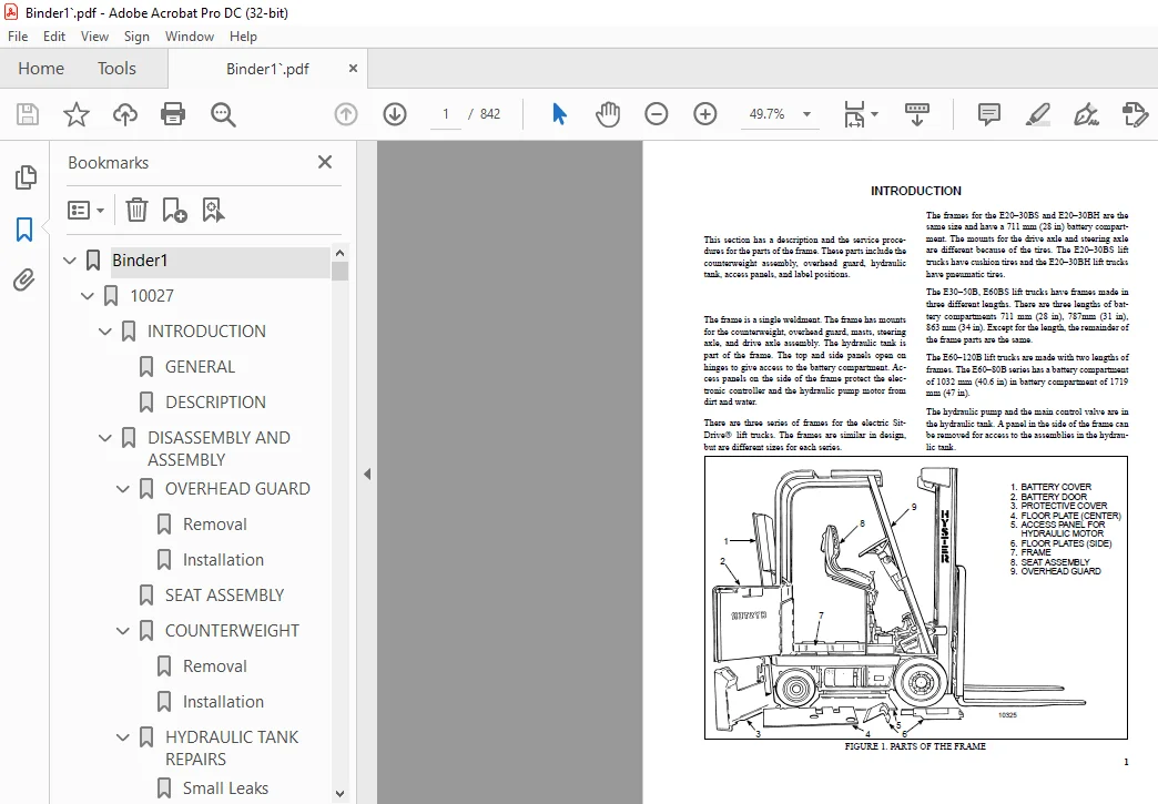
Pages : 842
Downloadable : Yes
File Type : PDF
Size: 23.3 MB
TABLE OF CONTENTS:
Hyster B114 (E20-25B, E30BS) Service Manual – PDF DOWNLOAD
Binder1..........................................................................................................  1
	10027........................................................................................................  1
		INTRODUCTION.............................................................................................  1
			GENERAL..............................................................................................  1
			DESCRIPTION..........................................................................................  1
		DISASSEMBLY AND ASSEMBLY.................................................................................  2
			OVERHEAD GUARD.......................................................................................  2
				Removal..........................................................................................  2
				Installation.....................................................................................  2
			SEAT ASSEMBLY........................................................................................  2
			COUNTERWEIGHT........................................................................................  2
				Removal..........................................................................................  3
				Installation.....................................................................................  3
			HYDRAULIC TANK REPAIRS...............................................................................  3
				Small Leaks......................................................................................  3
				Large Leaks......................................................................................  4
				Steam Method Of Cleaning.........................................................................  4
				Chemical Solution Method of Cleaning.............................................................  4
				Other Methods....................................................................................  4
			LABEL REPLACEMENT....................................................................................  5
	22401........................................................................................................  7
		INTRODUCTION.............................................................................................  7
			GENERAL..............................................................................................  7
			LEAD-ACID BATTERIES..................................................................................  7
			SPECIFIC GRAVITY.....................................................................................  7
			THE CHEMICAL REACTION IN A CELL......................................................................  8
		ELECTRICAL TERMS.........................................................................................  9
			HOW TO SELECT THE BATTERY............................................................................  9
			VOLTAGE OF A BATTERY.................................................................................  9
			THE BATTERY AS A COUNTERWEIGHT....................................................................... 10
			BATTERY RATINGS...................................................................................... 10
				Kilowatt-Hours................................................................................... 11
		BATTERY MAINTENANCE...................................................................................... 11
			SAFETY PROCEDURES.................................................................................... 11
			MAINTENACE RECORDS................................................................................... 12
			THE NEW BATTERY...................................................................................... 12
			HOW TO CLEAN THE BATTERY............................................................................. 13
			HOW TO ADD WATER..................................................................................... 13
			THE HYDROMETER....................................................................................... 14
			BATTERY TEMPERATURE.................................................................................. 14
			CHARGING THE BATTERY................................................................................. 15
				Types Of Battery Charges......................................................................... 16
				Methods Of Charging.............................................................................. 17
				Troubleshooting The Charger...................................................................... 17
				How To Know When The Battery Is Fully Charged.................................................... 18
			WHERE TO CHARGE THE BATTERIES........................................................................ 18
				Equipment Needed................................................................................. 18
			BATTERY CONNECTORS................................................................................... 19
			BATTERY CARE......................................................................................... 19
	130062....................................................................................................... 21
		INTRODUCTION............................................................................................. 21
			General.............................................................................................. 21
			Description.......................................................................................... 21
		REPAIRS.................................................................................................. 22
			Removal Of The Speed Reducer And Differential........................................................ 22
			Disassembly.......................................................................................... 23
			Assembly............................................................................................. 24
			Installation Of The Drive Assembly................................................................... 28
		TROUBLESHOOTING.......................................................................................... 28
	160054....................................................................................................... 30
		INTRODUCTION............................................................................................. 30
			GENERAL.............................................................................................. 30
			DESCRIPTION.......................................................................................... 30
			OPERATION............................................................................................ 30
		REPAIRS.................................................................................................. 30
			STEERING WHEEL AND COLUMN ASSEMBLY................................................................... 30
			TYPE "A" STEERING COLUMN ASSEMBLY.................................................................... 32
				Removal And Disassembly.......................................................................... 32
				Assembly And Installation........................................................................ 32
			TYPE "A" STEERING COLUMN............................................................................. 33
			TYPE "A" STEERING COLUMN............................................................................. 34
			TYPE "B" STEERING COLUMN............................................................................. 35
				Removal And Disassembly.......................................................................... 35
				Assembly And Installation........................................................................ 35
			TYPE "B" STEERING COLUMN............................................................................. 36
				Disassembly of Steering Control Unit............................................................. 37
				Cleaning of Steering Control Unit................................................................ 37
				Assembly of Steering Control Unit................................................................ 39
		CHECKS AND ADJUSTMENTS................................................................................... 42
			REMOVE AIR FROM THE SYSTEM........................................................................... 42
		TROUBLESHOOTING.......................................................................................... 43
	180013....................................................................................................... 44
		INTRODUCTION............................................................................................. 44
			GENERAL.............................................................................................. 44
			DESCRIPTION.......................................................................................... 44
		REPAIRS.................................................................................................. 44
			REMOVAL AND DISASSEMBLY.............................................................................. 44
			CLEANING ............................................................................................ 45
			ASSEMBLY............................................................................................. 45
		CHECKS AND ADJUSTMENTS................................................................................... 45
			CHECKS............................................................................................... 45
	190097....................................................................................................... 46
		INTRODUCTION............................................................................................. 46
			DESCRIPTION.......................................................................................... 46
			OPERATION............................................................................................ 46
				Flow Control Valve............................................................................... 48
				Relief Valve..................................................................................... 48
		REPAIRS.................................................................................................. 49
			REMOVAL.............................................................................................. 49
			DISASSEMBLY.......................................................................................... 49
			CLEANING............................................................................................. 51
			INSPECTION........................................................................................... 51
			ASSEMBLY............................................................................................. 52
			INSTALLATION......................................................................................... 53
		CHECKS AND ADUSTMENTS.................................................................................... 54
			CHECK THE OUTPUT OF THE PUMP......................................................................... 54
			CHECK FOR AIR IN THE HYDRAULIC SYSTEM................................................................ 54
		TROUBLESHOOTING.......................................................................................... 56
	190098....................................................................................................... 59
		INTRODUCTION............................................................................................. 59
			GENERAL.............................................................................................. 59
			DESCRIPTION.......................................................................................... 59
			OPERATION............................................................................................ 59
				Pump............................................................................................. 59
				Relief Valve..................................................................................... 60
		REPAIRS.................................................................................................. 61
			REMOVAL.............................................................................................. 61
			DISASSEMBLY.......................................................................................... 61
			ASSEMBLY............................................................................................. 62
			INSTALLATION......................................................................................... 63
		CHECKS AND ADJUSTMENTS................................................................................... 63
			CHECKING THE RELIEF PRESSURE OF THE RELIEF VALVE..................................................... 63
				Lift Trucks With Internal Combustion Engines..................................................... 63
				Electric Lift Trucks............................................................................. 63
				Electric Lift Trucks With Adjustable Relief Valve................................................ 64
		SPECIFICATIONS........................................................................................... 65
		TROUBLESHOOTING.......................................................................................... 65
	620145....................................................................................................... 66
		......................................................................................................... 66
		......................................................................................................... 67
		......................................................................................................... 68
		......................................................................................................... 69
		......................................................................................................... 70
		......................................................................................................... 71
		......................................................................................................... 72
		......................................................................................................... 73
		......................................................................................................... 74
		......................................................................................................... 75
		......................................................................................................... 76
		......................................................................................................... 77
		......................................................................................................... 78
		......................................................................................................... 79
		......................................................................................................... 80
		......................................................................................................... 81
		......................................................................................................... 82
		......................................................................................................... 83
		......................................................................................................... 84
		......................................................................................................... 85
		......................................................................................................... 86
		......................................................................................................... 87
		......................................................................................................... 88
		......................................................................................................... 89
		......................................................................................................... 90
		......................................................................................................... 91
		......................................................................................................... 92
		......................................................................................................... 93
		......................................................................................................... 94
		......................................................................................................... 95
	620294....................................................................................................... 96
		toc...................................................................................................... 96
			DC Motor Maintenance................................................................................. 96
			Safety Precautions Maintenance and Repair............................................................ 97
			General..............................................................................................100
			Brush and Commutator Inspection......................................................................100
				Hydraulic Pump Motor and Traction Motor..........................................................100
				Steering Pump Motor..............................................................................103
				Normal Commutator Surface........................................................................103
				Commutator Problems..............................................................................103
			Brush Replacement....................................................................................107
			Stoning the Commutator...............................................................................109
			Motors Repair........................................................................................111
				Disassemble......................................................................................111
					Traction Motor and Hydraulic Pump Motor......................................................111
					Steering Pump Motor..........................................................................115
				Assemble.........................................................................................115
					Traction Motor and Hydraulic Pump Motor......................................................115
					Steering Pump Motor..........................................................................116
			Brush Alignment, Traction and Hydraulic Motors.......................................................119
			Tests for Damaged Field and Armature.................................................................119
				Test for an Open Circuit in Armature.............................................................119
				Test for Short Circuit in One Armature Winding...................................................120
				Test for Short Circuit to Armature Shaft.........................................................120
				Test for Open Circuit in Field Coil..............................................................120
				Test for Short Circuit in Field Coil.............................................................120
				Test for Short Circuit between Field and Motor Case..............................................121
				Brush Holder Test................................................................................121
			Troubleshooting......................................................................................121
		tables................................................................................................... 96
			Table 1. Normal Commutator Surfaces..................................................................102
			Table 2. Commutator Problems.........................................................................103
			Table 3. Brush Wear Replacement Guide................................................................107
	1400209......................................................................................................126
		INTRODUCTION.............................................................................................126
			General..............................................................................................126
			Description..........................................................................................126
		REPAIRS..................................................................................................126
			Removal Of The Drive Axle (E20-30BS).................................................................126
			Installation.........................................................................................128
			Removal Of The Drive Axle (E20-30BH).................................................................128
			Installation.........................................................................................129
			Wheels And Tires.....................................................................................130
			Removal Of The Speed Reducer And Differential........................................................131
			Disassembly..........................................................................................134
			Assembly.............................................................................................135
			Installation Of The Drive Assembly...................................................................137
		TROUBLESHOOTING..........................................................................................139
	1600212......................................................................................................140
		MANUAL STEERING SYSTEM (E20-30BS)........................................................................140
			System Description...................................................................................141
			Steering Wheel Assembly..............................................................................141
			Steering Column Assembly.............................................................................142
			Steering Gear Assembly...............................................................................144
			Tie Rods And Drag Link...............................................................................150
			Steering Axle Assembly...............................................................................151
			Wheel Hubs And Spindles..............................................................................156
		POWER STEERING SYSTEM....................................................................................159
			System Description...................................................................................159
			Steering Wheel And Column Assembly...................................................................160
			Steering Control Unit................................................................................162
			Power Steering Motor And Pump........................................................................162
			Power Steering Axle Assembly.........................................................................163
			Steering Cylinder....................................................................................164
			Wheel Hubs And Spindles..............................................................................168
			Inspection Requirements..............................................................................168
			Manual Steering Checks And Adjustments...............................................................173
		E20-30BH STEERING SYSTEM SUPPLEMENT......................................................................175
		MANUAL STEERING SYSTEM...................................................................................175
			Steering Axle Assembly...............................................................................175
			Wheel Hubs And Spindles..............................................................................178
			Steer Wheel And Tire.................................................................................180
		POWER STEERING SYSTEM....................................................................................181
			Power Steering Assembly..............................................................................181
			Steering Cylinder....................................................................................182
			Wheel Hubs And Spindles..............................................................................183
			Checks And Adjustments...............................................................................184
	1800205......................................................................................................186
		INTRODUCTION.............................................................................................186
			General..............................................................................................186
			Description..........................................................................................186
		REPAIRS..................................................................................................187
			Parking Brake Assembly...............................................................................187
		ADJUSTMENTS..............................................................................................188
			Adjustment of the Hand Brake Linkage.................................................................188
			Adjustment of the Linkage for the Hand and Seat Brake................................................188
	1800210......................................................................................................189
		INTRODUCTION.............................................................................................189
			General..............................................................................................189
			Description And Operation............................................................................189
		REPAIRS..................................................................................................189
			Removal And Disassembly..............................................................................189
		CHECKS AND ADJUSTMENTS...................................................................................192
			Checks...............................................................................................192
			Adjustments..........................................................................................192
		TROUBLESHOOTING..........................................................................................193
	1900161......................................................................................................194
		INTRODUCTION.............................................................................................194
			General..............................................................................................194
			Description..........................................................................................194
			The Control Valve....................................................................................196
		REPAIRS..................................................................................................201
			Hydraulic Pump.......................................................................................201
			Main Control Valve...................................................................................203
			Hydraulic Pump Contactor.............................................................................208
			Contactor Repair.....................................................................................208
		CHECKS AND ADJUSTMENTS...................................................................................209
			Adjusting The Pressure Relief Valve..................................................................209
			Adjustment Of The Control Linkage....................................................................209
			Hydraulic Pump Switch................................................................................209
		TROUBLESHOOTING..........................................................................................210
	2100103......................................................................................................212
		General..................................................................................................214
		Description..............................................................................................214
		Tilt Cylinder............................................................................................214
			Remove...............................................................................................214
			Disassemble..........................................................................................214
			Clean................................................................................................214
			Assemble.............................................................................................214
				Tilt Cylinders with O-Ring or Single-Lip Seals...................................................214
				Tilt Cylinders for XM and XMS Models.............................................................216
				Tilt Cylinders for H700-800A and Early Model H700-920B...........................................217
			Install..............................................................................................218
				Tilt Cylinders Using Chevron Packing.............................................................219
					Install......................................................................................220
		Tilt Cylinder Leak Check.................................................................................222
		Tilt Cylinder Stroke and Mast Tilt Angle Adjustment......................................................223
		Torque Specifications....................................................................................223
			Piston Rod Nut.......................................................................................223
			Retainer.............................................................................................225
		Troubleshooting..........................................................................................226
	2200143......................................................................................................229
		INTRODUCTION.............................................................................................229
			GENERAL..............................................................................................229
		DESCRIPTION..............................................................................................229
			GENERAL..............................................................................................229
			STEERING COLUMN GAUGES, METERS AND INDICATORS........................................................232
			LED DISPLAY PANEL....................................................................................232
				Battery Discharge Indicators.....................................................................232
				Brush Wear Indicators............................................................................233
				Motor Temperature Indicators.....................................................................234
			"LX" SERIES DISPLAY PANEL............................................................................235
				Hourmeter Functions..............................................................................236
				Battery Indicator Function.......................................................................236
				Status Code Function.............................................................................236
			"ZX" SERIES DISPLAY PANELS...........................................................................236
				Display Panel....................................................................................237
				Basic Display Panels.............................................................................237
				Performance Display..............................................................................239
				Brush Wear Indicators............................................................................242
		CHECKS AND ADJUSTMENTS...................................................................................242
			GENERAL..............................................................................................242
		REPLACEMENT..............................................................................................243
			GENERAL..............................................................................................243
			METER REPLACEMENT....................................................................................243
			SENDER REPLACEMENT...................................................................................244
				Fuel Level Sender................................................................................244
				Pressure And Temperature Sender..................................................................244
			I.T.W. DISPLAY PANEL.................................................................................245
				Removal..........................................................................................245
			DISPLAY PANELS FOR THE EV - 100/200ZX MOTOR CONTROLLERS, COLUMN MOUNT................................246
				Removal..........................................................................................246
				Replacing Display Panel Assembly.................................................................246
				Indicator LEDs...................................................................................246
				Battery Indicators...............................................................................246
				Digital Display (Performance Disply Panel Only)..................................................246
				Status Code Or Performance Level Switches And Indicator LEDs (Performance Display Panel Only)....246
				Replacing Parts Of The Basic Display Panel.......................................................247
				Replacing Parts Of The Performance Display Panel.................................................249
			DISPLAY PANELS FOR THE EV-100/200ZX MOTOR CONTROLLERS, DASH MOUNT....................................249
				Removal And Replacement..........................................................................249
		SPECIFICATIONS...........................................................................................250
		TROUBLESHOOTING..........................................................................................251
	2200144......................................................................................................252
		ELECTRICAL WARNING DEVICES...............................................................................252
			GENERAL..............................................................................................252
			DESCRIPTION..........................................................................................252
				Operator Controlled Horns........................................................................252
				System Warning Lights, Buzzers and Bells.........................................................252
				Reverse Warning Horns............................................................................253
				Warning Lights...................................................................................253
			REPLACEMENT..........................................................................................254
				General..........................................................................................254
				Replacing Horns or Bells.........................................................................254
				Replacing Horn Relay or Buzzer...................................................................254
				Replacing Warning Lights.........................................................................254
				Light Assemblies.................................................................................255
				Replacing Flashing Units.........................................................................255
	2200464......................................................................................................256
		.........................................................................................................256
		.........................................................................................................257
		.........................................................................................................258
		.........................................................................................................259
		.........................................................................................................260
		.........................................................................................................261
		.........................................................................................................262
		.........................................................................................................263
		.........................................................................................................264
		.........................................................................................................265
		.........................................................................................................266
		.........................................................................................................267
		.........................................................................................................268
		.........................................................................................................269
		.........................................................................................................270
		.........................................................................................................271
		.........................................................................................................272
		.........................................................................................................273
		.........................................................................................................274
		.........................................................................................................275
		.........................................................................................................276
		.........................................................................................................277
		.........................................................................................................278
		.........................................................................................................279
		.........................................................................................................280
		.........................................................................................................281
		.........................................................................................................282
		.........................................................................................................283
		.........................................................................................................284
		.........................................................................................................285
		.........................................................................................................286
		.........................................................................................................287
		.........................................................................................................288
		.........................................................................................................289
		.........................................................................................................290
		.........................................................................................................291
	2260138......................................................................................................292
		INTRODUCTION.............................................................................................294
			GENERAL..............................................................................................294
			INDICATORS WITH METER MOVEMENT.......................................................................295
			BATTERY INDICATORS WITH LCD OR LED DISPLAYS..........................................................296
				Liquid Crystal Displays..........................................................................296
				Description, Sem Display Panel...................................................................299
				Light Emitting Diode Displays....................................................................300
				Description LX Series............................................................................300
				Description, ZX Series Display Panels............................................................301
		CHECKS AND ADJUSTMENTS...................................................................................302
			BATTERY INDICATORS WITHOUT LIFT INTERRUPT, EARLY MODELS..............................................302
			BATTERY INDICATORS WITH LIFT INTERRUPT, EARLY MODELS.................................................302
				Reset Potentiometer..............................................................................303
				Specific Gravity Alarm...........................................................................303
			BATTERY INDICATORS WITHOUT LIFT INTERRUPT, LATER MODELS..............................................304
			BATTERY INDICATORS WITH LIFT INTERRUPT, LATER MODELS.................................................304
				Reset Potentiometer..............................................................................304
				Discharge Potentiometer..........................................................................305
			LED DISPLAY WITH LIFT INTERRUPT......................................................................305
			CHECKING CURTIS 933-1 METER..........................................................................305
				Reset Check......................................................................................306
				Discharge Check..................................................................................306
				Lockout Check....................................................................................307
				LED's Do Not Illuminate..........................................................................307
				Hour Glass Icon..................................................................................307
			ADJUSTMENT OF CURTIS 933-1 METER.....................................................................307
			ADJUSTMENT OF SEVCON POWERGAUGE......................................................................308
		CURTIS DASH DISPLAY ASSEMBLY.............................................................................308
			Description/Features.................................................................................308
			Operation............................................................................................309
			Testing..............................................................................................309
				Inoperative Dash Display Assembly................................................................309
				Inoperative drive Mode Selection.................................................................309
				Troubleshooting With a Programmer Hand Set.......................................................310
				Troubleshooting Without a Programmer Hand Set....................................................310
				No Warnings Or Faults Displayed..................................................................311
				MIB/Dash Display Communication...................................................................312
				Lift Interrupt...................................................................................312
				Lost MIB Signal Displayed........................................................................313
				Lift Pump Hourmeter Input........................................................................313
				Forward/Reverse Hourmeter Inputs.................................................................313
				Removal..........................................................................................313
				Installation.....................................................................................314
				Adjustment (Set-up)..............................................................................314
		REPAIRS..................................................................................................315
			BATTERY INDICATORS...................................................................................315
				Replacement......................................................................................315
			CONTROLLER FOR THE BATTERY INDICATOR.................................................................315
				Replacement......................................................................................315
			DISPLAY PANEL COMPONENTS.............................................................................315
			REPLACING SEM DISPLAY PANEL..........................................................................316
			SEM DISPLAY PANEL REMOVAL............................................................................316
				Removal And Replacement..........................................................................316
	4000135......................................................................................................320
		Safety Procedures When Working Near Mast.................................................................322
		General..................................................................................................327
		Description..............................................................................................327
			Lowering Control Valve...............................................................................327
			Cylinders (General)..................................................................................330
			Cylinders (H520-620B, H700-800A).....................................................................330
				Retainer, Install................................................................................330
			Cylinders (H360-460B)................................................................................332
			Cylinders (Two-Speed)................................................................................335
		Lift Cylinder Repair.....................................................................................336
			Lift Cylinder Removal Without Removing Mast..........................................................336
				Standard Masts With Main Lift Cylinders Fastened to Crossmember of Inner Mast....................336
				Standard and Full Free-Lift Masts With Lift Cylinder Fastened to Crosshead.......................337
				Masts That Have Two Cylinders, Main Lift Cylinder and Free-Lift Cylinder.........................338
			Disasemble...........................................................................................338
			Assemble.............................................................................................338
			Lift Cylinder Installation in Mast...................................................................340
				Standard Masts With Main Lift Cylinder Fastened to Crossmember of Inner Mast.....................340
				Standard and Full Free-Lift Masts With Lift Cylinder Fastened to Crosshead.......................340
			Chevron-Style Packing................................................................................340
				Chevron-Style Packing Installation on Piston.....................................................341
				Chevron-Style Packing Installation in Packing Gland..............................................343
		Lift Cylinders for Vista Masts...........................................................................344
			Description..........................................................................................344
				Lowering Control Valve...........................................................................344
			Remove...............................................................................................346
			Disassemble..........................................................................................347
			Assemble.............................................................................................348
			Install..............................................................................................349
				Main Lift Cylinders..............................................................................349
				Free-Lift Cylinder...............................................................................349
		Lift System Leak Check...................................................................................349
		Specifications...........................................................................................350
		Troubleshooting..........................................................................................351
	4000167......................................................................................................354
		INTRODUCTION.............................................................................................354
			GENERAL..............................................................................................354
			STANDARD MASTS (Mast Assemblies Having Less Than Full Free-Lift.)....................................356
			FULL FREE-LIFT MASTS.................................................................................356
			THREE-STAGE MASTS....................................................................................358
			FOUR-STAGE MASTS.....................................................................................359
			SEQUENCE VALVE.......................................................................................359
	4000211......................................................................................................361
		INTRODUCTION.............................................................................................361
		REPAIRS..................................................................................................361
			Forks................................................................................................361
			Carriage.............................................................................................361
			Uprights.............................................................................................363
		CHECKS AND ADJUSTMENTS...................................................................................368
			Checking For Leaks In The Lift System................................................................368
			Adjusting The Tilt Cylinder Stroke And Backward Tilt Angle...........................................369
			Upright Adjustments..................................................................................370
		TROUBLESHOOTING..........................................................................................374
	8000213......................................................................................................375
		INTRODUCTION.............................................................................................375
			General..............................................................................................375
			Moving A Disabled Lift Truck.........................................................................375
		MAINTENANCE SCHEDULE.....................................................................................375
		MAINTENANCE PROCEDURES...................................................................................377
			Every 8 Hours or Daily...............................................................................377
				Hydraulic System.................................................................................377
				Battery..........................................................................................378
				Tires............................................................................................378
				Lift Mechanism...................................................................................378
				Forks............................................................................................378
				Lift Chain.......................................................................................379
				Upright..........................................................................................379
				Carriage.........................................................................................380
				Load Backrest Extension..........................................................................380
				Brakes...........................................................................................380
				Guages and Horn..................................................................................381
			Every 350 Hours or Two Months........................................................................381
				Brake Fluid......................................................................................381
				Hydraulic Tank Breather..........................................................................382
				Differential and Speed Reducer...................................................................382
				Uprights.........................................................................................382
				Forks............................................................................................382
				Electrical Inspection............................................................................384
			Every 2000 Hours or Yearly...........................................................................386
				Hydraulic System.................................................................................386
				Wheel Bearings...................................................................................386
				Brake Shoes......................................................................................386
			WHEELS AND TIRES.....................................................................................387
			CHANGING THE BATTERY.................................................................................389
	8000214......................................................................................................390
	8000215......................................................................................................393
		ELECTRICAL SYSTEM CABLING DIAGRAM........................................................................393
		ELECTRICAL SYSTEM SCHEMATIC DIAGRAM 36/48 VOLT (EARLY)...................................................394
		ELECTRICAL SYSTEM WIRING DIAGRAM 36/48 VOLT (EARLY)......................................................396
		ELECTRICAL SYSTEM SCHEMATIC DIAGRAM 36/48 VOLT (LATER)...................................................398
		ELECTRICAL SYSTEM WIRING DIAGRAM 36/48 VOLT (LATER)......................................................400
		HYDRAULIC SYSTEM SCHEMATIC...............................................................................402
	EV-1 info....................................................................................................403
		INTRODUCTION.............................................................................................403
			GENERAL..............................................................................................403
		PRINCIPLES OF OPERATION..................................................................................403
			LIFT TRUCK CONTROL...................................................................................403
			ELECTRONIC SPEED CONTROLS............................................................................404
				The Silicon Controlled Rectifier (SCR)...........................................................404
				The Traction Circuit That Operates With Pulses...................................................404
				The SCR 1 OFF Circuit............................................................................408
			THE CONTROL CARD FOR THE TRACTION CIRCUIT............................................................408
				SRO Circuit......................................................................................409
				Pulse Monitor Trip (PMT).........................................................................409
				Control Card Adjustments.........................................................................410
				C/L (Current Limit)..............................................................................410
				Plug.............................................................................................410
				Creep............................................................................................411
				C/A (Controlled Acceleration)....................................................................411
			THERMAL PROTECTION...................................................................................411
			THE 1A CIRCUIT.......................................................................................411
			FIELD WEAKENING......................................................................................412
			RAMP START...........................................................................................413
			ACCELERATOR CONTROL..................................................................................413
			CONTACTORS AND ELECTRONIC DRIVERS....................................................................413
				The Electronic Drivers...........................................................................413
				Contactors.......................................................................................413
			CIRCUIT PROTECTION...................................................................................415
				Current Limit....................................................................................415
				Thermal Protection...............................................................................415
				Traction Circuit Fuse............................................................................415
			SEQUENCE OF OPERATION................................................................................415
	EV-1.........................................................................................................426
		INTRODUCTION.............................................................................................426
			GENERAL..............................................................................................426
		SRO CIRCUIT AND PMT CIRCUIT..............................................................................427
			STATIC RETURN TO OFF(SRO) CIRCUIT....................................................................427
			PULSE MONITOR TRIP (PMT).............................................................................427
			THE SEQUENCE OF OPERATION............................................................................428
		TROUBLESHOOTING..........................................................................................428
			GENERAL PROCEDURES...................................................................................428
				FAULT IN THE CONTROL CIRCUIT.....................................................................431
		CHECKS AND REPAIRS.......................................................................................446
			GENERAL..............................................................................................446
			CHECK FOR THE CORRECT OPERATION......................................................................446
			CONTROL AND POWER FUSES..............................................................................447
			CONTROL CARD.........................................................................................447
				Removal..........................................................................................449
				Installation.....................................................................................449
			SCRs.................................................................................................449
				An SCR "QUICK REF"...............................................................................449
				Checking An SCR..................................................................................449
				The SCR 1 Assembly...............................................................................451
				Thermal Sensor...................................................................................451
				Checking SCR 1...................................................................................451
				Replacing The SCR 1 Assembly.....................................................................451
			THE INDUCTOR AND CAPACITOR ASSEMBLY (THE "OFF" CIRCUIT FOR SCR 1)....................................452
				Checking The Transformer and Inductor Assembly...................................................452
				Checking the Supressors for the SCR 2 and SCR 5..................................................452
				Checking the SCR 2 and SCR 5.....................................................................453
				Replacing the SCR 2 and SCR 5....................................................................453
				Checking The Capacitor C1........................................................................453
				D3 And D4 Heat Sink Assembly.....................................................................453
				Checking The Diodes D3 and D4....................................................................453
				Replacing The Diodes D3 and D4...................................................................454
			MOTOR CURRENT SENSOR.................................................................................454
			THE ELECTRONIC DRIVER MODULE.........................................................................454
			CONTACTORS...........................................................................................455
				"FORWARD" And "REVERSE" Contactors...............................................................455
			CONTACTOR REPAIR.....................................................................................456
				Remove A Contactor Assembly......................................................................456
				Contactor Contacts...............................................................................456
				Coil.............................................................................................456
			CHECK THE PMT CIRCUIT................................................................................457
	Fastner info.................................................................................................459
		General..................................................................................................461
			Nomenclature, Threads................................................................................461
			Strength Identification..............................................................................462
			Fastener Torque Tables...............................................................................466
			Conversion Table.....................................................................................468
Binder2..........................................................................................................470
	Battery Discharge Indicators.................................................................................470
		INTRODUCTION.............................................................................................470
			GENERAL..............................................................................................470
			INDICATORS WITH METER MOVEMENTS......................................................................471
			BATTERY INDICATORS WITH LCD OR LED DISPLAYS..........................................................472
				Liquid Crystal Displays..........................................................................472
				Light Emitting Diode Displays....................................................................476
		CHECKS AND ADJUSTMENTS...................................................................................478
			BATTERY INDICATORS WITHOUT LIFT INTERRUPT, EARLY MODELS..............................................478
			BATTERY INDICATORS WITH LIFT INTERRUPT, EARLY MODELS.................................................478
				Reset Potentiometer..............................................................................478
				Specific Gravity Alarm...........................................................................479
			BATTERY INDICATORS WITHOUT LIFT INTERRUPT, LATER MODELS..............................................480
			BATTERY INDICATORS WITH LIFT INTERRUPT, EARLY MODELS.................................................480
				Reset Potentiometer..............................................................................480
				Discharge Potentiometer..........................................................................480
			LED DISPLAY WITH LIFT INTERRUPT......................................................................481
			CHECKING CURTIS 933-1 METER..........................................................................481
				Reset Check......................................................................................481
				Discharge Check..................................................................................482
				Lockout Check....................................................................................482
				LED's Do Not Illuminate..........................................................................483
				Hourmeter Check..................................................................................483
				Hour Glass Icon..................................................................................483
				ADJUSTMENT OF CURTIS 933-1 METER.................................................................483
				CHECKING CURTIS 1215 BATTERY INDICATOR...........................................................483
				ADJUSTING CURTIS 1215 BATTERY INDICATOR..........................................................484
					Voltage Selection............................................................................485
				ADJUSTING BDI OF SEM DISPLAY PANEL...............................................................486
			REPAIRS..............................................................................................486
				BATTERY INDICATORS...............................................................................486
					Replacement..................................................................................486
				CONTROLLER FOR THE BATTERY INDICATOR.............................................................486
					Replacement..................................................................................486
				DISPLAY PANEL COMPONENTS.........................................................................486
				REPLACING SEM DISPLAY PANEL......................................................................486
				SEM Display Panel REMOVAL........................................................................488
					Removal And Replacement......................................................................488
	Capacities & Specification...................................................................................490
	DC Motor Maintenance.........................................................................................493
		INTRODUCTION.............................................................................................493
		MAGNETISM................................................................................................493
			MAGNETISM AND PERMANENT MAGNETS......................................................................493
			ELECTROMAGNETIC FIELDS...............................................................................493
			ELECTROMAGNETS.......................................................................................494
			ELECTROMAGNETIC INDUCTION............................................................................495
			MAGNETIC FORCE ON A CONDUCTOR........................................................................495
		BASIC MOTORS.............................................................................................496
			MOTOR OPERATION......................................................................................496
			COMMUTATION PRINCIPLE................................................................................497
			DIRECTION OF MOTOR ROTATION..........................................................................497
			MOTOR SPEED..........................................................................................497
			MOTOR TORQUE.........................................................................................498
			COUNTER ELECTROMOTIVE FORCE..........................................................................498
			TYPICAL MOTOR........................................................................................498
			TYPES OF MOTORS......................................................................................498
				Permanent–Magnet.................................................................................498
				Series Wound.....................................................................................499
				Parallel or Shunt Wound..........................................................................500
				Compound Wound...................................................................................500
			MOTOR INSULATION CLASS...............................................................................501
			STORAGE..............................................................................................501
			HANDLING.............................................................................................501
			BREAK–IN OPERATION...................................................................................501
			CLEANING.............................................................................................502
			BASIC REPAIR GUIDELINES..............................................................................502
			BEARINGS, SEALS AND LUBRICATION......................................................................503
			BRUSHES AND BRUSH HOLDERS............................................................................503
			ARMATURE.............................................................................................504
			COMMUTATOR...........................................................................................504
				Description......................................................................................504
			SATISFACTORY SURFACE.................................................................................505
			STREAKING AND THREADING SURFACE......................................................................506
			GROOVING ON SURFACE..................................................................................507
			COPPER DRAG ON SURFACE...............................................................................509
			OVERHEATING..........................................................................................509
			FIELD ASSEMBLY.......................................................................................511
			INSPECTION CHECKLIST.................................................................................511
			CHECKING AND REPLACING MOTOR BRUSHES.................................................................511
				Inspecting Brushes...............................................................................511
			INSPECT THE COMMUTATOR...............................................................................512
			REPLACING BRUSHES....................................................................................512
			SEATING BRUSHES (STONING PROCEDURE)..................................................................512
			CHECK THE MOTORS FOR OPENS, GROUNDS AND SHORTS.......................................................513
				Check The Motor For Opens........................................................................513
				Check The Motor For Grounds......................................................................513
				Check The Motor For Shorts.......................................................................513
			COMMUTATOR INSPECTION................................................................................515
			POLISHING COMMUTATOR.................................................................................516
			TURNING COMMUTATOR...................................................................................516
			UNDERCUTTING COMMUTATOR..............................................................................516
			SLOT RAKING AND BRUSHING COMMUTATOR..................................................................516
	Diagrams.....................................................................................................518
		ELECTRICAL SYSTEM CABLING DIAGRAM........................................................................518
		ELECTRICAL SYSTEM SCHEMATIC DIAGRAM 36/48 VOLT (EARLY)...................................................519
		ELECTRICAL SYSTEM WIRING DIAGRAM 36/48 VOLT (EARLY)......................................................521
		ELECTRICAL SYSTEM SCHEMATIC DIAGRAM 36/48 VOLT (LATER)...................................................523
		ELECTRICAL SYSTEM WIRING DIAGRAM 36/48 VOLT (LATER)......................................................525
		HYDRAULIC SYSTEM SCHEMATIC...............................................................................527
	Drive Axle SPD Reducer & Differential........................................................................528
		INTRODUCTION.............................................................................................528
			General..............................................................................................528
			Description..........................................................................................528
		REPAIRS..................................................................................................528
			Removal Of The Drive Axle (E20-30BS).................................................................528
			Installation.........................................................................................530
			Removal Of The Drive Axle (E20-30BH).................................................................530
			Installation.........................................................................................531
			Wheels And Tires.....................................................................................532
			Removal Of The Speed Reducer And Differential........................................................533
			Disassembly..........................................................................................536
			Assembly.............................................................................................537
			Installation Of The Drive Assembly...................................................................539
		TROUBLESHOOTING..........................................................................................541
	Electrical System............................................................................................542
		ELECTRICAL CHECKS AND ADJUSTMENTS FOR SitDrive) ELECTRICAL LIFT TRUCKS...................................542
			GENERAL..............................................................................................542
			CONTROL AND POWER FUSES..............................................................................547
			CONTROL CARD ADJUSTMENTS.............................................................................548
				Adjusting Creep Speed, "CREEP'...................................................................550
				Adjusting Controlled Acceleration, "C/A" ........................................................550
				Adjusting Current Limit, "C/L"...................................................................551
				Adjust "1A TIME".................................................................................552
				Adjust 1A Drop Out, "1A D.O".....................................................................554
				Adjust Plugging, "PLUG"..........................................................................554
				Ramp Start.......................................................................................554
				Adjust Field Weakening Pick Up and Drop Out, "F.W.P.U." And "F.W.D.O."...........................554
				Adjust "REGEN C/L" (Current Limit)...............................................................555
				Adjust "REGEN D.O." (Drop Out)...................................................................555
			PROPORTIONAL CONTROL (J25-35A Only)..................................................................558
			SCR CONTROL, DUAL HYDRAULIC PUMP MOTORS..............................................................559
			SCR CONTROL, SINGLE PUMP MOTOR.......................................................................559
				Accelerator Card (E-20-100B, J40-60AS Only)......................................................560
				Circuit Description For Accelerator Card Used With A Seat Switch.................................561
				Accelerator "START" (IC3)........................................................................562
				Accelertor "1A TIME" (IC2).......................................................................562
				Circuit Description For Accelerator Card Used With A Seat Brake..................................562
				Accelerator "START" (IC3)........................................................................563
				Accelerator "1A TIME" (IC1 and IC2)..............................................................563
				CHECK THE ACCELERTOR CARD........................................................................563
				ADJUSTING THE ACCELERATOR CARD...................................................................563
			THE POTENTIOMETERS AND CONTOL SWITCHES...............................................................563
				Steering Potentiometer (J25-35A Only)............................................................563
				Accelerator Potentiometer And Start Switch (E20-120XL And J25-60XL Only).........................565
				Accelerator Potentiometer And Direction Switch...................................................566
				Adjusting Start Switch...........................................................................567
				"FORWARD" And "REVERSE" Switch (MONOTROL) (Earlier Production Lift Trucks).......................567
				Direction Switches (MONOTROL) (Later Production Lift Trucks).....................................568
				"FORWARD" And "REVERSE" Switch (Steering Column).................................................569
				Hydraulic Pump Switch............................................................................569
				Replace The Key Switch...........................................................................569
				Adjust The Seat Switch...........................................................................569
				Adjust The Brake Switch..........................................................................570
				Parking Brake Switch.............................................................................570
				Rocker Switch....................................................................................571
			HYDRAULIC PUMP SOFT START (E100-120B Only) (72/80 Volt Only).........................................572
	Electrical Warning Devices...................................................................................573
		ELECTRICAL WARNING DEVICES...............................................................................573
			GENERAL..............................................................................................573
			DESCRIPTION..........................................................................................573
				Operator Controlled Horns........................................................................573
				System Warning Lights, Buzzers and Bells.........................................................573
				Reverse Warning Horns............................................................................574
				Warning Lights...................................................................................574
			REPLACEMENT..........................................................................................575
				General..........................................................................................575
				Replacing Horns or Bells.........................................................................575
				Replacing Horn Relay or Buzzer...................................................................575
				Replacing Warning Lights.........................................................................575
				Light Assemblies.................................................................................576
				Replacing Flashing Units.........................................................................576
	EV-1 Motor Controller DESCR & OPER...........................................................................577
		INTRODUCTION.............................................................................................577
			GENERAL..............................................................................................577
		PRINCIPLES OF OPERATION..................................................................................577
			LIFT TRUCK CONTROL...................................................................................577
			ELECTRONIC SPEED CONTROLS............................................................................578
				The Silicon Controlled Rectifier (SCR)...........................................................578
				The Traction Circuit That Operates With Pulses...................................................578
				The SCR 1 OFF Circuit............................................................................582
			THE CONTROL CARD FOR THE TRACTION CIRCUIT............................................................582
				SRO Circuit......................................................................................583
				Pulse Monitor Trip (PMT).........................................................................583
				Control Card Adjustments.........................................................................584
				C/L (Current Limit)..............................................................................584
				Plug.............................................................................................584
				Creep............................................................................................585
				C/A (Controlled Acceleration)....................................................................585
			THERMAL PROTECTION...................................................................................585
			THE 1A CIRCUIT.......................................................................................585
			FIELD WEAKENING......................................................................................586
			RAMP START...........................................................................................587
			ACCELERATOR CONTROL..................................................................................587
			CONTACTORS AND ELECTRONIC DRIVERS....................................................................587
				The Electronic Drivers...........................................................................587
				Contactors.......................................................................................587
			CIRCUIT PROTECTION...................................................................................589
				Current Limit....................................................................................589
				Thermal Protection...............................................................................589
				Traction Circuit Fuse............................................................................589
			SEQUENCE OF OPERATION................................................................................589
	EV-1 Motor Controller Troubleshooting & Repair...............................................................600
		INTRODUCTION.............................................................................................600
			GENERAL..............................................................................................600
		SRO CIRCUIT AND PMT CIRCUIT..............................................................................601
			STATIC RETURN TO OFF(SRO) CIRCUIT....................................................................601
			PULSE MONITOR TRIP (PMT).............................................................................601
			THE SEQUENCE OF OPERATION............................................................................602
		TROUBLESHOOTING..........................................................................................602
			GENERAL PROCEDURES...................................................................................602
				FAULT IN THE CONTROL CIRCUIT.....................................................................605
		CHECKS AND REPAIRS.......................................................................................620
			GENERAL..............................................................................................620
			CHECK FOR THE CORRECT OPERATION......................................................................620
			CONTROL AND POWER FUSES..............................................................................621
			CONTROL CARD.........................................................................................621
				Removal..........................................................................................623
				Installation.....................................................................................623
			SCRs.................................................................................................623
				An SCR "QUICK REF"...............................................................................623
				Checking An SCR..................................................................................623
				The SCR 1 Assembly...............................................................................625
				Thermal Sensor...................................................................................625
				Checking SCR 1...................................................................................625
				Replacing The SCR 1 Assembly.....................................................................625
			THE INDUCTOR AND CAPACITOR ASSEMBLY (THE "OFF" CIRCUIT FOR SCR 1)....................................626
				Checking The Transformer and Inductor Assembly...................................................626
				Checking the Supressors for the SCR 2 and SCR 5..................................................626
				Checking the SCR 2 and SCR 5.....................................................................627
				Replacing the SCR 2 and SCR 5....................................................................627
				Checking The Capacitor C1........................................................................627
				D3 And D4 Heat Sink Assembly.....................................................................627
				Checking The Diodes D3 and D4....................................................................627
				Replacing The Diodes D3 and D4...................................................................628
			MOTOR CURRENT SENSOR.................................................................................628
			THE ELECTRONIC DRIVER MODULE.........................................................................628
			CONTACTORS...........................................................................................629
				"FORWARD" And "REVERSE" Contactors...............................................................629
			CONTACTOR REPAIR.....................................................................................630
				Remove A Contactor Assembly......................................................................630
				Contactor Contacts...............................................................................630
				Coil.............................................................................................630
			CHECK THE PMT CIRCUIT................................................................................631
	Frame........................................................................................................633
		INTRODUCTION.............................................................................................633
			GENERAL..............................................................................................633
			DESCRIPTION..........................................................................................633
		DISASSEMBLY AND ASSEMBLY.................................................................................634
			OVERHEAD GUARD.......................................................................................634
				Removal..........................................................................................634
				Installation.....................................................................................634
			SEAT ASSEMBLY........................................................................................634
			COUNTERWEIGHT........................................................................................634
				Removal..........................................................................................635
				Installation.....................................................................................635
			HYDRAULIC TANK REPAIRS...............................................................................635
				Small Leaks......................................................................................635
				Large Leaks......................................................................................636
				Steam Method Of Cleaning.........................................................................636
				Chemical Solution Method of Cleaning.............................................................636
				Other Methods....................................................................................636
			LABEL REPLACEMENT....................................................................................637
	Hydraulic Gear Pump..........................................................................................639
		INTRODUCTION.............................................................................................639
			DESCRIPTION..........................................................................................639
			OPERATION............................................................................................639
				Flow Control Valve...............................................................................641
				Relief Valve.....................................................................................641
		REPAIRS..................................................................................................642
			REMOVAL..............................................................................................642
			DISASSEMBLY..........................................................................................642
			CLEANING.............................................................................................644
			INSPECTION...........................................................................................644
			ASSEMBLY.............................................................................................645
			INSTALLATION.........................................................................................646
		CHECKS AND ADUSTMENTS....................................................................................647
			CHECK THE OUTPUT OF THE PUMP.........................................................................647
			CHECK FOR AIR IN THE HYDRAULIC SYSTEM................................................................647
		TROUBLESHOOTING..........................................................................................649
	Hydraulic System.............................................................................................652
		INTRODUCTION.............................................................................................652
			General..............................................................................................652
			Description..........................................................................................652
			The Control Valve....................................................................................654
		REPAIRS..................................................................................................659
			Hydraulic Pump.......................................................................................659
			Main Control Valve...................................................................................661
			Hydraulic Pump Contactor.............................................................................666
			Contactor Repair.....................................................................................666
		CHECKS AND ADJUSTMENTS...................................................................................667
			Adjusting The Pressure Relief Valve..................................................................667
			Adjustment Of The Control Linkage....................................................................667
			Hydraulic Pump Switch................................................................................667
		TROUBLESHOOTING..........................................................................................668
	Hydraulic Vane Pump..........................................................................................670
		INTRODUCTION.............................................................................................670
			GENERAL..............................................................................................670
			DESCRIPTION..........................................................................................670
			OPERATION............................................................................................670
				Pump.............................................................................................670
				Relief Valve.....................................................................................671
		REPAIRS..................................................................................................672
			REMOVAL..............................................................................................672
			DISASSEMBLY..........................................................................................672
			ASSEMBLY.............................................................................................673
			INSTALLATION.........................................................................................674
		CHECKS AND ADJUSTMENTS...................................................................................674
			CHECKING THE RELIEF PRESSURE OF THE RELIEF VALVE.....................................................674
				Lift Trucks With Internal Combustion Engines.....................................................674
				Electric Lift Trucks.............................................................................674
				Electric Lift Trucks With Adjustable Relief Valve................................................675
		SPECIFICATIONS...........................................................................................676
		TROUBLESHOOTING..........................................................................................676
	Industrial Battery...........................................................................................677
		INTRODUCTION.............................................................................................677
			GENERAL..............................................................................................677
			LEAD-ACID BATTERIES..................................................................................677
			SPECIFIC GRAVITY.....................................................................................678
			CHEMICAL REACTION IN A CELL..........................................................................678
			ELECTRICAL TERMS.....................................................................................679
			HOW TO SELECT THE BATTERY............................................................................679
			VOLTAGE OF A BATTERY.................................................................................679
			THE BATTERY AS A COUNTERWEIGHT.......................................................................680
			BATTERY RATINGS......................................................................................680
				Kilowatt-Hours...................................................................................681
		BATTERY MAINTENANCE......................................................................................681
			SAFETY PROCEDURES....................................................................................681
			MAINTENCE RECORDS....................................................................................682
			THE NEW BATTERY......................................................................................682
			HOW TO CLEAN THE BATTERY.............................................................................683
			HOW TO ADD WATER.....................................................................................683
			THE HYDROMETER.......................................................................................684
			BATTERY TEMPERATURE..................................................................................684
			CHARGING THE BATTERY.................................................................................685
				Types Of Battery Charges.........................................................................686
				Methods Of Charging..............................................................................687
				Troubleshooting The Charger......................................................................687
				How to Know When The Battery Is Fully Charged....................................................688
			WHERE TO CHARGE THE BATTERIES........................................................................688
				Equipment Needed.................................................................................688
			BATTERY CONNECTORS...................................................................................689
			BATTERY CARE.........................................................................................689
	Lift Cylinders...............................................................................................691
		SAFETY PROCEDURES WHEN WORKING NEAR THE MAST.............................................................691
			SAFETY PROCEDURES WHEN WORKING NEAR THE MAST.........................................................691
		LIFT CYLINDERS...........................................................................................694
			GENERAL..............................................................................................694
			DESCRIPTION..........................................................................................694
				Lowering Control Valve...........................................................................694
				Cylinders (General)..............................................................................697
				Cylinders (H520-620B,H700-800A)..................................................................699
				Cylinders (H360-460B)............................................................................700
				Cylinders (Two-Speed)............................................................................700
		REPAIRS..................................................................................................701
			REMOVAL OF THE LIFT CYLINDER WITHOUT REMOVING THE MAST...............................................701
				Standard Masts with the Main Lift Cylinder Fastened to the Crossmember of the Inner Mast.........701
				Standard and Full Free-Lift Masts with the Lift Cylinder to a Crosshead..........................705
				Masts that have Two Cylinders, A Main Lift Cylinder  and a Free-Lift Cylinder....................703
			DISASSEMBLY..........................................................................................703
			ASSEMBLY.............................................................................................705
			INSTALLATION OF THE LIFT CYLINDER IN THE MAST........................................................705
				Standard Masts with the Main Lift Cylinder Fastened to the Crossmember of the Inner Mast.........705
				Standard and Full-Free-Lift Masts with the Lift Cylinder Fastened to a Crosshead.................705
			CHEVRON PACKING......................................................................................706
		LIFT CYLINDERS FOR VISTA MASTS...........................................................................709
			DESCRIPTION..........................................................................................709
				Lowering Control Valve...........................................................................711
			REMOVAL..............................................................................................712
			DISASSEMBLY..........................................................................................712
			ASSEMBLY.............................................................................................712
			INSTALLATION.........................................................................................713
				Main Lift Cylinders..............................................................................713
				Free-Lift Cylinders..............................................................................713
		CHECKS AND ADJUSTMENTS...................................................................................714
			CHECK FOR LEAKS IN LIFT SYSTEM.......................................................................714
		TROUBLESHOOTING..........................................................................................715
		SPECIFICATIONS...........................................................................................716
	Mast Description.............................................................................................717
		INTRODUCTION.............................................................................................717
			GENERAL..............................................................................................717
			STANDARD MASTS (Mast Assemblies Having Less Than Full Free-Lift.)....................................719
			FULL FREE-LIFT MASTS.................................................................................719
			THREE-STAGE MASTS....................................................................................721
			FOUR-STAGE MASTS.....................................................................................722
			SEQUENCE VALVE.......................................................................................722
	Mast Repair..................................................................................................724
		INTRODUCTION.............................................................................................724
		REPAIRS..................................................................................................724
			Forks................................................................................................724
			Carriage.............................................................................................724
			Uprights.............................................................................................726
		CHECKS AND ADJUSTMENTS...................................................................................731
			Checking For Leaks In The Lift System................................................................731
			Adjusting The Tilt Cylinder Stroke And Backward Tilt Angle...........................................732
			Upright Adjustments..................................................................................733
		TROUBLESHOOTING..........................................................................................737
	Master Cylinder..............................................................................................738
		INTRODUCTION.............................................................................................738
			GENERAL..............................................................................................738
			DESCRIPTION..........................................................................................738
		REPAIRS..................................................................................................738
			REMOVAL AND DISASSEMBLY..............................................................................738
			CLEANING ............................................................................................739
			ASSEMBLY.............................................................................................739
		CHECKS AND ADJUSTMENTS...................................................................................739
			CHECKS...............................................................................................739
	Parking Brake................................................................................................740
		INTRODUCTION.............................................................................................740
			General..............................................................................................740
			Description..........................................................................................740
		REPAIRS..................................................................................................741
			Parking Brake Assembly...............................................................................741
		ADJUSTMENTS..............................................................................................742
			Adjustment of the Hand Brake Linkage.................................................................742
			Adjustment of the Linkage for the Hand and Seat Brake................................................742
	Periodic Maintenance.........................................................................................743
		INTRODUCTION.............................................................................................743
			General..............................................................................................743
			Moving A Disabled Lift Truck.........................................................................743
		MAINTENANCE SCHEDULE.....................................................................................743
		MAINTENANCE PROCEDURES...................................................................................745
			Every 8 Hours or Daily...............................................................................745
				Hydraulic System.................................................................................745
				Battery..........................................................................................746
				Tires............................................................................................746
				Lift Mechanism...................................................................................746
				Forks............................................................................................746
				Lift Chain.......................................................................................747
				Upright..........................................................................................747
				Carriage.........................................................................................748
				Load Backrest Extension..........................................................................748
				Brakes...........................................................................................748
				Guages and Horn..................................................................................749
			Every 350 Hours or Two Months........................................................................749
				Brake Fluid......................................................................................749
				Hydraulic Tank Breather..........................................................................750
				Differential and Speed Reducer...................................................................750
				Uprights.........................................................................................750
				Forks............................................................................................750
				Electrical Inspection............................................................................752
			Every 2000 Hours or Yearly...........................................................................754
				Hydraulic System.................................................................................754
				Wheel Bearings...................................................................................754
				Brake Shoes......................................................................................754
			WHEELS AND TIRES.....................................................................................755
			CHANGING THE BATTERY.................................................................................757
	SAE & Metric Fasteners.......................................................................................758
		INTRODUCTION.............................................................................................758
			NOMENCLATURE, THREADS................................................................................758
			STRENGTH IDENTIFICATION..............................................................................759
		TABLE 1. BOLTS AND SCREWS................................................................................759
		TABLE 2. STUDS AND NUTS..................................................................................760
		TABLE 3. TORQUE NUTS.....................................................................................761
		TABLE 4. TORQUE NUTS WITH NYLON INSERT...................................................................762
		TABLE 5. TORQUE VALUES FOR INCH FASTENERS................................................................763
		TABLE 6. TORQUE VALUES FOR METRIC FASTENERS..............................................................764
	Service Brakes...............................................................................................767
		INTRODUCTION.............................................................................................767
			General..............................................................................................767
			Description And Operation............................................................................767
		REPAIRS..................................................................................................767
			Removal And Disassembly..............................................................................767
		CHECKS AND ADJUSTMENTS...................................................................................770
			Checks...............................................................................................770
			Adjustments..........................................................................................770
		TROUBLESHOOTING..........................................................................................771
	Steering Control Unit........................................................................................772
		INTRODUCTION.............................................................................................772
			GENERAL..............................................................................................772
			DESCRIPTION..........................................................................................772
			OPERATION............................................................................................772
		REPAIRS..................................................................................................772
			STEERING WHEEL AND COLUMN ASSEMBLY...................................................................772
			TYPE "A" STEERING COLUMN ASSEMBLY....................................................................774
				Removal And Disassembly..........................................................................774
				Assembly And Installation........................................................................774
			TYPE "A" STEERING COLUMN.............................................................................775
			TYPE "A" STEERING COLUMN.............................................................................776
			TYPE "B" STEERING COLUMN.............................................................................777
				Removal And Disassembly..........................................................................777
				Assembly And Installation........................................................................777
			TYPE "B" STEERING COLUMN.............................................................................778
				Disassembly of Steering Control Unit.............................................................779
				Cleaning of Steering Control Unit................................................................779
				Assembly of Steering Control Unit................................................................781
		CHECKS AND ADJUSTMENTS...................................................................................784
			REMOVE AIR FROM THE SYSTEM...........................................................................784
		TROUBLESHOOTING..........................................................................................785
	Steering System..............................................................................................786
		MANUAL STEERING SYSTEM (E20-30BS)........................................................................786
			System Description...................................................................................787
			Steering Wheel Assembly..............................................................................787
			Steering Column Assembly.............................................................................788
			Steering Gear Assembly...............................................................................790
			Tie Rods And Drag Link...............................................................................796
			Steering Axle Assembly...............................................................................797
			Wheel Hubs And Spindles..............................................................................802
		POWER STEERING SYSTEM....................................................................................805
			System Description...................................................................................805
			Steering Wheel And Column Assembly...................................................................806
			Steering Control Unit................................................................................808
			Power Steering Motor And Pump........................................................................808
			Power Steering Axle Assembly.........................................................................809
			Steering Cylinder....................................................................................810
			Wheel Hubs And Spindles..............................................................................814
			Inspection Requirements..............................................................................814
			Manual Steering Checks And Adjustments...............................................................819
		E20-30BH STEERING SYSTEM SUPPLEMENT......................................................................821
		MANUAL STEERING SYSTEM...................................................................................821
			Steering Axle Assembly...............................................................................821
			Wheel Hubs And Spindles..............................................................................824
			Steer Wheel And Tire.................................................................................826
		POWER STEERING SYSTEM....................................................................................827
			Power Steering Assembly..............................................................................827
			Steering Cylinder....................................................................................828
			Wheel Hubs And Spindles..............................................................................829
			Checks And Adjustments...............................................................................830
	Tilt Cylinder................................................................................................832
		INTRODUCTION.............................................................................................832
			GENERAL..............................................................................................832
			DESCRIPTION..........................................................................................832
		REPAIRS..................................................................................................832
			REMOVAL..............................................................................................832
			DISASSEMBLY..........................................................................................832
			CLEANING.............................................................................................832
			ASSEMBLY.............................................................................................832
				Tilt Cylinders with O-Rings or Single Lip Seals..................................................832
				Tilt Cylinders for the XM and XMS Models.........................................................833
				Tilt Cylinders for H700 800A and Early Model H700 920B...........................................835
			INSTALLATION.........................................................................................835
				Tilt Cylinders Using Chevron Packing.............................................................836
		CHECKS AND ADJUSTMENTS...................................................................................838
			CHECK THE TILT CYLINDERS FOR LEAKS...................................................................838
			ADJUST THE TILT CYLINDER STROKE AND THE MAST TILT ANGLE..............................................838
			TABLE 1. MOVEMENT RATES (MAXIMUM) FOR TILT CYLINDERS.................................................839
			TABLE 2. TORQUE SPECIFICATIONS FOR THE TILT CYLINDERS................................................840
		TROUBLESHOOTING..........................................................................................842
HYSTER B114 (E20-25B, E30BS) SERVICE MANUAL – PDF DOWNLOAD:
IMAGES PREVIEW OF THE MANUAL:
PLEASE NOTE:
- This is the SAME exact manual used by your dealers to fix your vehicle.
- The same can be yours in the next 2-3 mins as you will be directed to the download page immediately after paying for the manual.
- Any queries / doubts regarding your purchase, please feel free to contact [email protected]
S.V