Trusted Business
Verified & Licensed
Virus Free Files
100% Safe Downloads
Secure Payment
SSL Protected
Instant Delivery
Available Immediately
Sale!
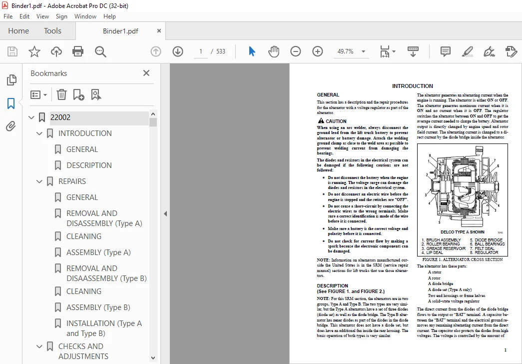
Hyster B177 (H2.00-3.00XL Europe) Service Manual – PDF DOWNLOAD
Original price was: $98.95.$29.95Current price is: $29.95.
Hyster B177 (H2.00-3.00XL Europe) Service Manual – PDF DOWNLOAD
Instant PDF Download
Available immediately
Save to Your Device
Download & keep forever
Antivirus Scanned
100% virus-free
Trusted Worldwide
175,000+ customers
Description
Hyster B177 (H2.00-3.00XL Europe) Service Manual – PDF DOWNLOAD
FILE DETAILS:
Hyster B177 (H2.00-3.00XL Europe) Service Manual – PDF DOWNLOAD
Language : English
Pages : 533
Downloadable : Yes
File Type : PDF
Size: 15.9 MB
TABLE OF CONTENTS:
Hyster B177 (H2.00-3.00XL Europe) Service Manual – PDF DOWNLOAD
22002.............................................................................................................  1
	INTRODUCTION..................................................................................................  1
		GENERAL...................................................................................................  1
		DESCRIPTION...............................................................................................  1
	REPAIRS.......................................................................................................  3
		GENERAL...................................................................................................  3
		REMOVAL AND DISASSEMBLY (Type A)..........................................................................  3
		CLEANING..................................................................................................  3
		ASSEMBLY (Type A).........................................................................................  4
		REMOVAL AND DISAASSEMBLY (Type B).........................................................................  6
		CLEANING..................................................................................................  8
		ASSEMBLY (Type B).........................................................................................  8
		INSTALLATION (Type A and Type B)..........................................................................  9
	CHECKS AND ADJUSTMENTS........................................................................................  9
		GENERAL...................................................................................................  9
		CHECK THE ALTERNATOR FOR LOW OUTPUT (Type A or Type B).................................................... 10
		CHECK THE ALTERNATOR FOR HIGH OUTPUT (Type A or Type B)................................................... 11
		CHECK THE CIRCUIT FOR THE BRUSHES......................................................................... 13
			Delco Alternators..................................................................................... 13
			Motorola Alternators.................................................................................. 13
		CHECK THE DIODES.......................................................................................... 13
		CHECK THE DIODE BRIDGE.................................................................................... 13
			Delco and Leece–Neville Alternators................................................................... 13
			Motorola Alternators.................................................................................. 13
		CHECK THE FIELD WINDING FOR THE ROTOR..................................................................... 14
		CHECK THE WINDINGS IN THE STATOR.......................................................................... 14
		CHECK THE VOLTAGE REGULATOR............................................................................... 15
	TROUBLESHOOTING............................................................................................... 15
60066............................................................................................................. 16
	MAZDA M4-121G ENGINE.......................................................................................... 16
		GENERAL................................................................................................... 16
		DESCRIPTION............................................................................................... 17
		REMOVAL AND INSTALLATION OF THE ENGINE.................................................................... 17
		CYLINDER HEAD AND VALVE MECHANISM......................................................................... 17
			Cylinder Head, Removal................................................................................ 17
			Cylinder Head, Inspection and Repairs................................................................. 18
			Rocker Arm Assembly................................................................................... 18
			Valve Guides.......................................................................................... 18
			Valve Seats........................................................................................... 19
			Valves................................................................................................ 19
			Valve Springs......................................................................................... 19
			Cylinder Head, Installation........................................................................... 19
		TIMING GEAR CASE, REMOVAL................................................................................. 20
		TIMING GEAR CASE, INSTALLATION............................................................................ 21
		CAMSHAFT.................................................................................................. 21
			Removal............................................................................................... 21
			Inspection............................................................................................ 22
			Cam Followers, Inspection............................................................................. 22
			Installation.......................................................................................... 22
		CRANKSHAFT AND MAIN BEARINGS.............................................................................. 22
			Crankshaft, Removal................................................................................... 22
			Crankshaft, Inspection And Repair..................................................................... 23
			Main Bearings......................................................................................... 24
			Crankshaft, Installation.............................................................................. 24
		PISTONS AND CONNECTING RODS............................................................................... 25
			Removal............................................................................................... 25
			Disassembly........................................................................................... 25
			Pistons, Inspection And Repair........................................................................ 25
			Piston Rings.......................................................................................... 26
			Piston Pin and Bushing................................................................................ 26
			Connecting Rods and Bearings, Inspection.............................................................. 26
			Pistons and Connecting Rods, Assembly................................................................. 26
			Pistons and Connecting Rods, Installation............................................................. 27
		CYLINDER BLOCK AND CYLINDER LINERS........................................................................ 27
			Cylinder Block, Repairs............................................................................... 27
			Cylinder Liners....................................................................................... 27
		DISTRIBUTOR............................................................................................... 28
			Removal............................................................................................... 28
			Installation.......................................................................................... 28
		OIL PUMP.................................................................................................. 30
			Removal............................................................................................... 30
			Repairs............................................................................................... 30
			Installation.......................................................................................... 31
		GOVERNOR.................................................................................................. 31
			Description........................................................................................... 31
			Removal............................................................................................... 31
			Disassembly........................................................................................... 32
			Assembly.............................................................................................. 33
			Installation.......................................................................................... 34
		COOLANT PUMP.............................................................................................. 34
			Removal............................................................................................... 34
			Disassembly and Repair................................................................................ 35
			Assembly.............................................................................................. 35
			Installation.......................................................................................... 36
		FLYWHEEL.................................................................................................. 36
			Repairs............................................................................................... 36
			Installation.......................................................................................... 36
	CHECKS AND ADJUSTMENTS........................................................................................ 36
		ADJUST THE VALVES......................................................................................... 36
		ADJUST THE THROTTLE LINKAGE............................................................................... 37
	ENGINE SPECIFICATIONS......................................................................................... 37
		ENGINE SPECIFICATIONS..................................................................................... 37
			Engine Data........................................................................................... 37
			Cooling System........................................................................................ 37
			Cylinder Head and Valve Mechanism..................................................................... 37
			Camshaft.............................................................................................. 39
			Timing Gear........................................................................................... 40
			Camshaft.............................................................................................. 40
			Connecting Rods....................................................................................... 40
			Cylinder Liners....................................................................................... 40
			Pistons............................................................................................... 40
			Lubrication System.................................................................................... 41
			Fuel Pump............................................................................................. 41
		TORQUE SPECIFICATIONS..................................................................................... 42
	TROUBLESHOOTING............................................................................................... 43
60070............................................................................................................. 47
	INTRODUCTION ................................................................................................. 47
		GENERAL .................................................................................................. 47
		DESCRIPTION .............................................................................................. 47
		FUEL SYSTEM .............................................................................................. 48
			Description .......................................................................................... 48
			Operation, Fuel Injection Pump, Model VE ............................................................. 50
			Operation, Fuel Injection Pump, Model PE4A ........................................................... 51
			Pneumatic Governor For Fuel Injection Pump, Model PE4A ............................................... 52
			Inlet Manifold For Fuel Injection Pump, Model PE4A ................................................... 53
	REPAIRS ...................................................................................................... 54
		FUEL INJECTION PUMP (ALL MODELS) ......................................................................... 54
			Removal .............................................................................................. 54
			Installation ......................................................................................... 54
		REMOVAL AND INSTALLATION OF THE ENGINE ................................................................... 54
		CYLINDER HEAD AND VALVE MECHANISM ........................................................................ 54
			Cylinder Head, Removal ............................................................................... 54
			Valve Guides, Replacement ............................................................................ 55
			Cylinder Head, Inspection And Repair ................................................................. 56
			Combustion Chamber Plugs, Inspection And Repair ...................................................... 56
			Combustion Chamber Plugs, Installation ............................................................... 56
			Valves, Inspection And Repair ........................................................................ 57
			Valve Seat, Inspection ............................................................................... 57
			Valve Seat, Removal .................................................................................. 58
			Valve Seat, Installation ............................................................................. 58
			Valve Spring, Inspection ............................................................................. 58
			Rocker Arms, Inspection And Assembly ................................................................. 58
			Installation Of The Cylinder Head .................................................................... 59
		TIMING GEAR CASE ......................................................................................... 60
			Removal .............................................................................................. 60
			Installation ......................................................................................... 60
		CAMSHAFT ................................................................................................. 62
			Removal .............................................................................................. 62
			Inspection ........................................................................................... 62
			Camshaft Bearings .................................................................................... 63
			Cam Followers ........................................................................................ 63
		CAMSHAFT, INSTALLATION ................................................................................... 63
		CRANKSHAFT AND MAIN BEARINGS ............................................................................. 64
			Crankshaft, Removal .................................................................................. 64
			Crankshaft, Inspection And Repair .................................................................... 64
			Main Bearings ........................................................................................ 64
			Pilot Bearing ........................................................................................ 65
			Crankshaft, Installation ............................................................................. 65
		FLYWHEEL AND RING GEAR, H2.00–3.20XM (H40–65XM) .......................................................... 67
			Flywheel, Removal .................................................................................... 67
			Ring Gear, Replacement ............................................................................... 67
			Flywheel, Installation ............................................................................... 67
		PISTONS AND CONNECTING RODS .............................................................................. 68
			Pistons And Connecting Rods, Removal ................................................................. 68
			Disassembly .......................................................................................... 68
			Pistons, Inspection And Repair ....................................................................... 69
			Piston Rings, Inspection And Repair .................................................................. 69
			Piston Pins, Inspection And Repair ................................................................... 70
			Connecting Rods, Inspection And Repair ............................................................... 71
			Pistons And Connecting Rods, Assembly And Installation ............................................... 71
		CYLINDER BLOCK AND CYLINDER LINERS ....................................................................... 71
			Cylinder Liners, Inspection .......................................................................... 71
			Replacement Of A Cylinder Liner ...................................................................... 72
		LUBRICATION SYSTEM ....................................................................................... 73
			Oil Pump, Removal And Disassembly .................................................................... 73
			Oil Pump, Inspection ................................................................................. 73
			Oil Pump, Assembly And Installation .................................................................. 74
			Oil Filter ........................................................................................... 74
		COOLING SYSTEM ........................................................................................... 75
			Coolant Pump, Removal ................................................................................ 75
			Coolant Pump, Disassembly ............................................................................ 75
			Coolant Pump, Assembly And Installation .............................................................. 75
			Thermostat, Replacement .............................................................................. 76
	CHECKS AND ADJUSTMENTS ....................................................................................... 76
		VALVE CLEARANCE ADJUSTMENT ............................................................................... 76
		CHECK THE TIMING OF THE FUEL INJECTION PUMP, MODEL VE .................................................... 77
		CHECK THE TIMING OF THE FUEL INJECTION PUMP, MODEL PE4A .................................................. 78
		FUEL INJECTORS ........................................................................................... 78
			Fuel Injectors, Removal .............................................................................. 79
			Fuel Injectors, Inspection ........................................................................... 79
			Fuel Injectors, Installation ......................................................................... 80
		DIESEL FUEL FILTERS ...................................................................................... 80
			Filter Replacement, Models With A Water Separator .................................................... 80
			Filter Replacement, Models Without A Water Separator ................................................. 81
			Filter For The Fuel Injection Pump, Model PE4A ....................................................... 81
		REMOVE AIR FROM THE FUEL SYSTEM .......................................................................... 81
			Throttle Linkage, Adjustment ......................................................................... 82
			Idle Speed, Adjustment ............................................................................... 82
			Check The Elements For The Cold Start Aid System ..................................................... 82
	ENGINE SPECIFICATIONS ........................................................................................ 82
	TORQUE SPECIFICATIONS ........................................................................................ 84
90015............................................................................................................. 85
	THE LPG FUEL SYSTEM (IMPCO CA 50, CA 100)..................................................................... 85
		GENERAL................................................................................................... 85
		DESCRIPTION............................................................................................... 85
			Fuel Tank............................................................................................. 86
			Fuel Filter And Fuel Valve Unit....................................................................... 87
			Vaporizer............................................................................................. 87
			The IMPCO CA 100 Carbureto............................................................................ 89
			IMPCO CA 50 Carburetor................................................................................ 91
			The Governor (GM Engines Only)........................................................................ 92
			Governor With Electronic Controller................................................................... 93
	REPAIRS....................................................................................................... 94
		LPG TANK.................................................................................................. 94
			Removal............................................................................................... 94
			Installation.......................................................................................... 95
		REPLACE THE HOSES......................................................................................... 95
		HYDROSTATIC RELIEF VALVE.................................................................................. 95
			Removal and Installation.............................................................................. 95
		FILTER UNIT............................................................................................... 96
			Replacement Of the Fuel Filter Element................................................................ 96
			Replacement of the Diaphragm and Fuel Valve........................................................... 97
		VAPORIZER................................................................................................. 97
			Removal............................................................................................... 97
			Disassembly........................................................................................... 97
			Cleaning.............................................................................................. 97
			Inspection............................................................................................ 97
			Assembly.............................................................................................. 99
			Installation.......................................................................................... 99
		CARBURETOR (IMPCO CA 100).................................................................................101
			Removal...............................................................................................101
			Disassembly...........................................................................................101
			Cleaning..............................................................................................101
			Assembly..............................................................................................101
			Installation..........................................................................................104
		CARBURETER (IMPCO CA 50)..................................................................................103
			Removal...............................................................................................103
			Disassembly...........................................................................................103
			Cleaning..............................................................................................104
			Inspection............................................................................................104
			Assembly (See FIGURE 26.).............................................................................104
			Installation..........................................................................................104
	CHECKS AND ADJUSTMENTS........................................................................................105
		CHECK THE FILTER UNIT.....................................................................................105
		CHECK THE VAPORIZER.......................................................................................105
			Pressure Reducer Valve................................................................................105
			Vapor Valve...........................................................................................105
		ADJUST THE CARBURETOR.....................................................................................105
			Idle Mixture..........................................................................................105
			Idle Speed............................................................................................105
			Power Mixture.........................................................................................105
		ADJUST THE GOVERNOR (GM Engines Only).....................................................................106
			Checks................................................................................................106
			Main Adjusting Screw..................................................................................106
			Secondary Adjusting Screw.............................................................................106
			AISAN Governor........................................................................................107
			Adjustment, AISAN Governor............................................................................107
	TROUBLESHOOTING...............................................................................................108
100137............................................................................................................112
	INTRODUCTION..................................................................................................112
		GENERAL...................................................................................................112
		DESCRIPTION...............................................................................................112
	REPAIRS.......................................................................................................112
		COUNTERWEIGHT.............................................................................................113
			Removal...............................................................................................113
			Installation..........................................................................................113
		MUFFLER...................................................................................................114
		HOOD......................................................................................................114
			Removal...............................................................................................114
			Installation..........................................................................................114
		RADIATOR AND COOLANT SYSTEM...............................................................................114
			Removal...............................................................................................114
			Installation..........................................................................................114
		OVERHEAD GUARD............................................................................................115
			Removal And Installation..............................................................................115
		OPERATOR RESTRAINT SYSTEM.................................................................................115
		ENGINE REMOVAL AND INSTALLATION...........................................................................116
			Removal of the Engine and Transmission................................................................116
			Installation of the Engine and Transmission...........................................................120
		FUEL AND HYDRAULIC TANKS..................................................................................122
			Inspection............................................................................................122
			Repairs, Small Leaks..................................................................................122
			Repairs, Large Leaks..................................................................................122
			Cleaning..............................................................................................122
			Steam Method Of Cleaning..............................................................................122
			Chemical Solution Method of Cleaning..................................................................123
			Additional Preparations For Repair....................................................................123
		SAFETY LABELS.............................................................................................123
		CAB.......................................................................................................125
			Cab Replacement.......................................................................................125
			Window Replacement....................................................................................125
			Windshield Wipers and Heater..........................................................................127
140085............................................................................................................128
	INTRODUCTION..................................................................................................128
		GENERAL...................................................................................................128
		DESCRIPTION...............................................................................................128
	REPAIRS.......................................................................................................129
		REMOVAL...................................................................................................129
		CLEANING..................................................................................................129
		INSPECTION................................................................................................129
		ASSEMBLY..................................................................................................129
	TROUBLESHOOTING...............................................................................................132
	SPECIFICATIONS................................................................................................132
160010............................................................................................................133
	INTRODUCTION..................................................................................................133
		DESCRIPTION...............................................................................................133
		GENERAL...................................................................................................133
	REPAIRS.......................................................................................................134
		STEERING AXLE.............................................................................................134
		Removal...................................................................................................134
		Installation..............................................................................................135
		STEERING CYLINDER.........................................................................................135
		Removal...................................................................................................135
		Service...................................................................................................136
		Installation..............................................................................................136
		HUBS......................................................................................................136
		Removal...................................................................................................136
		Installation..............................................................................................137
		SPINDLES..................................................................................................137
		Removal...................................................................................................137
		Installation..............................................................................................138
	CHECKS AND ADJUSTMENTS........................................................................................138
		REMOVE THE AIR FROM THE STEERING SYSTEM...................................................................138
		SET THE PRESSURE RELIEF VALVE.............................................................................138
		S/H1.25-1.75XL (S/H25-35XL) and H2.00-3.00XL (H40-60XL)...................................................138
		H2.00-3.00J (H40-60J) WITH OIL CLUTCH TRANSMISSION........................................................138
		H2.00-3.00J (H40-60J) With Powershift Transmission........................................................138
	TROUBLESHOOTING...............................................................................................140
200077............................................................................................................141
	INTRODUCTION..................................................................................................141
		GENERAL...................................................................................................141
		DESCRIPTION...............................................................................................141
		OPERATION.................................................................................................142
			Lift Section..........................................................................................143
			Tilt Section..........................................................................................143
			Relief Valve..........................................................................................145
		SOLENOID VALVE FOR AUXILIARY FUNCTION.....................................................................146
			Operation.............................................................................................146
	REPAIRS.......................................................................................................146
		MAIN CONTROL VALVE........................................................................................146
			Removal and Disassembly...............................................................................146
			Cleaning and Inspection...............................................................................147
			Assembly..............................................................................................147
			Installation..........................................................................................147
		SOLENOID VALVE FOR AUXILIARY FUNCTION.....................................................................147
			Removal and Disassembly...............................................................................147
			Assembly and Installation.............................................................................149
	CHECKS AND ADJUSTMENTS........................................................................................149
		PRESSURE RELIEF VALVES....................................................................................149
			Primary Relief Valve..................................................................................149
			Seconday Relief Valve.................................................................................150
		CONTROL LEVER ARRANGEMENT.................................................................................150
	TROUBLESHOOTING...............................................................................................153
	SPECIFICATIONS................................................................................................155
700626............................................................................................................156
	COOLING SYSTEM................................................................................................156
		INTRODUCTION..............................................................................................156
		DESCRIPTION...............................................................................................156
		RADIATOR..................................................................................................156
		RADIATOR CAP..............................................................................................156
		THERMOSTAT................................................................................................156
		WATER PUMP................................................................................................157
		FAN AND FAN SHROUD .......................................................................................157
	REPAIRS.......................................................................................................157
		COOLING SYSTEM CHECKS.....................................................................................157
			Exhaust Leaks.........................................................................................157
		RADIATOR..................................................................................................157
			Checks................................................................................................157
			Cleaning The Radiator.................................................................................157
			Drain The Cooling System..............................................................................159
			Fill The Cooling System...............................................................................159
		WATER PUMP................................................................................................159
			Checks................................................................................................159
		THERMOSTAT................................................................................................160
			Checks................................................................................................160
		FAN AND FAN SHROUD .......................................................................................160
	TROUBLESHOOTING...............................................................................................161
800048............................................................................................................162
	LIFT TRUCK WEIGHTS*...........................................................................................162
	ENGINE SPECIFICATIONS.........................................................................................162
	ENGINE ELECTRICAL SPECIFICATIONS..............................................................................163
	HYDRAULIC SPECIFICATIONS......................................................................................163
	CAPACITIES....................................................................................................164
	LIFT TRUCK TRAVEL SPEEDS......................................................................................164
	TIRE SPECIFICATIONS...........................................................................................164
	MAST SPEEDS (Early A177* Units)...............................................................................165
	MAST SPEEDS (Later A177* Units)...............................................................................165
	MAST SPEEDS (B177* and C177* with Mazda M4-121G or Isuzu 240 Engines).........................................166
	MAST SPEEDS (C177* with GM 4-181 or Isuzu 4JB1 Engines).......................................................166
	TORQUE SPECIFICATIONS.........................................................................................168
	TORQUE SPECIFICATIONS.........................................................................................169
900129............................................................................................................171
	THE CARBURETOR, (MAZDA M4-121G ENGINE)........................................................................171
		DESCRIPTION...............................................................................................171
		REPAIRS, CARBURETOR.......................................................................................172
			Removal...............................................................................................172
			Cleaning..............................................................................................175
			Inspection............................................................................................175
			Assembly..............................................................................................175
			Installation..........................................................................................177
		CHECKS AND ADJUSTMENTS....................................................................................177
			Carburetor, Idle Speed And Mixture Adjustment.........................................................177
			Adjust The Governor...................................................................................178
		ADJUST THE THROTTLE LINKAGE...............................................................................179
	SPECIFICATIONS................................................................................................179
	TROUBLESHOOTING...............................................................................................180
1300255...........................................................................................................182
	INTRODUCTION..................................................................................................182
		GENERAL...................................................................................................182
	DESCRIPTION AND OPERATION.....................................................................................183
		GENERAL...................................................................................................183
		TORQE CONVERTER...........................................................................................183
			Description...........................................................................................183
			Operation.............................................................................................183
		CLUTCH ASSEMBLIES.........................................................................................186
			Description...........................................................................................186
			Operation.............................................................................................188
		HYDRAULIC SYSTEM..........................................................................................188
			General...............................................................................................188
		CONTROL VALVE.............................................................................................188
			Regulator for Clutch Pressure.........................................................................191
			Inching Spool Assembly................................................................................191
			Direction Spool.......................................................................................191
			MONOTROL Control Valve................................................................................191
			Neutral Start Switch, MONOTROL Pedal Only.............................................................192
			Neutral Start Switch, Direction Control Lever Only....................................................192
			Modulator Circuit.....................................................................................192
			Regulator for the Toruqe Converter....................................................................193
			By-Pass Valve for the Oil Cooler......................................................................193
		DIFFERENTIAL..............................................................................................194
		OIL FLOW DIAGRAMS.........................................................................................194
1300256...........................................................................................................203
	INTRODUCTION..................................................................................................203
		GENERAL...................................................................................................203
	REPAIRS.......................................................................................................205
		REPAIRS...................................................................................................205
			Torque Converter, Removal.............................................................................205
			Torque Converter, Installation........................................................................205
			Front Cover And Transmission Pump, Removal and Disassembly............................................206
			Front Cover And Transmission Pump, Assembly and Installation..........................................206
			Clutch Assemblies, Removal and Disassembly............................................................207
			Clutch Assemblies, Inspection.........................................................................210
			Clutch Assemblies, Assembly and Installation..........................................................211
			Differential, Removal and Disassembly.................................................................214
			Differential, Inspection..............................................................................216
			Differential, Assembly And Installation...............................................................216
		CONTROL VALVE.............................................................................................226
			Control Valve, Removal and Disassembly................................................................226
			Control Valve, Inspection.............................................................................226
			Control Valve, Assembly and Installation..............................................................228
			MONOTROL Pedal, Removal and Disassembly...............................................................230
			MONOTROL Pedal, Assembly and Installation.............................................................230
	CHECKS AND ADJUSTMENTS........................................................................................232
		Stall Test................................................................................................232
		Adjustment Of The Direction Control Linkage...............................................................233
		Adjustment Of The Brake Pedal And Inching Pedal (Serial Number Codes A177, A187, B10, and C1).............234
		Adjustment Of The Direction Control Linkage (Serial Number Codes B177, C177, B187, and C187)..............237
		Test The Direction Control Linkage (Serial Number Codes B177, C177, B187, and C187).......................238
		Adjustment Of The Inching/Brake Pedal (Serial Number Codes B177, C177, B187, and C187)....................239
		Adjustment Of The Neutral Start Switch, MONOTROL Pedal (Serial Number Codes B177, C177, B187 and C187)....243
		Test The Neutral Start Switch, MONOTROL Pedal (Serial Number Codes B177, C177, B187, and C187)............244
		Check The Oil Pressures...................................................................................244
		Check The Relief Valve for the Transmission Pump..........................................................244
		Check The Clutch Pressure.................................................................................244
		Check The Torque Converter Regulator......................................................................245
		Check The Oil Pressure from the Oil Cooler................................................................245
		Check The Modulator Pressure..............................................................................246
	TROUBLESHOOTING...............................................................................................246
	TROUBLESHOOTING, PRESSURE TESTS...............................................................................248
1600459...........................................................................................................251
	THE STEERING SYSTEM...........................................................................................251
		GENERAL...................................................................................................251
		DESCRIPTION...............................................................................................251
			Hydraulic Pump Assembly...............................................................................252
			Flow Control Valve....................................................................................253
			Relief Valve..........................................................................................253
		OPERATION.................................................................................................253
			Steering System.......................................................................................253
			Hydraulic Pump........................................................................................254
			Flow Control Valve....................................................................................254
			Relief Valve..........................................................................................254
		STEERING WHEEL AND COLUMN ASSEMBLY........................................................................255
			Removal (Serial Code C177 And C187)...................................................................255
			Installation (Serial Code C177 And C187)..............................................................255
			Removal (Serial Code B177 And B187)...................................................................258
			Installation (Serial Code B177 And B187)..............................................................258
		STEERING CONTROL UNIT.....................................................................................259
			Description...........................................................................................259
			Operation, Control Valve Section......................................................................259
			Operation, Metering Section...........................................................................260
		CHECKS AND ADJUSTMENTS....................................................................................260
			Remove Air From The Steering System...................................................................260
			Check And Adjust Steering Relief Pressure.............................................................260
			Check Hydraulic Pump For Correct Flow.................................................................260
	TROUBLESHOOTING...............................................................................................261
1800458...........................................................................................................262
	INTRODUCTION..................................................................................................262
		GENERAL...................................................................................................262
	SERVICE BRAKES AND PARKING BRAKE..............................................................................262
		DESCRIPTION AND OPERATION.................................................................................262
			Service Brakes........................................................................................262
			Parking Brake.........................................................................................263
		REMOVAL AND DISASSEMBLY OF THE 260 mm (10.25 in) SERVICE BRAKES...........................................263
			Parking Brake.........................................................................................265
		CLEANING..................................................................................................266
		INSPECTION................................................................................................266
		ASSEMBLY AND INSTALLATION OF THE 260 mm (10.25 in) SERVICE BRAKES.........................................266
			Adjustments...........................................................................................269
			Parking Brake Installation............................................................................270
			Adjust The Parking Brake For Lift Trucks With 260 mm (10.25 in) Service Brakes........................270
		REMOVAL AND DISASSEMBLY OF THE 310 mm (12.20 in) SERVICE BRAKES...........................................272
			Parking Brake.........................................................................................274
		CLEANING..................................................................................................275
		INSPECTION................................................................................................275
		ASSEMBLY AND INSTALLATION OF THE 310 mm (12.20 in) SERVICE BRAKES.........................................275
			Adjustments...........................................................................................277
			Parking brake.........................................................................................278
			Adjust The Parking Brake For Lift Trucks With 310 mm (12.20 in) Service Brakes........................278
		MASTER CYLINDER...........................................................................................279
			Removal...............................................................................................279
			Repair................................................................................................279
			Installation..........................................................................................279
			Cleaning And Inspection...............................................................................281
		MASTER CYLINDER WITH BRAKE BOOSTER........................................................................283
			Operation.............................................................................................283
			Repair................................................................................................283
	CHECKS AND ADJUSTMENTS........................................................................................285
		ADJUST THE SERVICE BRAKES.................................................................................285
		TEST THE PARKING BRAKE SWITCH (MONOTROL PEDAL ONLY).......................................................285
		REMOVE THE AIR FROM THE BRAKE SYSTEM......................................................................286
		ADJUST THE INCHING/BRAKE PEDAL............................................................................286
		ADJUSTMENT OF THE NEUTRAL START SWITCH (LIFT TRUCKS WITH MONOTROL PEDAL)..................................291
		TEST THE NEUTRAL START SWITCH (MONOTROL PEDAL)............................................................291
			Test 1................................................................................................291
			Test 2................................................................................................292
	TORQUE SPECIFICATIONS.........................................................................................292
	TROUBLESHOOTING...............................................................................................292
1900130...........................................................................................................295
	INTRODUCTION..................................................................................................295
		GENERAL...................................................................................................295
		DESCRIPTION...............................................................................................297
			Hydraulic System......................................................................................297
			Gear Pump Assembly....................................................................................297
			Flow Control Valve....................................................................................298
			Relief Valve (Early Model)............................................................................298
			Relief Valve (Later Model)............................................................................298
		OPERATION.................................................................................................300
			Hydraulic System......................................................................................300
			Gear Pump.............................................................................................300
			Flow Control Valve....................................................................................300
			Relief Valve (Early Model)............................................................................300
			Relief Valve (Later Model)............................................................................300
	REPAIR........................................................................................................302
		GEAR PUMP ASSEMBLY........................................................................................302
			Removal and Disassembly...............................................................................302
			Assembly and Installation.............................................................................303
	CHECKS AND ADJUSTMENTS........................................................................................303
		CHECK AND ADJUST STEERING RELIEF PRESSURE.................................................................303
		CHECK GEAR PUMP FOR CORRECT FLOW..........................................................................304
	TROUBLESHOOTING...............................................................................................304
2100103...........................................................................................................306
	INTRODUCTION..................................................................................................309
		GENERAL...................................................................................................309
		DESCRIPTION...............................................................................................309
	REPAIRS.......................................................................................................309
		REMOVAL...................................................................................................309
		DISASSEMBLY...............................................................................................309
		CLEANING..................................................................................................309
		ASSEMBLY..................................................................................................309
			Tilt Cylinders for the XM and XMS Models..............................................................309
			Tilt Cylinders with O-Ring or Single Lip Seals........................................................311
			Tilt Cylinders for H700-800A and Early Model H700-920B................................................311
		INSTALLATION..............................................................................................311
			Tilt Cylinders with Chevron Packing...................................................................311
	CHECKS AND ADJUSTMENTS........................................................................................315
		CHECK THE TILT CYLINDERS FOR LEAKS........................................................................315
		ADJUST THE TILT CYLINDER STROKE AND THE MAST TILT ANGLE...................................................315
	TROUBLESHOOTING...............................................................................................318
2200106...........................................................................................................321
	INTRODUCTION..................................................................................................321
		GENERAL...................................................................................................321
		DESCRIPTION AND OPERATION.................................................................................321
	REPAIRS.......................................................................................................323
		REMOVAL...................................................................................................323
		DISSASEMBLY...............................................................................................323
		CLEANING..................................................................................................324
		ASSEMBLY..................................................................................................324
		INSTALLATION..............................................................................................324
	CHECKS AND ADJUSTMENTS........................................................................................325
		GENERAL...................................................................................................325
	TROUBLESHOOTING...............................................................................................327
2200132...........................................................................................................329
	INTRODUCTION..................................................................................................329
		GENERAL...................................................................................................329
		DESCRIPTION...............................................................................................329
			Starting System.......................................................................................329
			Ignition System.......................................................................................329
			Charging System.......................................................................................330
	REPAIR........................................................................................................332
		STARTER...................................................................................................332
			Removal And Disassembly...............................................................................332
			Assembly And Installation.............................................................................332
		BALLAST RESISTOR RELAY (Earlier Production)...............................................................334
		DISTRIBUTOR (Earlier Production With Contact Points)......................................................334
			Removal And Disassembly...............................................................................334
			Assembly And Installation.............................................................................336
		COIL REPLACEMENT..........................................................................................336
		DISTRIBUTOR (Later Production with Electronic Ignition System)............................................336
			Removal And Disassembly...............................................................................336
			Assembly And Installation.............................................................................338
		ALTERNATOR (All Models)...................................................................................338
			Removal And Disassembly...............................................................................338
			Assembly And Installation.............................................................................339
		REGULATOR REPLACEMENT (Earlier Production)................................................................340
	CHECKS AND ADJUSTMENTS........................................................................................341
		GENERAL...................................................................................................341
		STARTER...................................................................................................341
			Check Operation.......................................................................................341
			Check Brush Length....................................................................................342
			Check Brush Holder....................................................................................342
			Armature..............................................................................................342
			Field Windings........................................................................................342
			Clutch And Bearing....................................................................................342
		BALLAST RESISTOR RELAY (Earlier Production)...............................................................342
		DISTRIBUTOR...............................................................................................343
			Distributor Contact Clearance.........................................................................343
		SPARK PLUGS...............................................................................................344
		COIL AND BALLAST RESISTOR (Earlier Production)............................................................344
		ALTERNATOR................................................................................................344
			Check For Low Output (Alternator With Separate Regulator).............................................344
			Check For Low Output (Alternator With Integral Regulator).............................................346
			Check For High Output (Alternator With Separate Regulator)............................................347
			Check For High Output (Alternator With Integral Regulator)............................................347
			Rotor Resistance (Alternator with Separate Regulator).................................................347
			Diodes Circuit (Alternator with Separate Regulator)...................................................348
			Diode Assembly (Alternator With Separate Regulator)...................................................348
			Check The Diodes, Diode Trio (Alternator with Integral Regulator).....................................348
			Check The Rectifier Bridge (Alternator with Integral Regulator).......................................349
			Check Field Winding For The Rotor (All Alternators)...................................................349
			Check Windings In The Stator (All Alternators)........................................................350
			Brushes And Bearings..................................................................................350
			Check The Voltage Regulator (Alternator with Separate Regulator)......................................350
			Check The Voltage Regulator (Alternator with Integral Regulator)......................................351
		ADJUSTMENTS...............................................................................................351
	TROBLESHOOTING................................................................................................352
2200134...........................................................................................................354
	INTRODUCTION..................................................................................................354
		GENERAL...................................................................................................354
		DESCRIPTION...............................................................................................354
			Starting System.......................................................................................354
			Charging System.......................................................................................354
			Vacuum Pump On Alternator (On Units With Brake Booster)...............................................356
	REPAIRS.......................................................................................................357
		STARTER...................................................................................................357
			Removal And Disassembly...............................................................................357
			Assembly And Installation.............................................................................357
		REPLACING GLOW PLUGS......................................................................................359
		ALTERNATOR (With Vaccum Pump).............................................................................359
			Removal And Disassembly...............................................................................359
			Cleaning..............................................................................................361
			Assembly And Installation.............................................................................361
		ALTERNATOR (Without Vacuum Pump)..........................................................................362
			Removal And Disassembly...............................................................................362
			Cleaning..............................................................................................364
			Assembly And Installation.............................................................................364
		REGULATOR REPLACEMENT.....................................................................................365
	CHECKS........................................................................................................365
		GENERAL...................................................................................................365
		STARTER...................................................................................................365
			Starter Operation.....................................................................................365
			Solenoid Coil Checks..................................................................................366
			Brush Length..........................................................................................366
			Brush Holder..........................................................................................366
			Armature..............................................................................................366
			Field Windings........................................................................................367
			Clutch And Bearings...................................................................................367
		COLD START AID............................................................................................367
			Glow Plugs............................................................................................367
			Resistor..............................................................................................367
		CHARGING CIRCUIT..........................................................................................367
			Check For Low Output..................................................................................367
			Check Ford High Output................................................................................369
		ALTERNATOR................................................................................................369
			Rotor Resistance......................................................................................369
			Diodes Circuit........................................................................................369
			Rotor Coil............................................................................................370
			Stator Coil...........................................................................................370
			Diode Assembly........................................................................................370
			Brushes And Bearings..................................................................................371
		REGULATOR (At Hydraulic Tank).............................................................................371
	TROUBLESHOOTING...............................................................................................372
2200143...........................................................................................................375
	INTRODUCTION..................................................................................................375
		GENERAL...................................................................................................375
	DESCRIPTION...................................................................................................375
		GENERAL...................................................................................................375
		STEERING COLUMN GAUGES, METERS AND INDICATORS.............................................................378
		LED DISPLAY PANEL.........................................................................................378
			Battery Discharge Indicators .........................................................................378
			Brush Wear Indicators.................................................................................379
			Motor Temperature Indicators..........................................................................380
		"LX" SERIES INSTRUMENT PANEL DISPLAY......................................................................381
			Hourmeter Functions...................................................................................382
			Battery Indicator Function............................................................................382
			Status Code Function..................................................................................382
	CHECKS AND ADJUSTMENTS........................................................................................382
		GENERAL...................................................................................................382
	REPLACEMENT...................................................................................................383
		GENERAL...................................................................................................383
		METER REPLACEMENT.........................................................................................383
		SENDER REPLACEMENT........................................................................................384
			Fuel Level Sender.....................................................................................384
			Pressure And Temperature Sender.......................................................................385
		I.T.W. DISPLAY PANEL......................................................................................385
			Removal...............................................................................................385
	SPECIFICATIONS................................................................................................386
	TROUBLESHOOTING...............................................................................................387
2200144...........................................................................................................388
	ELECTRICAL WARNING DEVICES....................................................................................388
		GENERAL...................................................................................................388
		DESCRIPTION...............................................................................................388
			Operator Controlled Horns.............................................................................388
			System Warning Lights, Buzzers and Bells..............................................................388
			Reverse Warning Horns.................................................................................389
			Warning Lights........................................................................................389
		REPLACEMENT...............................................................................................390
			General...............................................................................................390
			Replacing Horns or Bells..............................................................................390
			Replacing Horn Relay or Buzzer........................................................................390
			Replacing Warning Lights..............................................................................390
			Light Assemblies......................................................................................391
			Replacing Flashing Units..............................................................................391
4000135...........................................................................................................392
	SAFETY PROCEDURES WHEN WORKING NEAR THE MAST..................................................................392
		SAFETY PROCEDURES WHEN WORKING NEAR THE MAST..............................................................392
	LIFT CYLINDERS................................................................................................395
		GENERAL...................................................................................................395
		DESCRIPTION...............................................................................................395
			Lowering Control Valve................................................................................395
			Cylinders (General)...................................................................................398
			Cylinders (H520-620B,H700-800A).......................................................................400
			Cylinders (H360-460B).................................................................................401
			Cylinders (Two-Speed).................................................................................401
	REPAIRS.......................................................................................................402
		REMOVAL OF THE LIFT CYLINDER WITHOUT REMOVING THE MAST....................................................402
			Standard Masts with the Main Lift Cylinder Fastened to the Crossmember of the Inner Mast..............402
			Standard and Full Free-Lift Masts with the Lift Cylinder to a Crosshead...............................406
			Masts that have Two Cylinders, A Main Lift Cylinder  and a Free-Lift Cylinder.........................404
		DISASSEMBLY...............................................................................................404
		ASSEMBLY..................................................................................................406
		INSTALLATION OF THE LIFT CYLINDER IN THE MAST.............................................................406
			Standard Masts with the Main Lift Cylinder Fastened to the Crossmember of the Inner Mast..............406
			Standard and Full-Free-Lift Masts with the Lift Cylinder Fastened to a Crosshead......................406
		CHEVRON PACKING...........................................................................................407
	LIFT CYLINDERS FOR VISTA MASTS................................................................................410
		DESCRIPTION...............................................................................................410
			Lowering Control Valve................................................................................412
		REMOVAL...................................................................................................413
		DISASSEMBLY...............................................................................................413
		ASSEMBLY..................................................................................................413
		INSTALLATION..............................................................................................414
			Main Lift Cylinders...................................................................................414
			Free-Lift Cylinders...................................................................................414
	CHECKS AND ADJUSTMENTS........................................................................................415
		CHECK FOR LEAKS IN LIFT SYSTEM............................................................................415
	TROUBLESHOOTING...............................................................................................416
	SPECIFICATIONS................................................................................................417
4000222...........................................................................................................418
	INTRODUCTION..................................................................................................418
		GENERAL...................................................................................................418
		MAST WELDMENTS............................................................................................418
		CARRIAGE..................................................................................................418
		MAST MOUNTS...............................................................................................419
	VISTA® TWO-STAGE MAST.........................................................................................420
		DESCRIPTION AND OPERATION.................................................................................420
	VISTA® FREE-LIFT MAST.........................................................................................422
		DESCRIPTION...............................................................................................422
		OPERATION.................................................................................................422
	VISTA® THREE-STAGE MAST.......................................................................................424
		DESCRIPTION...............................................................................................424
		OPERATION.................................................................................................424
	VISTA® FOUR-STAGE MAST........................................................................................425
		DESCRIPTION...............................................................................................425
		OPERATION.................................................................................................426
4000223...........................................................................................................428
	VISTA MAST, REPAIR............................................................................................428
		GENERAL...................................................................................................428
		SAFETY PROCEDURES WHEN WORKING NEAR THE MAST..............................................................428
		FORKS.....................................................................................................429
			Forks, Removal And Installation.......................................................................429
		CARRIAGE..................................................................................................430
			Removal...............................................................................................430
			Installation..........................................................................................431
		MASTS.....................................................................................................431
			Removal...............................................................................................431
			Disassembly...........................................................................................432
			Cleaning and Inspection...............................................................................437
			Assembly..............................................................................................437
			Installation..........................................................................................441
		SIDE-SHIFT CARRIAGE (EARLIER DESIGN)......................................................................442
			Removal...............................................................................................442
			Repairs...............................................................................................442
			Installation..........................................................................................442
		SIDE-SHIFT CARRIAGE (1993 AND LATER DESIGN)...............................................................443
			Removal...............................................................................................443
			Repairs...............................................................................................443
			Installation..........................................................................................444
	CHECKS AND ADJUSTMENTS........................................................................................445
		CHECK FOR LEAKS IN THE LIFT AND TILT SYSTEM...............................................................445
		ADJUST THE TILT CYLINDER STROKE AND THE BACKWARD TILT ANGLE...............................................446
		LIFT CHAIN ADJUSTMENTS....................................................................................447
		MAST ADJUSTMENTS..........................................................................................447
		CARRIAGE ADJUSTMENT.......................................................................................449
		HEADER HOSE ARRANGEMENTS..................................................................................449
			Two-Stage Header Hose.................................................................................450
			Header Hoses For Free-Lift, Three-Stage, and Four Stage Masts.........................................450
	TROUBLESHOOTING...............................................................................................455
8000231...........................................................................................................456
	INTRODUCTION..................................................................................................456
		NOMENCLATURE, THREADS.....................................................................................456
		STRENGTH IDENTIFICATION...................................................................................457
	TABLE 1. BOLTS AND SCREWS.....................................................................................457
	TABLE 2. STUDS AND NUTS.......................................................................................458
	TABLE 3. TORQUE NUTS..........................................................................................459
	TABLE 4. TORQUE NUTS WITH NYLON INSERT........................................................................460
	TABLE 5. TORQUE VALUES FOR INCH FASTENERS.....................................................................461
	TABLE 6. TORQUE VALUES FOR METRIC FASTENERS...................................................................462
8000259...........................................................................................................465
	PERIODIC MAINTENANCE..........................................................................................465
		GENERAL...................................................................................................465
			Serial Number Data....................................................................................465
		HOW TO MOVE A DISABLED LIFT TRUCK.........................................................................466
			How To Tow the Lift Truck.............................................................................466
		HOW TO PUT A LIFT TRUCK ON BLOCKS.........................................................................466
			How To Raise the Drive Tires..........................................................................466
			How To Raise the Steering Tires.......................................................................467
	MAINTENANCE PROCEDURES........................................................................................471
	EVERY 8 HOURS OR DAILY........................................................................................471
		HOW TO MAKE CHECKS WITH THE ENGINE STOPPED................................................................471
			Engine Oil............................................................................................471
			Drive Belts...........................................................................................471
			Cooling System........................................................................................471
			Battery...............................................................................................472
			Fuel System...........................................................................................474
			Air Filter............................................................................................474
			Hydraulic System Oil..................................................................................474
			Tires and Wheels......................................................................................475
			Forks.................................................................................................475
			Forks, Adjustment.....................................................................................476
			Forks, Removal And Installation.......................................................................476
			Inspection Of Forks, Mast, and Lift Chains............................................................477
			Safety Labels.........................................................................................478
			Operator Restraint System.............................................................................478
		HOW TO MAKE CHECKS WITH THE ENGINE RUNNING................................................................479
			Gauges, Lights, Horn, and Fuses.......................................................................479
			Fuel Filter, Diesel Engine............................................................................480
			How To Drain The Water From The Fuel Filter...........................................................480
			Oil Level, Powershift Transmission....................................................................480
			Control Levers and Pedals.............................................................................480
			Lift System Operation.................................................................................480
			Inching/Brake Pedal...................................................................................481
			Service Brakes........................................................................................481
			Parking Brake.........................................................................................481
			Steering System.......................................................................................481
	EVERY 250 HOURS OR TWO MONTHS.................................................................................482
		ENGINE OIL AND FILTER.....................................................................................482
			Mazda, GM, And Later Production Isuzu Engines.........................................................482
			Earlier Production Isuzu C240 Engines.................................................................482
		GOVERNOR, MAZDA ENGINE....................................................................................483
		DRIVE BELTS...............................................................................................483
			Mazda Engine..........................................................................................483
			Isuzu, GM 4-181, And GM 4-153 Engines.................................................................483
		BRAKE FLUID...............................................................................................484
		HYDRAULIC TANK BREATHER, CLEAN AND CHECK..................................................................484
		FORKS, CHECK FOR WEAR AND DAMAGE..........................................................................484
		LIFT CHAINS...............................................................................................484
			Lubrication...........................................................................................484
			Check For Wear........................................................................................484
		MAST, LUBRICATION.........................................................................................485
		TIE ROD ENDS AND PIVOT SHAFT, STEERING AXLE...............................................................485
		CONTROL LEVERS AND PEDALS, LUBRICATION....................................................................486
		FUEL SYSTEM, CHECKS AND ADJUSTMENTS.......................................................................486
			Idle Speed, Diesel....................................................................................486
			LPG Carburetor........................................................................................487
			Gasoline Carburetor...................................................................................487
	EVERY 1000 HOURS OR SIX MONTHS................................................................................488
		DIESEL FUEL FILTER........................................................................................488
			Filter Replacement, Models Without A Water Separator..................................................489
			Filter Replacement, Models With A Water Separator.....................................................489
			Remove Air from the Diesel Fuel System................................................................489
		DIFFERENTIAL..............................................................................................490
		VALVE CLEARANCE ADJUSTMENT................................................................................490
		IGNITION SYSTEM, MAZDA AND GM ENGINES.....................................................................490
		PCV VALVE AND FILTER......................................................................................492
	EVERY 2000 HOURS OR YEARLY....................................................................................492
		HYDRAULIC SYSTEM..........................................................................................492
			Replace the Hydraulic Oil and Filter..................................................................492
		POWERSHIFT TRANSMISSION...................................................................................492
		COOLING SYSTEM............................................................................................493
		SERVICE BRAKES............................................................................................493
		DIFFERENTIAL..............................................................................................493
		WHEEL BEARINGS............................................................................................494
			Steering Wheels, lubrication..........................................................................494
			Drive Wheels, Lubrication.............................................................................494
		GASOLINE FUEL FILTER, REPLACEMENT.........................................................................494
		PCV VALVE, GM ENGINES.....................................................................................494
		LPG FILTER, REPLACEMENT...................................................................................494
		FILTER FOR THE FUEL INJECTION PUMP, MODEL PE4A............................................................494
	GENERAL PROCEDURES............................................................................................495
		CHECK THE HOOD LATCH......................................................................................495
		LIFT CHAIN ADJUSTMENTS....................................................................................495
		SAFETY PROCEDURES WHEN WORKING NEAR THE MAST..............................................................497
		CHECK FOR LEAKS IN THE LIFT AND TILT SYSTEM...............................................................498
			Check the Lift Cylinders for Leaks....................................................................498
			Check the Tilt Cylinders for Leaks....................................................................498
		FUEL INJECTORS............................................................................................499
		WELDING REPAIRS...........................................................................................499
		CHANGES TO THE OVERHEAD GUARD.............................................................................499
		WHEELS AND TIRES..........................................................................................499
			Solid Rubber Tires (Press-on).........................................................................499
			Install The Wheels....................................................................................500
			Pneumatic Tires, Remove The Wheels From The Lift Truck................................................501
			Pneumatic Tires, Remove the Tire From The Wheel.......................................................501
			Pneumatic Tires, Install The Wheel In The Tire........................................................502
			Pneumatic Tires, Add Air To The Tires.................................................................503
			Pneumatic Tires, Install the Wheels...................................................................504
			Pneumatic Tires, Installation Procedures, Dual Drive Wheels...........................................504
		SOLID RUBBER TIRES THAT LOOK LIKE PNEUMATIC TIRES.........................................................505
			Remove The Wheels From The Lift Truck.................................................................505
			Remove The Tire From The Wheel........................................................................505
			Install The Tire On The Wheel.........................................................................506
	REFERENCE TABLE...............................................................................................507
8000461...........................................................................................................508
	FIGURE 1. HYDRAULIC SYSTEM SCHEMATIC..........................................................................509
	FIGURE 2. TRANSMISSION SCHEMATIC..............................................................................510
	FIGURE 3. INSTRUMENT PANEL ELECTRICAL DIAGRAM.................................................................511
	FIGURE 4. MAZDA ENGINE, GASOLINE/LPG WIRING SCHEMATIC.........................................................513
	FIGURE 5. MAZDA ENGINE, GASOLINE/LPG CABLE DIAGRAM (G and LPG Rating).........................................515
	FIGURE 6. MAZDA ENGINE, GASOLINE/LPG CABLE DIAGRAM (GS and LPS Rating)........................................517
	FIGURE 7. DIESEL ENGINE WIRING SCHEMATIC......................................................................519
	FIGURE 8. DIESEL ENGINE CABLE DIAGRAM (D Rating)..............................................................521
	FIGURE 9. DIESEL (SAFETY) ENGINE CABLE DIAGRAM (DS RATING)....................................................523
	FIGURE 10. GM ENGINE, GASOLINE/LPG WIRING DIAGRAM (GS and LPS Rating).........................................525
	FIGURE 11. GM ENGINE, GASOLINE/LPG CABLE DIAGRAM (G and LPG Rating)...........................................527
	FIGURE 12. GM ENGINE, GASOLINE/LPG CABLE DIAGRAM (GS and LPS Rating)..........................................529
HYSTER B177 (H2.00-3.00XL EUROPE) SERVICE MANUAL – PDF DOWNLOAD:
IMAGES PREVIEW OF THE MANUAL:
PLEASE NOTE:
- This is the same manual used by the DEALERSHIPS to SERVICE your vehicle.
- The manual can be all yours – Once payment is complete, you will be taken to the download page from where you can download the manual. All in 2-5 minutes time!!
- Need any other service / repair / parts manual, please feel free to contact us at heydownloadss @gmail.com . We may surprise you with a nice offer
S.V