Trusted Business
Verified & Licensed
Virus Free Files
100% Safe Downloads
Secure Payment
SSL Protected
Instant Delivery
Available Immediately
Sale!
Hyster C108 Service Manual – PDF DOWNLOAD
Original price was: $89.95.$29.95Current price is: $29.95.
Hyster C108 Service Manual – PDF DOWNLOAD
Instant PDF Download
Available immediately
Save to Your Device
Download & keep forever
Antivirus Scanned
100% virus-free
Trusted Worldwide
175,000+ customers
Description
Hyster C108 Service Manual – PDF DOWNLOAD
FILE DETAILS
Hyster C108 Service Manual – PDF DOWNLOAD
Language : English
Pages : 303
Downloadable : Yes
File Type : PDF
Size: 6.06 MB
TABLE OF CONTENTS:
Hyster C108 Service Manual – PDF DOWNLOAD
1600485......................................................................................................................................... 1
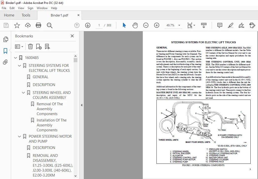
STEERING SYSTEMS FOR ELECTRICAL LIFT TRUCKS................................................................................................. 1
GENERAL................................................................................................................................. 1
DESCRIPTION............................................................................................................................. 3
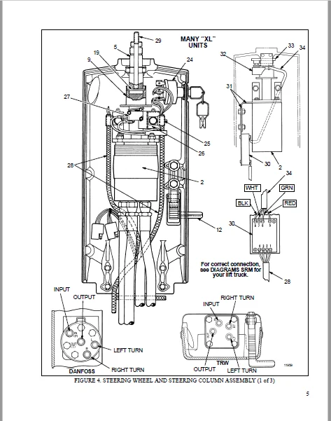
STEERING WHEEL AND COLUMN ASSEMBLY...................................................................................................... 4
Removal Of The Assembly Components.................................................................................................. 4
Installation Of The Assembly Components............................................................................................. 8
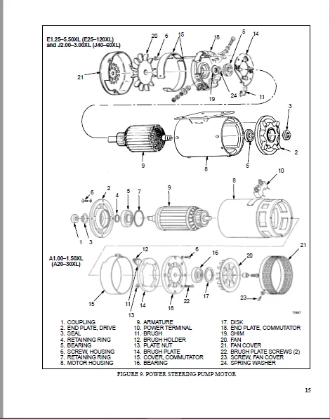
POWER STEERING MOTOR AND PUMP............................................................................................................... 9
DESCRIPTION............................................................................................................................. 9
REMOVAL AND DISASSEMBLY, E1.25-3.00XL (E25-60XL), J2.00-3.00XL (J40-60XL), E2.00-3.20XM (E45-65XM), N30XMH.............................. 9
REMOVAL AND DISASSEMBLY, E3.50-5.50XL (E70-120XL)....................................................................................... 9
REMOVAL AND DISASSEMBLY, J2.00-3.20XM (J40-65XM)........................................................................................ 10
REMOVAL AND DISASSEMBLY, A1.00-1.50XL (A20-30XL)........................................................................................ 12
REMOVAL AND DISASSEMBLY, E1.50-2.00XMS (E25-40XMS)...................................................................................... 13
ASSEMBLY AND INSTALLATION {All models with a vertical mount except the J2.00-3.20XM (J40-65XM)}......................................... 13
ASSEMBLY AND INSTALLATION, J2.00-3.20XM (J40-65XM)...................................................................................... 13
ASSEMBLY AND INSTALLATION, E1.50-2.00XMS (25-40XMS)..................................................................................... 16
REPAIRS, POWER STEERING PUMP............................................................................................................ 17
Seal Replacement.................................................................................................................... 18
HYDRAULIC STEERING MOTOR.................................................................................................................... 18
DESCRIPTION............................................................................................................................. 18
REPAIRS, HYDRAULIC STEERING MOTOR....................................................................................................... 19
Removal............................................................................................................................. 19
Disassembly ........................................................................................................................ 19
Cleaning And Inspection............................................................................................................. 19
Assembly............................................................................................................................ 20
Installation, Hydraulic Steering Motor.............................................................................................. 21
CHECKS AND ADJUSTMENTS...................................................................................................................... 21
AIR IN THE STEERING SYSTEM.............................................................................................................. 21
CHECK STEERING PRESSURE................................................................................................................. 21
CHECK THE TENSION OF THE STEERING CHAIN (Units With MDU Only)........................................................................... 23
CHECK OPTICAL ENCODER AND ACTIVATOR CIRCUITS............................................................................................ 23
TROUBLESHOOTING............................................................................................................................. 25
2200288......................................................................................................................................... 27
EV-100 MOTOR CONTROLLER REPAIRS AND ADJUSTMENTS............................................................................................. 27
GENERAL................................................................................................................................. 27
FUSES................................................................................................................................... 32
CONTROL CARD............................................................................................................................ 33
The Control Card Plugs.............................................................................................................. 35
HOW TO CHECK AN SCR..................................................................................................................... 35
The SCR Assembly.................................................................................................................... 36
Thermal Protector................................................................................................................... 36
How To Replace The SCR 1 Assembly................................................................................................... 36
THE "OFF" CIRCUIT FOR SCR 1............................................................................................................. 37
Check The Inductor Assembly......................................................................................................... 37
Check Suppressors For SCR 2 And SCR 5............................................................................................... 37
Check SCR 2 And SCR 5............................................................................................................... 38
Replace The SCR 2 And SCR 5......................................................................................................... 38
Check Capacitor C1.................................................................................................................. 39
DIODES D3 AND D4........................................................................................................................ 39
Check The Diodes D3 and D4.......................................................................................................... 39
Replacement, Diodes D3 and D4....................................................................................................... 39
MOTOR CURRENT SENSOR.................................................................................................................... 39
THE ELECTRONIC DRIVER MODULE............................................................................................................ 39
CONTACTORS.............................................................................................................................. 40
CONTACTOR REPAIR........................................................................................................................ 41
Removing A Contactor Assembly....................................................................................................... 41
Contactor Contacts.................................................................................................................. 41
Coil................................................................................................................................ 42
CONTROL CARD ADJUSTMENTS................................................................................................................ 44
"CREEP"............................................................................................................................. 44
"C/A" (Controlled Acceleration)..................................................................................................... 44
"C/L"............................................................................................................................... 44
"1A TIME"........................................................................................................................... 45
"PLUG".............................................................................................................................. 46
"F.W.P.U. and "F.W.D.O."............................................................................................................ 46
"REGEN C/L"......................................................................................................................... 46
"REGEN D.O."........................................................................................................................ 46
VOLTAGE ADJUSTMENTS, SCR CONTROL FOR HYDRAULIC PUMP..................................................................................... 46
2200289......................................................................................................................................... 50
INTRODUCTION................................................................................................................................ 50
General................................................................................................................................. 50
Lift Truck Control...................................................................................................................... 50
PRINCIPLES OF OPERATION..................................................................................................................... 51
The Silicon Controlled Rectifier (SCR).................................................................................................. 53
A Motor Circuit That Operates With Pulses............................................................................................... 54
The SCR 1 "OFF" Circuit................................................................................................................. 55
Induction Current From The Motor........................................................................................................ 59
The Logic Box........................................................................................................................... 59
SCR Control (Hydraulic Pump)............................................................................................................ 64
Contactors.............................................................................................................................. 65
Circuit Protection...................................................................................................................... 66
Warning Indicators...................................................................................................................... 66
Sequence of Operation................................................................................................................... 67
2200290......................................................................................................................................... 71
INTRODUCTION................................................................................................................................ 71
General................................................................................................................................. 71
"Static Return To OFF" (SRO) Circuit ................................................................................................... 74
Fault Detector.......................................................................................................................... 74
The Sequence of Operation (Traction Circuit)............................................................................................ 74
Checking for the Correct Operation...................................................................................................... 74
TROUBLESHOOTING............................................................................................................................. 76
General Procedures...................................................................................................................... 76
FAULT NEMBER 1. The Direction Contactors Will Not Close For Operation In Either Direction................................................... 77
FAULT NUMBER 2. The Lift Truck Will Not Move In Either Direction. The Direction Contactors Close and The Immediately Open (72-80............ 80
FAULT NUMBER 2A. The Lift Truck Will Not Move In Either Direction. The Direction Contactors Close and Then Immediately Open (36-............ 82
FAULT NUMBER 3. The Lift Truck Will Not Move In Either Direction. The Direction Contactors Close Normally................................... 84
FAULT NUMBER 4. The Lift Truck Will Only Move In One Direction. In The Other Direction, The Direction Contactor Closes And Then ............ 85
FAULT NUMBER 5. One Direction Contactor Will Not Close. The Traction Circuit Operates Normally In Only One Direction........................ 86
FAULT NUMBER 6. Contactor 1A Will Not Energize. The Other Operations Of The Lift Truck Are Normal. (36-48 Volt Lift Trucks Equi ............ 87
FAULT NUMBER 7. Plugging Problems (Lift Trucks Equipped With Only The Plugging Function).................................................... 88
FAULT NUMBER 8. Regenerative Braking Problems (Lift Trucks Equipped With Regenerative Braking).............................................. 88
FAULT NUMBER 9. The Hydraulic Pump Motor Will Not Operate When Any Hydraulic Hand Lever Is Moved From The Neutral Position. (SCR............ 89
FAULT NUMBER 10. The Hydraulic Pump Will Not Stop Operating When The Hydraulic Hand Levers Are Returned To The Neutral Position............. 91
FAULT NUMBER 11. The Hydraulic Pump Will Not Operate When One Hydraulic Hand Lever Is Moved For A Hydraulic Function. The Operat............ 92
FAULT NUMBER 12. Hydraulic Control Problems (Lift Trucks Equipped With A Hydraulic Pump Contactor).......................................... 93
REPAIRS AND ADJUSTMENTS..................................................................................................................... 94
Fuses................................................................................................................................... 94
Logic Box............................................................................................................................... 94
Check the Components of the "OFF" Circuit............................................................................................... 96
Contactors.............................................................................................................................. 98
Contactor Repair........................................................................................................................ 99
LED Panel Display.......................................................................................................................100
Control Switches........................................................................................................................101
"PLUG"..................................................................................................................................105
Current Limit...........................................................................................................................105
2200312.........................................................................................................................................107
INTRODUCTION................................................................................................................................107
GENERAL.................................................................................................................................107
SRO CIRCUIT AND PMT CIRCUIT (TRACTION CIRCUIT)..............................................................................................110
STATIC RETURN TO OFF (SRO) CIRCUIT......................................................................................................110
PULSE MONITOR TRIP (PMT)................................................................................................................110
THE SEQUENCE OF OPERATION (TRACTION CIRCUIT)............................................................................................110
CHECKING FOR THE CORRECT OPERATION......................................................................................................111
TROUBLESHOOTING.............................................................................................................................112
GENERAL PROCEDURES......................................................................................................................113
FAULT NUMBER 1. The Direction Contactors Will Not Close For Operation In Either Direction...........................................115
LIFT TRUCKS WITHOUT REGENERATIVE BRAKING....................................................................................................115
GENERAL PROCEDURES......................................................................................................................113
FAULT NUMBER 2. Lift Truck Will Not Move In Either Direction. The Direction Contactors Close And Then Immediately Open (PMT Fau....118
FAULT NUMBER 3. Lift Truck Will Not Move In Either Direction. The Direction Contactors Close Normally (No PMT Fault)................120
FAULT NUMBER 4. Lift Truck Will Not Move In One Direction. The Direction Contactors Close Normally (No PMT Fault)...................122
FAULT NUMBER 5. One Direction Contactor Will Not Close. Traction Circuit Operates Normally In Only One Direction...................122
FAULT NUMBER 6. Plugging Problems...................................................................................................123
FAULT NUMBER 7. Direction Contactors Close Normally. The Lift Truck Has Only Low Power Or Moves Slowly.............................124
FAULT NUMBER 8. Contactor 1a Will Not Energize. The Other Operations Of The Lift Truck Are Normal..................................125
FAULT NUMBER 1R. Regenerative Braking Contactor Does Not Close. The "forward" And "reverse" Contactors Will Close. The Lift Tr....126
LIFT TRUCKS EQUIPPED WITH REGENERATIVE BRAKING..............................................................................................126
GENERAL PROCEDURES......................................................................................................................113
FAULT NUMBER 2R. Lift Truck Will Not Move In Either Direction. The Direction Contactors Never Close. The Regenerative Braking ....127
FAULT NUMBER 3R. Lift Truck Will Not Move In One Direction. The Regenerative Braking Contactor Closes Normally. Direction Cont....129
FAULT NUMBER 4R. Lift Truck Will Not Move In Either Direction. The Regenerative Braking Contactor Closes. A Direction Contacto....130
FAULT NUMBER 5R. Lift Truck Will Not Move In Either Direction. The Regenerative Braking Contactor Closes. The Direction Contac....132
FAULT NUMBER 6R. One Direction Contactor Will Not Close. The Regenerative Braking Contactor Closes Normally. The Traction Circ....134
FAULT NUMBER 7R. Direction Contactors Close Normally. The Lift Truck Has Only Low Power Or Moves Slowly. The Regenerative Brak....136
FAULT NUMBER 8R. Contactor 1a Will Not Energize. The Other Operations Of The Lift Truck Are Normal.................................137
FAULT NUMBER 9R. The Field Weakening Contactor Will Not Energize (36-48 Volt Lift Trucks Only). The Other Operations Of The Lif....138
FAULT NUMBER 10R. Regenerative Braking And Plugging Problems........................................................................139
FAULT NUMBER 11R. The Hydraulic Pump Will Not Operate When Any Hydraulic Hand Lever Is Moved From The Neutral Position..............140
FAULT NUMBER 12R. The Hydraulic Pump Will Not Stop Operating When The Hydraulic Hand Levers Are Returned To The Neutral Position....141
FAULT NUMBER 13R. The Hydraulic Pump Will Not Operate When Only One Hydraulic Lever Is Moved From The Neutral Position. The Ope....142
2200460.........................................................................................................................................143
INTRODUCTION................................................................................................................................143
General.................................................................................................................................143
DESCRIPTION.................................................................................................................................143
Diagnostic Control Card.................................................................................................................143
Status Codes........................................................................................................................145
Hand Set................................................................................................................................145
Instrument Panel Display................................................................................................................146
Hourmeter Functions.................................................................................................................146
Battery Indicator Functions.........................................................................................................146
Control Card Connections................................................................................................................147
CHECKS AND ADJUSTMENTS......................................................................................................................153
General.................................................................................................................................153
Function Codes......................................................................................................................153
Connecting The Control Card For Bench Checks And Adjustments........................................................................154
Connecting The Hand Set To A Control Card Installed In A Lift Truck.................................................................155
Checking And Adjusting Function Settings................................................................................................155
General.............................................................................................................................155
How To Connect And Check Hand Set ..................................................................................................155
How To Check And Adjust Functions...................................................................................................155
Function Descriptions...............................................................................................................156
Traction Control Cards (EV-100/200 LXT-LX)..........................................................................................156
Pump Control Card (EV-100/200 LXP)..................................................................................................160
Dual Motor Traction Control Card (EV-100 LXM).......................................................................................161
Function Tables.........................................................................................................................164
REPAIRS.....................................................................................................................................177
General.................................................................................................................................177
Control Card Plugs......................................................................................................................177
TROUBLESHOOTING.............................................................................................................................178
General.................................................................................................................................178
2200464.........................................................................................................................................213
ELECTRICAL CHECKS AND ADJUSTMENTS FOR SitDrive) ELECTRICAL LIFT TRUCKS......................................................................213
GENERAL.................................................................................................................................213
CONTROL AND POWER FUSES.................................................................................................................218
CONTROL CARD ADJUSTMENTS................................................................................................................219
Adjusting Creep Speed, "CREEP'......................................................................................................221
Adjusting Controlled Acceleration, "C/A" ...........................................................................................221
Adjusting Current Limit, "C/L"......................................................................................................222
Adjust "1A TIME"....................................................................................................................223
Adjust 1A Drop Out, "1A D.O"........................................................................................................225
Adjust Plugging, "PLUG".............................................................................................................225
Ramp Start..........................................................................................................................225
Adjust Field Weakening Pick Up and Drop Out, "F.W.P.U." And "F.W.D.O."..............................................................225
Adjust "REGEN C/L" (Current Limit)..................................................................................................226
Adjust "REGEN D.O." (Drop Out)......................................................................................................226
PROPORTIONAL CONTROL (J25-35A Only).....................................................................................................229
SCR CONTROL, DUAL HYDRAULIC PUMP MOTORS.................................................................................................230
SCR CONTROL, SINGLE PUMP MOTOR..........................................................................................................230
Accelerator Card (E-20-100B, J40-60AS Only).........................................................................................231
Circuit Description For Accelerator Card Used With A Seat Switch....................................................................232
Accelerator "START" (IC3)...........................................................................................................233
Accelertor "1A TIME" (IC2)..........................................................................................................233
Circuit Description For Accelerator Card Used With A Seat Brake.....................................................................233
Accelerator "START" (IC3)...........................................................................................................234
Accelerator "1A TIME" (IC1 and IC2).................................................................................................234
CHECK THE ACCELERTOR CARD...........................................................................................................234
ADJUSTING THE ACCELERATOR CARD......................................................................................................234
THE POTENTIOMETERS AND CONTOL SWITCHES..................................................................................................234
Steering Potentiometer (J25-35A Only)...............................................................................................234
Accelerator Potentiometer And Start Switch (E20-120XL And J25-60XL Only)............................................................236
Accelerator Potentiometer And Direction Switch......................................................................................237
Adjusting Start Switch..............................................................................................................238
"FORWARD" And "REVERSE" Switch (MONOTROL) (Earlier Production Lift Trucks)..........................................................238
Direction Switches (MONOTROL) (Later Production Lift Trucks)........................................................................239
"FORWARD" And "REVERSE" Switch (Steering Column)....................................................................................240
Hydraulic Pump Switch...............................................................................................................240
Replace The Key Switch..............................................................................................................240
Adjust The Seat Switch..............................................................................................................240
Adjust The Brake Switch.............................................................................................................241
Parking Brake Switch................................................................................................................241
Rocker Switch.......................................................................................................................242
HYDRAULIC PUMP SOFT START (E100-120B Only) (72/80 Volt Only)............................................................................243
8000293.........................................................................................................................................244
FIGURE 1. SCHEMATIC DIAGRAM, EV-100 MOTOR CONTROLLER, (AFTER NOVEMBER 1987).................................................................244
FIGURE 2. SCHEMATIC DIAGRAM, BATTERY INDICATOR WITHOUT LIFT INTERRUPT AND SCR CONTROL FOR HYDRAULIC PUMP MOTOR, (AFTER NOVEMBER ............246
FIGURE 3. SCHEMATIC DIAGRAM, BATTERY INDICATOR WITHOUT LIFT INTERRUPT AND WITH CONTACTOR CONTROL FOR HYDRAULIC PUMP MOTOR, (AFTE............247
FIGURE 4. SCHEMATIC DIAGRAM, BATTERY INDICATOR WITH LIFT INTERRUPT AND WITH SCR CONTROL FOR HYDRAULIC PUMP MOTOR, (AFTER NOVEMBE............248
FIGURE 5. SCHEMATIC DIAGRAM, BATTERY INDICATOR WITH LIFT INTERRUPT AND WITH CONTACTOR CONTROL FOR HYDRAULIC PUMP MOTOR, (AFTER N............249
FIGURE 6. SCHEMATIC DIAGRAM, LED DISPLAY WITH LIFT INTERRUPT AND WITH SCR CONTROL FOR HYDRAULIC PUMP MOTOR, (AFTER NOVEMBER 1987............250
FIGURE 7. WIRE DIAGRAM, CONTROL SWITCHES (AFTER NOVEMBER 1987)..............................................................................251
FIGURE 8. WIRE DIAGRAM, EV-100 MOTOR CONTROLLER WITH CONTACTOR CONTROL FOR HYDRAULIC PUMP MOTOR (AFTER NOVEMBER 1987).......................253
FIGURE 9. WIRE DIAGRAM, EV-100 MOTOR CONTROLLER WITH REGENERATIVE BRAKING, SCR CONTROL FOR HYDRAULIC PUMP MOTOR AND FIELD WEAKEN............254
FIGURE 10. WIRE DIAGRAMS, BATTERY INDICATORS (AFTER NOVEMBER 1987)..........................................................................255
FIGURE 11. WIRE DIAGRAMS, BATTERY INDICATORS (AFTER NOVEMBER 1987)..........................................................................256
FIGURE 12. SCHEMATIC DIAGRAM, EV-100 MOTOR CONTROLLER WITH REGENERATIVE BRAKING, (BEFORE NOVEMBER 1987).....................................257
FIGURE 13. SCHEMATIC DIAGRAM, EV-100 MOTOR CONTROLLER WITHOUT REGENERATIVE BRAKING, (BEFORE NOVEMBER 1987)..................................259
FIGURE 14. WIRE DIAGRAM, EV-100 MOTOR CONTROLLER WITH REGENERATIVE BRAKING, (BEFORE NOVEMBER 1987)..........................................261
FIGURE 15. WIRE DIAGRAM, EV-100 MOTOR CONTROLLER WITHOUT REGENERATIVE BRAKING, (BEFORE NOVEMBER 1987).......................................263
FIGURE 16. WIRE DIAGRAM, CONTROL SWITCHES (BEFORE NOVEMBER 1987)............................................................................265
FIGURE 17. WIRE DIAGRAMS, BATTERY INDICATORS (BEFORE NOVEMBER 1987).........................................................................267
FIGURE 18. HYDRAULIC SCHEMATIC, ALL MODELS..................................................................................................268
8000314.........................................................................................................................................269
8000466.........................................................................................................................................281
FIGURE 1. EV-100 "LX" SERIES TRACTION SCHEMATIC DIAGRAM.....................................................................................282
FIGURE 2. EV-100 "LX" SERIES BATTERY INDICATOR W/O LIFT INTERRUPT W/PUMP MOTOR SCR CONTROL SCHEMATIC........................................283
FIGURE 3. EV-100 "LX" SERIES BATTERY INDICATOR W/O LIFT INTERRUPT W/O PUMP MOTOR SCR CONTROL SCHEMATIC......................................284
FIGURE 4. EV-100 "LX" SERIES BATTERY INDICATOR W/LIFT INTERRUPT W/PUMP MOTOR SCR CONTROL SCHEMATIC..........................................285
FIGURE 5. EV-100 "LX" SERIES BATTERY INDICATOR W/LIFT INTERRUPT, W/O PUMP MOTOR SCR CONTROL SCHEMATIC.......................................286
FIGURE 6. EV-100 "LX" SERIES W/BWI DISPLAY AND W/LIFT INTERRUPT - W/PUMP MOTOR SCR CONTROL SCHEMATIC........................................288
FIGURE 7. EV-100 "LX" SERIES WITH GE OR ITW DISPLAY W/LIFT INTERRUPT - W/O PUMP MOTOR SCR CONTROL SCHEMATIC.................................290
FIGURE 8. EV-100 "LX" SERIES W OR W/O "ON-DEMAND" STEERING WIRING DIAGRAM...................................................................292
FIGURE 9. EV-100 "LX" SERIES W/O REGEN OR FIELD WEAKENING AND W/O PUMP MOTOR SCR CONTROL WIRING DIAGRAM.....................................294
FIGURE 10. EV-100 "LX" SERIES W/REGEN AND/OR FIELD WEAKENING AND SCR PUMP WIRING DIAGRAM....................................................296
FIGURE 11. EV-100 "LX" SERIES BATTERY INDICATOR W/O LIFT INTERRUPT AND W/PUMP MOTOR SCR CONTROL WIRING DIAGRAM..............................297
FIGURE 12. EV-100 "LX" SERIES BATTERY INDICATOR W/LIFT INTERRUPT AND W/PUMP MOTOR SCR CONTROL AND W/LIFT INTERRUPT, WIRING DIAGR............298
FIGURE 13. EV-100 "LX" SERIES BATTERY INDICATOR W/AND W/O LIFT INTERRUPT W/O PUMP MOTOR SCR CONTROL WIRING DIAGRAM..........................300
FIGURE 14. EV-100 "LX" SERIES GE BATTERY INDICATOR W/BWI DISPLAY AND W/LIFT INTERRUPT W/PUMP MOTOR SCR CONTROL WIRING DIAGRAM...............301
FIGURE 15. EV-100 "LX" SERIES I.T.W. (LED) DASH DISPLAY WIRING DIAGRAM......................................................................302
Need help? Contact: [email protected]
IMAGES PREVIEW OF THE MANUAL:
PLEASE NOTE:
- This is the SAME exact manual used by your dealers to fix your vehicle.
- The same can be yours in the next 2-3 mins as you will be directed to the download page immediately after paying for the manual.
- Any queries / doubts regarding your purchase, please feel free to contact [email protected]
S.V