Trusted Business
Verified & Licensed
Virus Free Files
100% Safe Downloads
Secure Payment
SSL Protected
Instant Delivery
Available Immediately
Sale!
Hyster C203 Service Manual – PDF DOWNLOAD
Original price was: $89.95.$29.95Current price is: $29.95.
Hyster C203 Service Manual – PDF DOWNLOAD
Instant PDF Download
Available immediately
Save to Your Device
Download & keep forever
Antivirus Scanned
100% virus-free
Trusted Worldwide
175,000+ customers
Description
Hyster C203 Service Manual – PDF DOWNLOAD
FILE DETAILS:
Hyster C203 Service Manual – PDF DOWNLOAD
Language : English
Pages : 513
Downloadable : Yes
File Type : PDF
Size: 10.7 MB
TABLE OF CONTENTS:
Hyster C203 Service Manual – PDF DOWNLOAD
897076-0620SRM0294-(08-2003)-UK-EN.................................................................................... 1
toc............................................................................................................... 1
DC Motor Maintenance.......................................................................................... 1
Safety Precautions Maintenance and Repair..................................................................... 2
General....................................................................................................... 5
Brush and Commutator Inspection............................................................................... 5
Hydraulic Pump Motor and Traction Motor................................................................... 5
Steering Pump Motor....................................................................................... 8
Normal Commutator Surface................................................................................. 8
Commutator Problems....................................................................................... 8
Brush Replacement............................................................................................. 12
Stoning the Commutator........................................................................................ 14
Motors Repair................................................................................................. 16
Disassemble............................................................................................... 16
Traction Motor and Hydraulic Pump Motor............................................................... 16
Steering Pump Motor................................................................................... 20
Assemble.................................................................................................. 20
Traction Motor and Hydraulic Pump Motor............................................................... 20
Steering Pump Motor................................................................................... 21
Brush Alignment, Traction and Hydraulic Motors................................................................ 24
Tests for Damaged Field and Armature.......................................................................... 24
Test for an Open Circuit in Armature...................................................................... 24
Test for Short Circuit in One Armature Winding............................................................ 25
Test for Short Circuit to Armature Shaft.................................................................. 25
Test for Open Circuit in Field Coil....................................................................... 25
Test for Short Circuit in Field Coil...................................................................... 25
Test for Short Circuit between Field and Motor Case....................................................... 26
Brush Holder Test......................................................................................... 26
Troubleshooting............................................................................................... 26
tables............................................................................................................ 1
Table 1. Normal Commutator Surfaces........................................................................... 7
Table 2. Commutator Problems.................................................................................. 8
Table 3. Brush Wear Replacement Guide......................................................................... 12
897209-4000SRM0374-(03-1993)-UK-EN.................................................................................... 31
SAFETY PROCEDURES WHEN WORKING NEAR THE MAST...................................................................... 31
INTRODUCTION...................................................................................................... 32
GENERAL....................................................................................................... 32
FORKS......................................................................................................... 32
CARRIAGE...................................................................................................... 33
Removal................................................................................................... 33
Installation.............................................................................................. 33
MAST.............................................................................................................. 34
REMOVAL FROM THE LIFT TRUCK................................................................................... 34
DISASSEMBLY................................................................................................... 35
Two-Stage And Free-Lift Masts............................................................................. 35
Three-Stage Mast.......................................................................................... 36
CLEANING AND INSPECTION....................................................................................... 38
ASSEMBLY...................................................................................................... 39
Two-Stage And Free-Lift Mast.............................................................................. 39
Two-Stage Mast............................................................................................ 40
Free-Lift Mast............................................................................................ 40
Three-Stage Mast.......................................................................................... 40
INSTALLATION.................................................................................................. 41
LIFT CYLINDERS.................................................................................................... 42
DESCRIPTION................................................................................................... 42
LOWERING CONTROL VALVE........................................................................................ 44
REMOVAL OF THE LIFT CYLINDERS WITHOUT REMOVING THE MAST....................................................... 45
DISASSEMBLY................................................................................................... 46
Main Lift Cylinders....................................................................................... 46
Free-lift Cylinder........................................................................................ 46
ASSEMBLY...................................................................................................... 46
Main Lift Cylinders....................................................................................... 46
Free-Lift Cylinders....................................................................................... 46
INSTALLATION OF THE LIFT CYLINDERS INTO THE MASTS............................................................. 47
Main Lift Cylinders....................................................................................... 47
Free-Lift Cylinder........................................................................................ 47
TILT CYLINDER................................................................................................. 47
DESCRIPTION................................................................................................... 47
REMOVAL....................................................................................................... 48
DISASSEMBLY................................................................................................... 48
CLEANING...................................................................................................... 48
ASSEMBLY...................................................................................................... 48
INSTALLATION.................................................................................................. 48
SIDE-SHIFT CARRIAGE........................................................................................... 49
Removal................................................................................................... 49
Removal................................................................................................... 49
Repairs................................................................................................... 49
Installation.............................................................................................. 50
CHECKS AND ADJUSTMENTS............................................................................................ 52
CHECK FOR LEAKS IN THE LIFT AND TILT SYSTEM................................................................... 52
Check The Lift Cylinder For Leaks......................................................................... 52
Check The Tilt Cylinder For Leaks......................................................................... 53
ADJUSTMENT OF THE TILT CYLINDER STROKE AND THE BACKWARD TILT ANGLE............................................ 53
LIFT CHAIN ADJUSTMENTS........................................................................................ 53
MAST ADJUSTMENTS.............................................................................................. 54
CARRIAGE ADJUSTMENT........................................................................................... 56
SIDE-SHIFT CYLINDER ADJUSTMENT................................................................................ 56
897450-1600SRM0485-(07-2000)-UK-EN.................................................................................... 58
STEERING SYSTEMS FOR ELECTRICAL LIFT TRUCKS....................................................................... 58
GENERAL....................................................................................................... 58
DESCRIPTION................................................................................................... 60
STEERING WHEEL AND COLUMN ASSEMBLY............................................................................ 61
Removal Of The Assembly Components........................................................................ 61
Installation Of The Assembly Components................................................................... 65
POWER STEERING MOTOR AND PUMP..................................................................................... 66
DESCRIPTION................................................................................................... 66
REMOVAL AND DISASSEMBLY, E1.25-3.00XL (E25-60XL), J2.00-3.00XL (J40-60XL), E2.00-3.20XM (E45-65XM), N30XMH.... 66
REMOVAL AND DISASSEMBLY, E3.50-5.50XL (E70-120XL)............................................................. 66
REMOVAL AND DISASSEMBLY, J2.00-3.20XM (J40-65XM).............................................................. 67
REMOVAL AND DISASSEMBLY, A1.00-1.50XL (A20-30XL).............................................................. 69
REMOVAL AND DISASSEMBLY, E1.50-2.00XMS (E25-40XMS)............................................................ 70
ASSEMBLY AND INSTALLATION {All models with a vertical mount except the J2.00-3.20XM (J40-65XM)}............... 70
ASSEMBLY AND INSTALLATION, J2.00-3.20XM (J40-65XM)............................................................ 70
ASSEMBLY AND INSTALLATION, E1.50-2.00XMS (25-40XMS)........................................................... 73
REPAIRS, POWER STEERING PUMP.................................................................................. 74
Seal Replacement.......................................................................................... 75
HYDRAULIC STEERING MOTOR.......................................................................................... 75
DESCRIPTION................................................................................................... 75
REPAIRS, HYDRAULIC STEERING MOTOR............................................................................. 76
Removal................................................................................................... 76
Disassembly .............................................................................................. 76
Cleaning And Inspection................................................................................... 76
Assembly.................................................................................................. 77
Installation, Hydraulic Steering Motor.................................................................... 78
CHECKS AND ADJUSTMENTS............................................................................................ 78
AIR IN THE STEERING SYSTEM.................................................................................... 78
CHECK STEERING PRESSURE....................................................................................... 78
CHECK THE TENSION OF THE STEERING CHAIN (Units With MDU Only)................................................. 80
CHECK OPTICAL ENCODER AND ACTIVATOR CIRCUITS.................................................................. 80
TROUBLESHOOTING................................................................................................... 82
899237-4000SRM0222-(04-2000)-UK-EN.................................................................................... 84
INTRODUCTION...................................................................................................... 84
GENERAL....................................................................................................... 84
MAST WELDMENTS................................................................................................ 84
CARRIAGE...................................................................................................... 84
MAST MOUNTS................................................................................................... 85
VISTA® TWO-STAGE MAST............................................................................................. 86
DESCRIPTION AND OPERATION..................................................................................... 86
VISTA® FREE-LIFT MAST............................................................................................. 88
DESCRIPTION................................................................................................... 88
OPERATION..................................................................................................... 88
VISTA® THREE-STAGE MAST........................................................................................... 90
DESCRIPTION................................................................................................... 90
OPERATION..................................................................................................... 90
VISTA® FOUR-STAGE MAST............................................................................................ 91
DESCRIPTION................................................................................................... 91
OPERATION..................................................................................................... 92
899648-2240SRM0001-(11-2003)-UK-EN.................................................................................... 94
toc............................................................................................................... 94
Industrial Battery............................................................................................ 94
Safety Precautions Maintenance and Repair..................................................................... 95
General....................................................................................................... 98
Lead-Acid Batteries........................................................................................... 98
Specific Gravity.............................................................................................. 99
Chemical Reaction in a Cell................................................................................... 99
Electrical Terms..............................................................................................100
Battery Selection.............................................................................................101
Battery Voltage...............................................................................................102
Battery as a Counterweight....................................................................................102
Battery Ratings...............................................................................................102
Kilowatt-Hours............................................................................................102
Battery Maintenance...........................................................................................103
Safety Procedures.........................................................................................103
Maintenance Records.......................................................................................103
New Battery...............................................................................................103
Cleaning Battery..........................................................................................104
Adding Water to Battery...................................................................................105
Hydrometer................................................................................................106
Battery Temperature.......................................................................................106
Charging Battery..........................................................................................107
Types of Battery Charges..............................................................................108
Methods of Charging...................................................................................109
Troubleshooting Charger...............................................................................110
Knowing When Battery Is Fully Charged.................................................................110
Where to Charge Batteries.................................................................................110
Equipment Needed......................................................................................110
Battery Connectors........................................................................................111
Battery Care..............................................................................................111
tables............................................................................................................ 94
Table 1. Battery Capacity Terms...............................................................................102
899769-0620SRM0145-(02-1997)-UK-EN....................................................................................116
INTRODUCTION......................................................................................................116
MAGNETISM.........................................................................................................116
MAGNETISM AND PERMANENT MAGNETS...............................................................................116
ELECTROMAGNETIC FIELDS........................................................................................116
ELECTROMAGNETS................................................................................................117
ELECTROMAGNETIC INDUCTION.....................................................................................118
MAGNETIC FORCE ON A CONDUCTOR.................................................................................118
BASIC MOTORS......................................................................................................119
MOTOR OPERATION...............................................................................................119
COMMUTATION PRINCIPLE.........................................................................................120
DIRECTION OF MOTOR ROTATION...................................................................................120
MOTOR SPEED...................................................................................................120
MOTOR TORQUE..................................................................................................121
COUNTER ELECTROMOTIVE FORCE...................................................................................121
TYPICAL MOTOR.................................................................................................121
TYPES OF MOTORS...............................................................................................121
Permanent–Magnet..........................................................................................121
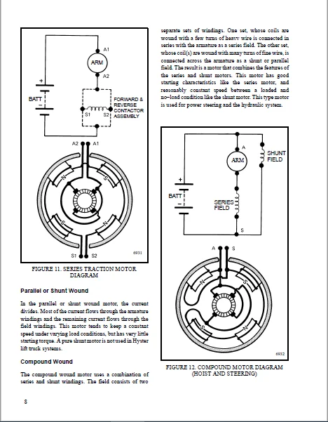
Series Wound..............................................................................................122
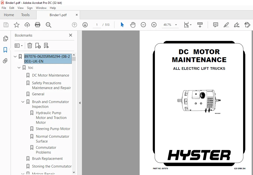
Parallel or Shunt Wound...................................................................................123
Compound Wound............................................................................................123
MOTOR INSULATION CLASS........................................................................................124
STORAGE.......................................................................................................124
HANDLING......................................................................................................124
BREAK–IN OPERATION............................................................................................124
CLEANING......................................................................................................125
BASIC REPAIR GUIDELINES.......................................................................................125
BEARINGS, SEALS AND LUBRICATION...............................................................................126
BRUSHES AND BRUSH HOLDERS.....................................................................................126
ARMATURE......................................................................................................127
COMMUTATOR....................................................................................................127
Description...............................................................................................127
SATISFACTORY SURFACE..........................................................................................128
STREAKING AND THREADING SURFACE...............................................................................129
GROOVING ON SURFACE...........................................................................................130
COPPER DRAG ON SURFACE........................................................................................132
OVERHEATING...................................................................................................132
FIELD ASSEMBLY................................................................................................134
INSPECTION CHECKLIST..........................................................................................134
CHECKING AND REPLACING MOTOR BRUSHES..........................................................................134
Inspecting Brushes........................................................................................134
INSPECT THE COMMUTATOR........................................................................................135
REPLACING BRUSHES.............................................................................................135
SEATING BRUSHES (STONING PROCEDURE)...........................................................................135
CHECK THE MOTORS FOR OPENS, GROUNDS AND SHORTS................................................................136
Check The Motor For Opens.................................................................................136
Check The Motor For Grounds...............................................................................136
Check The Motor For Shorts................................................................................136
COMMUTATOR INSPECTION.........................................................................................138
POLISHING COMMUTATOR..........................................................................................139
TURNING COMMUTATOR............................................................................................139
UNDERCUTTING COMMUTATOR.......................................................................................139
SLOT RAKING AND BRUSHING COMMUTATOR...........................................................................139
910102-2100SRM0103-(03-2005)-UK-EN....................................................................................141
toc...............................................................................................................141
Tilt Cylinders................................................................................................141
Safety Precautions Maintenance and Repair.....................................................................142
General.......................................................................................................145
Description...................................................................................................145
Tilt Cylinder Repair..........................................................................................145
Remove....................................................................................................145
Disassemble...............................................................................................145
Clean.....................................................................................................145
Assemble..................................................................................................146
Tilt Cylinders With O-Ring or Single-Lip Seals........................................................146
Tilt Cylinders for XM and XMS Models..................................................................147
Tilt Cylinders for XL, XLS, and XL 3 Models...........................................................148
Tilt Cylinders for H700-800A and Early Model H700-920B................................................150
Install...................................................................................................151
Tilt Cylinders Using Chevron Packing..................................................................151
Install...........................................................................................152
Tilt Cylinder Leak Check......................................................................................154
Tilt Cylinder Stroke and Mast Tilt Angle Adjustment...........................................................156
Torque Specifications.........................................................................................156
Piston Rod Nut............................................................................................156
Retainer..................................................................................................157
Troubleshooting...............................................................................................159
tables............................................................................................................141
Table 1. Movement Rates (Maximum) for Tilt Cylinders..........................................................155
910110-2200SRM0143-(08-2004)-UK-EN....................................................................................163
toc...............................................................................................................163
Instrument Panel Indicators and Senders.......................................................................163
Safety Precautions Maintenance and Repair.....................................................................164
General.......................................................................................................167
Description...................................................................................................168
Steering Column Gauges, Meters, and Indicators............................................................168
LED Display Panel.........................................................................................168
Battery Discharge Indicators..........................................................................168
Brush Wear Indicators.................................................................................175
Motor Temperature Indicators..........................................................................175
LX Series Display Panel...................................................................................177
Hourmeter Functions...................................................................................177
Battery Indicator Function............................................................................178
Status Code Function..................................................................................179
ZX Series Display Panels..................................................................................179
Display Panel.........................................................................................179
Basic Display Panels..................................................................................179
Performance Display...................................................................................182
Brush Wear Indicators.................................................................................185
Adjustments - General.........................................................................................186
Replacement - General Information.............................................................................186
Meter Replacement.............................................................................................187
Sender Replacement............................................................................................188
Fuel Level Sender.........................................................................................188
Pressure and Temperature Sender...........................................................................188
ITW Display Panel Replacement.................................................................................189
Remove....................................................................................................189
Column Mount Display Panel (EV-100/200ZX Motor Controllers) Repl..............................................190
Remove....................................................................................................190
Display Panel Assembly, Replace...........................................................................190
Indicator LEDs............................................................................................191
Battery Indicators........................................................................................191
Digital Display (Performance Display Panel Only)..........................................................191
Status Code or Performance Level Switches and Indicator LEDs (Pe..........................................191
Basic Display Panel, Replace Parts........................................................................191
Performance Display Panel, Replace Parts..................................................................193
Dash Mount Display Panel (EV100/200ZX Motor Controllers) Replace..............................................194
Remove and Replace........................................................................................194
Specifications................................................................................................194
Meter Specifications......................................................................................194
Sender Specifications.....................................................................................195
Troubleshooting...............................................................................................195
Meter.....................................................................................................195
910111-2200SRM0144-(05-1997)-UK-EN....................................................................................199
ELECTRICAL WARNING DEVICES........................................................................................199
GENERAL.......................................................................................................199
DESCRIPTION...................................................................................................199
Operator Controlled Horns.................................................................................199
System Warning Lights, Buzzers and Bells..................................................................199
Reverse Warning Horns.....................................................................................200
Warning Lights............................................................................................200
REPLACEMENT...................................................................................................201
General...................................................................................................201
Replacing Horns or Bells..................................................................................201
Replacing Horn Relay or Buzzer............................................................................201
Replacing Warning Lights..................................................................................201
Light Assemblies..........................................................................................202
Replacing Flashing Units..................................................................................202
910114-2260SRM0138-(06-2002)-UK-EN....................................................................................203
INTRODUCTION......................................................................................................203
GENERAL.......................................................................................................203
INDICATORS WITH METER MOVEMENTS...............................................................................204
BATTERY INDICATORS WITH LCD OR LED DISPLAYS...................................................................205
Liquid Crystal Displays...................................................................................205
Light Emitting Diode Displays.............................................................................206
CHECKS AND ADJUSTMENTS............................................................................................209
BATTERY INDICATORS WITHOUT LIFT INTERRUPT, EARYLY MODELS......................................................209
BATTERY INDICATORS WITH LIFT INTERRUPT, EARLY MODELS..........................................................210
Reset Potentiometer.......................................................................................210
Specific Gravity Alarm....................................................................................210
BATTERY INDICATORS WITHOUT LIFT INTERRUPT, LATER MODELS.......................................................210
BATTERY INDICATORS WITH LIFT INTERRUPT, LATER MODELS..........................................................210
Reset Potentiometer.......................................................................................211
Discharge Potentiometer...................................................................................211
LED DISPLAY WITH LIFT INTERRUPT...............................................................................211
CHECKING CURTIS 933-1 METER...................................................................................211
Reset Check ..............................................................................................212
Discharge Check...........................................................................................212
Lockout Check.............................................................................................213
Hour Glass Icon...........................................................................................213
ADJUSTMENT OF CURTIS 933-1 METER..............................................................................214
CHECKING CURTIS 1215 BATTERY INDICATOR........................................................................214
ADJUSTING CURTIS 1215 BATTERY INDICATOR.......................................................................215
Voltage Selection.........................................................................................216
REPAIRS...........................................................................................................217
BATTERY INDICATORS................................................................................................217
Replacement...................................................................................................217
CONTROLLER FOR THE BATTERY INDICATOR..............................................................................217
Replacement...................................................................................................217
DISPLAY PANEL COMPONENTS..........................................................................................217
910442-8000SRM0231-(12-2004)-UK-EN....................................................................................218
toc...............................................................................................................218
Metric and Inch (SAE) Fasteners...............................................................................218
Safety Precautions Maintenance and Repair.....................................................................219
General.......................................................................................................222
Threaded Fasteners........................................................................................222
Nomenclature, Threads.....................................................................................222
Strength Identification...................................................................................223
Cotter (Split) Pins.......................................................................................223
Fastener Torque Tables....................................................................................228
Conversion Table..........................................................................................230
tables............................................................................................................218
Table 1. Bolts and Screws.....................................................................................224
Table 2. Studs and Nuts.......................................................................................225
Table 3. Torque Nuts..........................................................................................226
Table 4. Torque Nuts With Nylon Insert........................................................................227
Table 5. Torque Values for Metric Fasteners*..................................................................228
Table 6. Torque Values for Inch Fasteners*....................................................................229
Table 7. Conversion Table for Metric and English Units........................................................230
Table 8. Cotter Pin Dimensional Data..........................................................................231
Table 9. Cotter Pin Dimensional Data..........................................................................232
Table 10. Cotter Pin Dimensional Data.........................................................................233
Table 11. Cotter Pin Dimensional Data.........................................................................235
1482603-0100SRM0793-(03-2000)-UK-EN...................................................................................240
toc...............................................................................................................240
Frame.........................................................................................................240
Safety Precautions Maintenance and Repair.....................................................................241
General.......................................................................................................244
Description...................................................................................................244
Overhead Guard Repair.........................................................................................245
Remove....................................................................................................245
Install...................................................................................................245
Hood and Seat Assembly Repair.................................................................................245
Remove....................................................................................................247
Install...................................................................................................247
Counterweight Repair..........................................................................................247
Remove....................................................................................................247
Install...................................................................................................248
Hydraulic Tank Repair.........................................................................................249
Inspect...................................................................................................249
Small Leaks, Repair.......................................................................................249
Large Leaks, Repair.......................................................................................249
Clean.....................................................................................................249
Steam Method..........................................................................................249
Chemical Solution Method..............................................................................250
Additional Preparations for Repair........................................................................250
Safety Labels.................................................................................................250
Battery Specifications........................................................................................253
tables............................................................................................................240
Table 1. Weight of Counterweights.............................................................................248
1482607-0630SRM0794-(05-2000)-UK-EN...................................................................................256
toc...............................................................................................................256
Master Drive Unit (ZF)........................................................................................256
Safety Precautions Maintenance and Repair.....................................................................257
General.......................................................................................................260
Description...................................................................................................260
Top Section Housing.......................................................................................260
Transmission Housing......................................................................................260
Repair........................................................................................................261
Remove....................................................................................................261
Disassemble...............................................................................................262
Top Section Housing...................................................................................262
Transmission Housing..................................................................................265
Assemble..................................................................................................267
Installing Spiral Bevel Pinion Shaft..................................................................267
Measuring Bearing Movement in Bevel Pinion Shaft......................................................269
Assembly of Helical Gear..............................................................................270
Assembling Crown Gear and Wheel Shaft.................................................................270
Assembling Transmission Housing Cover.................................................................272
Assembling Input Motor Pinion Gear....................................................................272
Inspecting Top Section Housing........................................................................272
Measuring Pivoting Bearing Movement...................................................................273
Installing Top Section Housing........................................................................273
Install...................................................................................................274
Tooth Contact Pattern Adjustment..............................................................................275
Changing Transmission Oil.....................................................................................276
Troubleshooting...............................................................................................277
tables............................................................................................................256
Table 1. Tooth Contact Pattern................................................................................275
1482613-0630SRM0795-(04-2000)-UK-EN...................................................................................282
toc...............................................................................................................282
Master Drive Unit (Kordel)....................................................................................282
Safety Precautions Maintenance and Repair.....................................................................283
General.......................................................................................................286
Description...................................................................................................286
Upper Section.............................................................................................286
Lower Section.............................................................................................288
Drive Unit Repair.............................................................................................288
Remove....................................................................................................288
Disassemble...............................................................................................289
Assemble..................................................................................................292
General...............................................................................................292
Assemble Component Subassemblies......................................................................292
Assemble Components Into Lower Section................................................................292
Assemble Upper and Lower Sections.....................................................................293
Install...................................................................................................293
Check and Change Transmission Oil.............................................................................294
Tooth Contact Pattern Adjustment..............................................................................295
Troubleshooting...............................................................................................296
tables............................................................................................................282
Table 1. Tooth Contact Pattern................................................................................295
1482617-1600SRM0797-(03-2000)-UK-EN...................................................................................300
toc...............................................................................................................300
Steering Control Unit.........................................................................................300
Safety Precautions Maintenance and Repair.....................................................................301
General.......................................................................................................304
Description...................................................................................................304
Operation.....................................................................................................304
Steering Wheel and Column Assembly Repair.....................................................................306
Steering Column Assembly Repair...............................................................................307
Remove and Disassemble....................................................................................307
Assemble and Install......................................................................................307
Steering Control Unit, Disassemble........................................................................308
Steering Control Unit, Clean..............................................................................310
Steering Control Unit, Assemble...........................................................................311
System Air Removal............................................................................................314
Troubleshooting...............................................................................................315
1482620-1600SRM0796-(03-2000)-UK-EN...................................................................................320
toc...............................................................................................................320
Steering System...............................................................................................320
Safety Precautions Maintenance and Repair.....................................................................321
General.......................................................................................................324
Description...................................................................................................324
Steering Wheel and Column Assembly........................................................................325
Steering Control Unit Repair..................................................................................329
Remove....................................................................................................329
Install...................................................................................................329
Hydraulic Steering Motor Repair...............................................................................330
Description...............................................................................................330
Remove....................................................................................................330
Disassemble...............................................................................................330
Clean and Inspect.........................................................................................332
Assemble..................................................................................................332
Install...................................................................................................333
Direction Control Lever Repair................................................................................333
Remove....................................................................................................333
Assemble..................................................................................................334
Install...................................................................................................334
Power Steering Adjustments....................................................................................334
Air in Steering System....................................................................................334
Steering Pressure.........................................................................................334
Steering Chain, Adjust....................................................................................335
Troubleshooting...............................................................................................335
1482623-1800SRM0803-(03-2000)-UK-EN...................................................................................340
toc...............................................................................................................340
Brake System..................................................................................................340
Safety Precautions Maintenance and Repair.....................................................................341
General.......................................................................................................344
Description and Operation.....................................................................................344
Master Cylinder Repair........................................................................................346
Remove and Disassemble....................................................................................346
Clean and Inspect.........................................................................................347
Assemble and Install......................................................................................347
Service and Parking Brakes Repair.............................................................................348
Remove and Disassemble....................................................................................348
Clean.....................................................................................................349
Inspect...................................................................................................349
Assemble and Install......................................................................................350
Brake System Air Removal......................................................................................350
Service Brakes Adjustment.....................................................................................351
Brake Pedal Adjustment........................................................................................351
Parking Brake Adjustment......................................................................................352
Troubleshooting...............................................................................................352
1482626-1900SRM0802-(04-2000)-UK-EN...................................................................................358
toc...............................................................................................................358
Hydraulic System..............................................................................................358
Safety Precautions Maintenance and Repair.....................................................................359
General.......................................................................................................362
Description...................................................................................................362
Control Valve Repair..........................................................................................364
Description...............................................................................................364
Operation.................................................................................................364
Lift..................................................................................................364
Tilt and Auxiliary....................................................................................364
Relief Valve..........................................................................................368
Check Valves..........................................................................................368
Description.......................................................................................368
Clean and Inspect.................................................................................368
Repairs...................................................................................................368
Remove................................................................................................368
Disassemble...........................................................................................369
Relief Valve Repair...................................................................................369
Clean and Inspect.....................................................................................370
Assemble..............................................................................................370
Install...............................................................................................370
Checks....................................................................................................370
Relief Valve Check....................................................................................370
Adjust....................................................................................................371
Relief Valve..........................................................................................371
Control Levers, Linkage and Switches..................................................................371
Hydraulic Pump Repair.........................................................................................373
Description...............................................................................................373
Repairs...................................................................................................373
Remove................................................................................................373
Seal, Replace.........................................................................................374
Install...............................................................................................375
Specifications................................................................................................377
Relief Valves Pressures...................................................................................377
Hydraulic System Capacity.................................................................................377
Troubleshooting...............................................................................................377
Hydraulic Pump............................................................................................377
Control Valve.............................................................................................378
1482629-2200SRM0806-(10-2001)-UK-EN...................................................................................384
toc...............................................................................................................384
Sevcon® SC2126 Motor Controller...............................................................................384
Safety Precautions Maintenance and Repair.....................................................................385
General.......................................................................................................388
Lift Truck Control........................................................................................388
Plugging..................................................................................................389
Contactors................................................................................................389
Circuit Protection........................................................................................390
Current Limit.........................................................................................390
Fuses.................................................................................................390
Controller Operation..........................................................................................391
General Operation.........................................................................................391
Operating Frequency...................................................................................391
Temperature Monitoring................................................................................391
Safe Operating Area (SOA).............................................................................391
Undervoltage and Overvoltage Protection...............................................................391
Diagnostic LED........................................................................................392
Fault Clearance.......................................................................................392
Software Version and Revision Indication..............................................................392
Setup Menu............................................................................................392
Multi Languages.......................................................................................392
Power Circuit Descriptions....................................................................................392
Traction Operation........................................................................................393
Start Up Sequence.....................................................................................393
Static Return to Off (SRO)............................................................................393
Seat Switch...........................................................................................393
Acceleration Delay....................................................................................393
Deceleration Delay....................................................................................393
Creep.................................................................................................393
Regenerative Braking..................................................................................393
Plug Braking..........................................................................................394
Brake Constant Factor.................................................................................394
Antirollback..........................................................................................394
Analog Inputs.........................................................................................394
Traction Accelerator..................................................................................394
Digital Switch Inputs.................................................................................394
Contactors............................................................................................395
Contactor Chopping....................................................................................395
Fail-Safe.............................................................................................395
Pump Operation............................................................................................395
Pump Speeds and Priorities............................................................................396
Additive Speeds.......................................................................................396
Power Steer Speed.....................................................................................396
Pump Inhibit Input....................................................................................396
Pump Speed Compensation...............................................................................396
Calibration and Adjustments...................................................................................397
Traction Personalities (Controller Adjustments)...........................................................397
Traction Status Information...............................................................................399
Traction Test Information.................................................................................399
BDI Adjustments...........................................................................................400
Fault Log.................................................................................................400
Setup Menu (Enables/Disables Features)....................................................................400
Pump Personalities (Controller Adjustments)...............................................................400
Pump Status Information...................................................................................401
Pump Test Information.....................................................................................402
Pump Setup Menu...........................................................................................402
Traction and Pump Adjustment Descriptions.................................................................402
Setup Menu Descriptions...................................................................................404
Controller Connections........................................................................................405
Power Connections.........................................................................................405
Controller Connections................................................................................405
Contactor Connections.................................................................................405
Contactor Types.......................................................................................405
Fuse Ratings..........................................................................................405
Back Panel Connectors.....................................................................................405
Connector A - 24 Pin..................................................................................406
Connector B - 12 Pin..................................................................................406
Connector C - 6 Pin...................................................................................407
Controller Area Network (CAN) Overview....................................................................407
Diagnostics...................................................................................................407
Service and Fault Logs........................................................................................409
Service Log...............................................................................................409
Fault Log.................................................................................................409
Technical Specifications......................................................................................410
Environmental.............................................................................................410
Mechanical................................................................................................410
Electrical................................................................................................410
Voltage Specifications:...............................................................................410
Current Specifications:...............................................................................411
Miscellaneous Controller Specifications:..............................................................411
Contactor Repair..............................................................................................412
General...................................................................................................414
Remove Contactor Assembly.................................................................................414
Contactor Contacts........................................................................................414
Coil......................................................................................................414
Control Switches..............................................................................................416
Key Switch................................................................................................416
Seat Switch...............................................................................................416
Start Switch..............................................................................................416
Brake Pedal Adjustment........................................................................................416
Accelerator Pedal Adjustment..................................................................................417
tables............................................................................................................384
Table 1. Over- and Undervoltage Protection....................................................................391
1482632-8000SRM0798-(03-2000)-UK-EN...................................................................................420
toc...............................................................................................................420
Periodic Maintenance..........................................................................................420
Safety Precautions Maintenance and Repair.....................................................................421
General.......................................................................................................424
How to Move Disabled Lift Truck...........................................................................424
How to Tow Lift Truck.................................................................................424
How to Put Lift Truck on Blocks...........................................................................425
How to Raise Load Wheels..............................................................................425
How to Raise Steer Wheels.............................................................................426
Safety Procedures When Working Near Mast......................................................................426
Maintenance Schedule..........................................................................................428
Maintenance Procedures Every 8 Hours or Daily.................................................................430
Checks Before Operation...................................................................................430
Hydraulic System......................................................................................430
Battery...............................................................................................431
Battery Restraint System..............................................................................431
Operator Restraint System.............................................................................432
Mast, Forks, and Lift Chains..........................................................................432
Lift Chain Adjustments................................................................................434
Tires and Wheels......................................................................................434
Check Operation...........................................................................................435
Gauges and Horn.......................................................................................435
Control Levers and Pedals.............................................................................435
Lift System Operation.................................................................................435
Service Brakes........................................................................................436
Parking Brake.........................................................................................436
Steering System.......................................................................................436
Maintenance Procedures Every 500 Hours or 2 Months............................................................436
Hydraulic Tank Breather...................................................................................436
Wheel Nut Torques.........................................................................................436
Master Drive Unit (MDU)...................................................................................436
Mast......................................................................................................437
Lift Chains...............................................................................................437
Forks.....................................................................................................438
Safety Labels.............................................................................................438
Brake Fluid...............................................................................................438
Other Lubrication.........................................................................................438
Electrical Inspection.....................................................................................439
Contactors............................................................................................439
Motor Brushes.........................................................................................439
Maintenance Procedures Every 2000 Hours or Yearly.............................................................440
Hydraulic System..........................................................................................440
Change Hydraulic Oil Filter...........................................................................440
Change Hydraulic Oil..................................................................................440
Brake Shoes...............................................................................................440
Steering System...........................................................................................440
Master Drive Unit.........................................................................................440
Adjust Service Brakes.....................................................................................441
Adjust Parking Brake......................................................................................441
Lift and Tilt System Leak Check...............................................................................442
Lift System...............................................................................................442
Tilt System...............................................................................................443
Battery Maintenance...........................................................................................443
How to Charge Battery.....................................................................................443
How to Change Battery.....................................................................................444
Battery Size Specifications...............................................................................445
Wheel and Tire Maintenance....................................................................................446
General...................................................................................................446
How to Change Tires.......................................................................................446
Solid Rubber Tires on Pneumatic Wheels....................................................................446
Remove Wheels From Lift Truck.........................................................................446
Remove Solid Rubber Tire From Pneumatic Wheel.........................................................447
Install Solid Rubber Tire on Pneumatic Wheel..........................................................448
Wheels, Install.......................................................................................449
tables............................................................................................................420
Table 1. Maintenance Schedule.................................................................................429
Table 2. Battery Size Specifications - Type: Lead-Acid Battery................................................445
1482635-8000SRM0804-(04-2000)-UK-EN...................................................................................452
toc...............................................................................................................452
Capacities and Specifications.................................................................................452
Safety Precautions Maintenance and Repair.....................................................................453
Wheels and Tires..............................................................................................456
Hydraulic System..............................................................................................456
Motors (24 Volt)..............................................................................................456
Mast Creep Speeds.............................................................................................456
Mast Speeds...................................................................................................457
Battery Size Specifications...................................................................................458
Torque Specifications.........................................................................................458
Frame.....................................................................................................458
Master Drive Unit (MDU) (ZF Gotha)........................................................................458
Master Drive Unit (MDU) (Kordel)..........................................................................458
Steering System...........................................................................................458
Brake System..............................................................................................459
Hydraulic System..........................................................................................459
Mast......................................................................................................459
Wheels....................................................................................................459
Sevcon SC2126 Motor Controller Adjustments....................................................................459
1515047-2200SRM1014-(11-2001)-UK-EN...................................................................................462
toc...............................................................................................................462
Sevcon Traction and Pump Controllers..........................................................................462
Safety Precautions Maintenance and Repair.....................................................................463
Sevcon PCpak..................................................................................................468
Introduction..............................................................................................468
System Requirements.......................................................................................468
Traction Controller Safety....................................................................................468
Traction Controller Introduction..............................................................................469
Traction Controller Installation..............................................................................469
Mounting..................................................................................................469
Traction Controller Calibration...............................................................................471
Adjustments...............................................................................................471
Status and Test Information...............................................................................472
Traction Controller Configuration.............................................................................473
System Configuration......................................................................................473
System Voltage............................................................................................473
System I/O Configuration..................................................................................473
System/Motor Setup........................................................................................475
Armature Field Map........................................................................................475
Armature and Field Current Limit..........................................................................476
Contactor Chopping........................................................................................477
Accelerator Full/Zero Setting.............................................................................477
Performance...............................................................................................477
Acceleration Delay........................................................................................477
Deceleration Delay........................................................................................477
Control Mode..............................................................................................478
Plugging..................................................................................................478
Types of Braking..........................................................................................478
Braking Levels............................................................................................478
Footbraking...............................................................................................478
Footbrake Pot.............................................................................................479
Footbrake Priority........................................................................................480
Creep Speed...............................................................................................480
Maximum Speed.............................................................................................480
Traction Controller Commissioning.............................................................................480
Checklist.................................................................................................480
Traction Controller Features..................................................................................482
Accelerator Characteristics...............................................................................482
Features..................................................................................................483
Standard Controller Features..............................................................................483
Power Steer...............................................................................................483
High Speed Switch and Anti-Tie Down.......................................................................484
Seat Switch...............................................................................................485
Traction Drive Hours Meter................................................................................485
Personality Checksum......................................................................................485
Reverse Buzzer............................................................................................485
Traction Controller Safety Features...........................................................................485
Start Up Sequence.........................................................................................485
SRO (Static Return to Off)................................................................................485
Belly Switch (not used)...................................................................................486
Anti-Rollback.............................................................................................486
Anti-Rolloff..............................................................................................486
Fail-Safe.................................................................................................486
Traction Controller Protection................................................................................486
Controller Protection Features............................................................................486
Temperature Monitoring....................................................................................486
Maximum Temperature Logging...............................................................................487
Timed Current Cutback.....................................................................................487
Safe Operating Area (SOA).................................................................................488
Under-Voltage and Over-Voltage Protection.................................................................489
Traction Controller Diagnostics...............................................................................490
Fault Codes...............................................................................................490
Fault Code Clearance......................................................................................491
Software Version and Serial Number Indication.............................................................491
Traction Controller Specifications............................................................................492
Power Configurations......................................................................................492
EMC Standards.............................................................................................492
Socket B Protection.......................................................................................492
Contactor Drive Ratings...................................................................................492
Analogue Input Impedance..................................................................................492
Digital Input Impedance...................................................................................492
EMC Guidelines............................................................................................492
Power Cables..............................................................................................493
Signal Cables.............................................................................................493
Controller................................................................................................493
Pump Controller Safety........................................................................................493
Pump Controller Introduction..................................................................................493
Pump Controller Installation..................................................................................494
Mounting..................................................................................................494
MillipaK Pump Power Wiring................................................................................494
Pump Controller Calibration...................................................................................495
Adjustments...............................................................................................495
Status and Test Information...............................................................................496
Pump Controller Configuration.................................................................................497
System Configuration......................................................................................497
System Voltage............................................................................................497
System I/O Configuration..................................................................................497
Current Limit.............................................................................................498
Accelerator Full/Zero Setting.............................................................................498
Performance...............................................................................................499
Lift and Power Steer Ramps................................................................................499
Creep Speed...............................................................................................499
Maximum Speed.............................................................................................499
Pump Controller Commissioning.................................................................................500
Under-Voltage Protection..................................................................................500
Commissioning Checklist...................................................................................500
Personalities Record......................................................................................501
Pump Controller Features......................................................................................502
Features..................................................................................................502
Standard Controller Features..............................................................................502
Lift Switch Inputs - Priority.............................................................................502
Lift Switch Inputs - Additive.............................................................................503
Compensation..............................................................................................503
Power Steer Input.........................................................................................503
Lift Inhibit Input........................................................................................504
Cooling Fan...............................................................................................504
Pump Hours Meter..........................................................................................504
Personality Checksum......................................................................................504
Pump Controller Safety Features...............................................................................504
Fail-safe.................................................................................................504
Pump Controller Protection....................................................................................504
Controller Protection Features............................................................................504
Temperature Monitoring....................................................................................504
Maximum Temperature Logging...............................................................................505
Timed Current Cutback.....................................................................................505
Safe Operating Area (SOA).................................................................................506
Pump Controller Diagnostics...................................................................................506
Diagnostics...............................................................................................506
Fault Clearance...........................................................................................507
Using Status and Test Menus...............................................................................507
Software Version and Serial Number Indication.............................................................508
Pump Controller Specifications................................................................................509
Power Configurations......................................................................................509
EMC Standards.............................................................................................509
Socket B Protection.......................................................................................509
Contactor Drive Ratings...................................................................................509
Analogue Input Impedance..................................................................................509
Digital Input Impedance...................................................................................509
Ordering Information..........................................................................................510
EMC Guidelines............................................................................................510
Power Cables..............................................................................................510
Signal Cables.............................................................................................510
Controller................................................................................................510
tables............................................................................................................462
Table 1. Adjustment Menus.....................................................................................471
Table 2. Status and Test Information Menus....................................................................472
Table 3. Description of each Digital I/O Configuration........................................................473
Table 4. Digital Functions....................................................................................474
Table 5. Pin Allocations......................................................................................475
Table 6. Analogue Functions...................................................................................475
Table 7. Personality Record...................................................................................480
Table 8. Internal Power Steer Triggers........................................................................483
Table 9. Timed Current Limit Cutback Levels...................................................................487
Table 10. Under- and Over-Voltage Cutback Levels..............................................................489
Table 11. Flash Fault Descriptions............................................................................490
Table 12. Fault Codes and Descriptions........................................................................490
Table 13. Software Version Format.............................................................................491
Table 14. Serial Number Format................................................................................492
Table 15. Power Configurations................................................................................492
Table 16. Analogue Function...................................................................................498
Table 17. Personality Record..................................................................................501
HYSTER C203 SERVICE MANUAL – PDF DOWNLOAD:
IMAGES PREVIEW OF THE MANUAL:
PLEASE NOTE:
- This is the same manual used by the dealers to diagnose and troubleshoot your vehicle
- You will be directed to the download page as soon as the purchase is completed. The whole payment and downloading process will take anywhere between 2-5 minutes
- Need any other service / repair / parts manual, please feel free to contact [email protected] . We still have 50,000 manuals unlisted
S.V