Trusted Business
Verified & Licensed
Virus Free Files
100% Safe Downloads
Secure Payment
SSL Protected
Instant Delivery
Available Immediately
Sale!


Hyster E30 50B, E60BS, E60 120B service manual – PDF DOWNLOAD
Original price was: $92.95.$32.95Current price is: $32.95.
Hyster E30 50B, E60BS, E60 120B service manual
Instant PDF Download
Available immediately
Save to Your Device
Download & keep forever
Antivirus Scanned
100% virus-free
Trusted Worldwide
175,000+ customers
Description
Hyster E30 50B, E60BS, E60 120B service manual
File Details:
Hyster E30 50B, E60BS, E60 120B service manual
Language : English
Pages : 396
Size : 10.1 MB
Downloadable : Yes
Format : PDF
HYSTER E30 50B, E60BS, E60 120B SERVICE MANUAL – PDF DOWNLOAD:
Image Preview:
Description:
Hyster E30 50B, E60BS, E60 120B service manual
- From dock to stock and anywhere in between, the Hyster® E30-40HSD3 series is your versatile materials handling workhorse. Engineered with superior ergonomics, these 3,000 to 4,000-pound capacity three-wheel stand-up lift trucks are easy to operate and easily demonstrate that increased operator comfort helps to improve productivity. MORE ACTION, LESS RE-ACTION Work can be hard. And gritty. But maneuvering and maintaining your materials handling equipment shouldn’t be.
- You need a lift truck that consistently and efficiently maneuvers in and around tight spaces and, at the end of the shift, one that is easily cleaned and maintained. Shouldn’t your lift truck be as tough as the warehouse it works in? The Hyster® E30-40HSD3 three-wheel stand lift truck has a small turning radius — turning in smaller aisles and dock operations than a sit-down unit. Your operators can save valuable time and be more productive when using one forklift that can handle the big and small spaces. When a job gets dirty, so does your forklift. But that’s no challenge for this forklift. With sealed electrical connectors as well as enclosed master drive units and motors, you know that harmful dirt and grime will stay out of the components and washing down this forklift will be worry-free. The AC traction and hoist motors eliminate the need for commutating brushes, and can reduce maintenance requirements.
- Cooler/freezer options are available for extreme environments. A tough forklift comes with a great warranty: 12 month/unlimited hours full forklift limited warranty 36 month/6,000 hour powertrain limited warranty Lifetime frame warranty (Offered to the original owner only. Contact your Hyster® dealer for full details.) STAND UP FOR THE RIGHT TO BE COMFORTABLE Your operators can spend a lot of time getting in and out of a sit-down lift truck to pick and move product. Wouldn’t it make sense to eliminate some of that effort and make it easier for them to do their jobs? Are your operators sitting on the job when they should be standing? The E30-40HSD3 three-wheel stand forklift is an operator’s dream
- . Easy on/off access, low step height and a spacious suspended floor help to alleviate fatigue and can increase productivity. Your operators will be in control with fully proportional travel, lift/lower, tilt, and sideshift functions. With more usable floor area than leading competitors, and no pedals to stand on to enable travel, your operators can adjust posture freely.
Table of Contents:
Hyster E30 50B, E60BS, E60 120B service manual
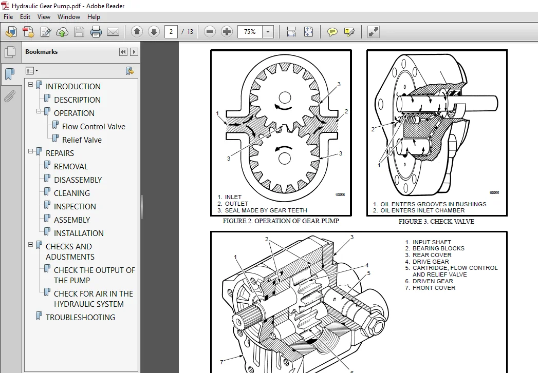
INTRODUCTION................................................................................................................................  1
	GENERAL.................................................................................................................................  1
	INDICATORS WITH METER MOVEMENTS.........................................................................................................  2
	BATTERY INDICATORS WITH LCD OR LED DISPLAYS.............................................................................................  3
		Liquid Crystal Displays.............................................................................................................  3
		Light Emitting Diode Displays.......................................................................................................  7
CHECKS AND ADJUSTMENTS......................................................................................................................  9
	BATTERY INDICATORS WITHOUT LIFT INTERRUPT, EARLY MODELS.................................................................................  9
	BATTERY INDICATORS WITH LIFT INTERRUPT, EARLY MODELS....................................................................................  9
		Reset Potentiometer.................................................................................................................  9
		Specific Gravity Alarm.............................................................................................................. 10
	BATTERY INDICATORS WITHOUT LIFT INTERRUPT, LATER MODELS................................................................................. 11
	BATTERY INDICATORS WITH LIFT INTERRUPT, EARLY MODELS.................................................................................... 11
		Reset Potentiometer................................................................................................................. 11
		Discharge Potentiometer............................................................................................................. 11
	LED DISPLAY WITH LIFT INTERRUPT......................................................................................................... 12
	CHECKING CURTIS 933-1 METER............................................................................................................. 12
		Reset Check......................................................................................................................... 12
		Discharge Check..................................................................................................................... 13
		Lockout Check....................................................................................................................... 13
		LED's Do Not Illuminate............................................................................................................. 14
		Hourmeter Check..................................................................................................................... 14
		Hour Glass Icon..................................................................................................................... 14
		ADJUSTMENT OF CURTIS 933-1 METER.................................................................................................... 14
		CHECKING CURTIS 1215 BATTERY INDICATOR.............................................................................................. 14
		ADJUSTING CURTIS 1215 BATTERY INDICATOR............................................................................................. 15
			Voltage Selection............................................................................................................... 16
		ADJUSTING BDI OF SEM DISPLAY PANEL.................................................................................................. 17
	REPAIRS................................................................................................................................. 17
		BATTERY INDICATORS.................................................................................................................. 17
			Replacement..................................................................................................................... 17
		CONTROLLER FOR THE BATTERY INDICATOR................................................................................................ 17
			Replacement..................................................................................................................... 17
		DISPLAY PANEL COMPONENTS............................................................................................................ 17
		REPLACING SEM DISPLAY PANEL......................................................................................................... 17
		SEM Display Panel REMOVAL........................................................................................................... 19
			Removal And Replacement......................................................................................................... 19
INTRODCUTION................................................................................................................................ 21
	General................................................................................................................................. 21
	Description and Operation............................................................................................................... 21
REPAIRS..................................................................................................................................... 22
	Removal and Disassembly................................................................................................................. 23
	Cleaning................................................................................................................................ 23
	Inspection.............................................................................................................................. 24
	Assembly and Installation............................................................................................................... 24
CHECKS AND ADJUSTMENTS...................................................................................................................... 26
	Manual Adjustment for the Service Brakes................................................................................................ 26
	Removing the Air from the Brake System.................................................................................................. 27
TROUBLESHOOTING............................................................................................................................. 29
INTRODUCTION................................................................................................................................ 38
MAGNETISM................................................................................................................................... 38
	MAGNETISM AND PERMANENT MAGNETS......................................................................................................... 38
	ELECTROMAGNETIC FIELDS.................................................................................................................. 38
	ELECTROMAGNETS.......................................................................................................................... 39
	ELECTROMAGNETIC INDUCTION............................................................................................................... 40
	MAGNETIC FORCE ON A CONDUCTOR........................................................................................................... 40
BASIC MOTORS................................................................................................................................ 41
	MOTOR OPERATION......................................................................................................................... 41
	COMMUTATION PRINCIPLE................................................................................................................... 42
	DIRECTION OF MOTOR ROTATION............................................................................................................. 42
	MOTOR SPEED............................................................................................................................. 42
	MOTOR TORQUE............................................................................................................................ 43
	COUNTER ELECTROMOTIVE FORCE............................................................................................................. 43
	TYPICAL MOTOR........................................................................................................................... 43
	TYPES OF MOTORS......................................................................................................................... 43
		Permanent–Magnet.................................................................................................................... 43
		Series Wound........................................................................................................................ 44
		Parallel or Shunt Wound............................................................................................................. 45
		Compound Wound...................................................................................................................... 45
	MOTOR INSULATION CLASS.................................................................................................................. 46
	STORAGE................................................................................................................................. 46
	HANDLING................................................................................................................................ 46
	BREAK–IN OPERATION...................................................................................................................... 46
	CLEANING................................................................................................................................ 47
	BASIC REPAIR GUIDELINES................................................................................................................. 47
	BEARINGS, SEALS AND LUBRICATION......................................................................................................... 48
	BRUSHES AND BRUSH HOLDERS............................................................................................................... 48
	ARMATURE................................................................................................................................ 49
	COMMUTATOR.............................................................................................................................. 49
		Description......................................................................................................................... 49
	SATISFACTORY SURFACE.................................................................................................................... 50
	STREAKING AND THREADING SURFACE......................................................................................................... 51
	GROOVING ON SURFACE..................................................................................................................... 52
	COPPER DRAG ON SURFACE.................................................................................................................. 54
	OVERHEATING............................................................................................................................. 54
	FIELD ASSEMBLY.......................................................................................................................... 56
	INSPECTION CHECKLIST.................................................................................................................... 56
	CHECKING AND REPLACING MOTOR BRUSHES.................................................................................................... 56
		Inspecting Brushes.................................................................................................................. 56
	INSPECT THE COMMUTATOR.................................................................................................................. 57
	REPLACING BRUSHES....................................................................................................................... 57
	SEATING BRUSHES (STONING PROCEDURE)..................................................................................................... 57
	CHECK THE MOTORS FOR OPENS, GROUNDS AND SHORTS.......................................................................................... 58
		Check The Motor For Opens........................................................................................................... 58
		Check The Motor For Grounds......................................................................................................... 58
		Check The Motor For Shorts.......................................................................................................... 58
	COMMUTATOR INSPECTION................................................................................................................... 60
	POLISHING COMMUTATOR.................................................................................................................... 61
	TURNING COMMUTATOR...................................................................................................................... 61
	UNDERCUTTING COMMUTATOR................................................................................................................. 61
	SLOT RAKING AND BRUSHING COMMUTATOR..................................................................................................... 61
ELECTRICAL SYSTEM CABLING DIAGRAM........................................................................................................... 63
ELECTRICAL SYSTEM SCHEMATIC DIAGRAM 36/48 VOLT*............................................................................................. 64
ELECTRICAL SYSTEM WIRING DIAGRAM 36/48 VOLT*................................................................................................ 66
ELECTRICAL SYSTEM SCHEMATIC DIAGRAM 72/80 VOLT*............................................................................................. 68
ELECTRICAL SYSTEM WIRING DIAGRAM 72/80 VOLT*................................................................................................ 70
SCHEMATIC DIAGRAM WITH ACCELERATOR BOX 36/48 VOLT........................................................................................... 72
WIRING DIAGRAM WITH ACCELERATOR BOX 36/48 VOLT.............................................................................................. 74
SCHEMATIC DIAGRAM WITH ACCELERATOR BOX 72/80 VOLT........................................................................................... 76
WIRING DIAGRAM WITH ACCELERATOR BOX 72/80 VOLT.............................................................................................. 78
LIFT/TILT HYDRAULIC SYSTEM SCHEMATIC........................................................................................................ 80
FIGURE 1. SCHEMATIC DIAGRAM WITH ACCELERATOR CARD........................................................................................... 82
FIGURE 2. SCHEMATIC DIAGRAM WITH ACCELERATOR CARD AND SEAT BRAKE............................................................................ 84
FIGURE 3. WIRING DIAGRAM WITH ACCELERATOR CARD.............................................................................................. 86
FIGURE 4. WIRING DIAGRAM, 36/48 VOLT EV-1 CONTROL .......................................................................................... 88
FIGURE 5. SCHEMATIC DIAGRAM, 36/48 VOLT EV-1 CONTROL........................................................................................ 90
FIGURE 6. WIRING DIAGRAM, 72/80 VOLT EV-1 CONTROL........................................................................................... 92
FIGURE 7. SCHEMATIC DIAGRAM 72/80 VOLT EV-1 CONTROL......................................................................................... 94
FIGURE 8. SCHEMATIC DIAGRAM, 36/48 VOLT EV-1W CONTROL ...................................................................................... 96
FIGURE 9. WIRING DIAGRAM, 36/48 VOLT EV-1W CONTROL ......................................................................................... 98
FIGURE 10. SCHEMATIC DIAGRAM, 72/80 VOLT EV-1W CONTROL......................................................................................100
FIGURE 11. WIRING DIAGRAM, 72/80 VOLT EV-1W CONTROL ........................................................................................102
INTRODUCTION................................................................................................................................103
	General.................................................................................................................................103
	Description.............................................................................................................................103
REPAIRS.....................................................................................................................................104
	Removal.................................................................................................................................104
	Installation............................................................................................................................105
	Axle Housing For S30-100E And S40-50F Lift Trucks.......................................................................................106
	Wheels And Tires........................................................................................................................108
TROUBLESHOOTING.............................................................................................................................110
SPECIFICATIONS..............................................................................................................................111
ELECTRICAL CHECKS AND ADJUSTMENTS FOR SitDrive) ELECTRICAL LIFT TRUCKS......................................................................113
	GENERAL.................................................................................................................................113
	CONTROL AND POWER FUSES.................................................................................................................118
	CONTROL CARD ADJUSTMENTS................................................................................................................119
		Adjusting Creep Speed, "CREEP'......................................................................................................121
		Adjusting Controlled Acceleration, "C/A" ...........................................................................................121
		Adjusting Current Limit, "C/L"......................................................................................................122
		Adjust "1A TIME"....................................................................................................................123
		Adjust 1A Drop Out, "1A D.O"........................................................................................................125
		Adjust Plugging, "PLUG".............................................................................................................125
		Ramp Start..........................................................................................................................125
		Adjust Field Weakening Pick Up and Drop Out, "F.W.P.U." And "F.W.D.O."..............................................................125
		Adjust "REGEN C/L" (Current Limit)..................................................................................................126
		Adjust "REGEN D.O." (Drop Out)......................................................................................................126
	PROPORTIONAL CONTROL (J25-35A Only).....................................................................................................129
	SCR CONTROL, DUAL HYDRAULIC PUMP MOTORS.................................................................................................130
	SCR CONTROL, SINGLE PUMP MOTOR..........................................................................................................130
		Accelerator Card (E-20-100B, J40-60AS Only).........................................................................................131
		Circuit Description For Accelerator Card Used With A Seat Switch....................................................................132
		Accelerator "START" (IC3)...........................................................................................................133
		Accelertor "1A TIME" (IC2)..........................................................................................................133
		Circuit Description For Accelerator Card Used With A Seat Brake.....................................................................133
		Accelerator "START" (IC3)...........................................................................................................134
		Accelerator "1A TIME" (IC1 and IC2).................................................................................................134
		CHECK THE ACCELERTOR CARD...........................................................................................................134
		ADJUSTING THE ACCELERATOR CARD......................................................................................................134
	THE POTENTIOMETERS AND CONTOL SWITCHES..................................................................................................134
		Steering Potentiometer (J25-35A Only)...............................................................................................134
		Accelerator Potentiometer And Start Switch (E20-120XL And J25-60XL Only)............................................................136
		Accelerator Potentiometer And Direction Switch......................................................................................137
		Adjusting Start Switch..............................................................................................................138
		"FORWARD" And "REVERSE" Switch (MONOTROL) (Earlier Production Lift Trucks)..........................................................138
		Direction Switches (MONOTROL) (Later Production Lift Trucks)........................................................................139
		"FORWARD" And "REVERSE" Switch (Steering Column)....................................................................................140
		Hydraulic Pump Switch...............................................................................................................140
		Replace The Key Switch..............................................................................................................140
		Adjust The Seat Switch..............................................................................................................140
		Adjust The Brake Switch.............................................................................................................141
		Parking Brake Switch................................................................................................................141
		Rocker Switch.......................................................................................................................142
	HYDRAULIC PUMP SOFT START (E100-120B Only) (72/80 Volt Only)............................................................................143
ELECTRICAL WARNING DEVICES..................................................................................................................144
	GENERAL.................................................................................................................................144
	DESCRIPTION.............................................................................................................................144
		Operator Controlled Horns...........................................................................................................144
		System Warning Lights, Buzzers and Bells............................................................................................144
		Reverse Warning Horns...............................................................................................................145
		Warning Lights......................................................................................................................145
	REPLACEMENT.............................................................................................................................146
		General.............................................................................................................................146
		Replacing Horns or Bells............................................................................................................146
		Replacing Horn Relay or Buzzer......................................................................................................146
		Replacing Warning Lights............................................................................................................146
		Light Assemblies....................................................................................................................147
		Replacing Flashing Units............................................................................................................147
INTRODUCTION................................................................................................................................148
	GENERAL.................................................................................................................................148
SRO CIRCUIT AND PMT CIRCUIT.................................................................................................................149
	STATIC RETURN TO OFF(SRO) CIRCUIT.......................................................................................................149
	PULSE MONITOR TRIP (PMT)................................................................................................................149
	THE SEQUENCE OF OPERATION...............................................................................................................150
TROUBLESHOOTING.............................................................................................................................150
	GENERAL PROCEDURES......................................................................................................................150
		FAULT IN THE CONTROL CIRCUIT........................................................................................................153
CHECKS AND REPAIRS..........................................................................................................................168
	GENERAL.................................................................................................................................168
	CHECK FOR THE CORRECT OPERATION.........................................................................................................168
	CONTROL AND POWER FUSES.................................................................................................................169
	CONTROL CARD............................................................................................................................169
		Removal.............................................................................................................................171
		Installation........................................................................................................................171
	SCRs....................................................................................................................................171
		An SCR "QUICK REF"..................................................................................................................171
		Checking An SCR.....................................................................................................................171
		The SCR 1 Assembly..................................................................................................................173
		Thermal Sensor......................................................................................................................173
		Checking SCR 1......................................................................................................................173
		Replacing The SCR 1 Assembly........................................................................................................173
	THE INDUCTOR AND CAPACITOR ASSEMBLY (THE "OFF" CIRCUIT FOR SCR 1).......................................................................174
		Checking The Transformer and Inductor Assembly......................................................................................174
		Checking the Supressors for the SCR 2 and SCR 5.....................................................................................174
		Checking the SCR 2 and SCR 5........................................................................................................175
		Replacing the SCR 2 and SCR 5.......................................................................................................175
		Checking The Capacitor C1...........................................................................................................175
		D3 And D4 Heat Sink Assembly........................................................................................................175
		Checking The Diodes D3 and D4.......................................................................................................175
		Replacing The Diodes D3 and D4......................................................................................................176
	MOTOR CURRENT SENSOR....................................................................................................................176
	THE ELECTRONIC DRIVER MODULE............................................................................................................176
	CONTACTORS..............................................................................................................................177
		"FORWARD" And "REVERSE" Contactors..................................................................................................177
	CONTACTOR REPAIR........................................................................................................................178
		Remove A Contactor Assembly.........................................................................................................178
		Contactor Contacts..................................................................................................................178
		Coil................................................................................................................................178
	CHECK THE PMT CIRCUIT...................................................................................................................179
INTRODUCTION................................................................................................................................181
	GENERAL.................................................................................................................................181
PRINCIPLES OF OPERATION.....................................................................................................................181
	LIFT TRUCK CONTROL......................................................................................................................181
	ELECTRONIC SPEED CONTROLS...............................................................................................................182
		The Silicon Controlled Rectifier (SCR)..............................................................................................182
		The Traction Circuit That Operates With Pulses......................................................................................182
		The SCR 1 OFF Circuit...............................................................................................................186
	THE CONTROL CARD FOR THE TRACTION CIRCUIT...............................................................................................186
		SRO Circuit.........................................................................................................................187
		Pulse Monitor Trip (PMT)............................................................................................................187
		Control Card Adjustments............................................................................................................188
		C/L (Current Limit).................................................................................................................188
		Plug................................................................................................................................188
		Creep...............................................................................................................................189
		C/A (Controlled Acceleration).......................................................................................................189
	THERMAL PROTECTION......................................................................................................................189
	THE 1A CIRCUIT..........................................................................................................................189
	FIELD WEAKENING.........................................................................................................................190
	RAMP START..............................................................................................................................191
	ACCELERATOR CONTROL.....................................................................................................................191
	CONTACTORS AND ELECTRONIC DRIVERS.......................................................................................................191
		The Electronic Drivers..............................................................................................................191
		Contactors..........................................................................................................................191
	CIRCUIT PROTECTION......................................................................................................................193
		Current Limit.......................................................................................................................193
		Thermal Protection..................................................................................................................193
		Traction Circuit Fuse...............................................................................................................193
	SEQUENCE OF OPERATION...................................................................................................................193
INTRODUCTION................................................................................................................................204
	GENERAL.................................................................................................................................204
CONTROL FUNCTIONS AND ADJUSTMENTS...........................................................................................................205
	OSCILLATOR CIRCUIT......................................................................................................................205
	CONTROL CARD ADJUSTMENTS................................................................................................................205
		Creep...............................................................................................................................205
		C/A (Controlled Acceleration).......................................................................................................205
		C/L (Current Limit).................................................................................................................205
		1A Time.............................................................................................................................206
		Plug................................................................................................................................206
		Regenerative Braking................................................................................................................207
		Field Weakening.....................................................................................................................207
		Ramp Start..........................................................................................................................208
	PULSE MONITOR TRIP (PMT)................................................................................................................209
	SRO CIRCUIT.............................................................................................................................209
	THE SEQUENCE OF OPERATION...............................................................................................................209
	CHECKING FOR THE CORRECT OPERATION......................................................................................................209
TROUBLESHOOTING.............................................................................................................................211
	GENERAL PROCEDURES......................................................................................................................211
		EV-1W Motor Control Adjustments.....................................................................................................213
		Fault Number 1. Regenerative Braking Contactor Does Not Close. The "Forward" and "Reverse" Contactors Will Close. The Lift Truck....214
		Fault Number 2. Lift Truck Will Not Move In Either Direction. The Direction Contactors Never Close. The Regenerative Braking Con....215
		Fault Number 3. Lift Truck Will Not Move In Either Direction. The Regenerative Braking Contactor Closes. A Direction Contactor C....218
		Fault Number 4. Lift Truck Will Not Move In Either Direction. The Regenerative Braking Contactor Closes. The Direction Contactor....220
		Fault Number 5. Lift Truck Will Move In Only One Direction. The Regenerative Braking Contactor Closes Normally. Direction Contac....222
		Fault Number 6. One Direction Contactor Will Not Close. The Regenerative Braking Contactor Closes Normally. The Traction Circuit....222
		Fault Number 7. Direction Contactors Close Normally. The Lift Truck Has Only Low Power Or Moves Slowly. The Regenerative Breakin....223
		Fault Number 8. Contactor 1a Will Not Energize. The Other Operations Of The Lift Truck Are Normal...................................225
		Fault Number 9. The Field Weakening Contactor Will Not Energize (36-48 Volt Lift Trucks Only). The Other Operations Of The Lift ....227
		Fault Number 10. Regenerative Braking And Plugging Problems.........................................................................228
CHECKS AND REPAIRS..........................................................................................................................229
	GENERAL.................................................................................................................................229
	CONTROL AND POWER FUSES.................................................................................................................229
	CONTROL CARD............................................................................................................................229
		Removal.............................................................................................................................229
		Installation........................................................................................................................229
	SCRs....................................................................................................................................231
		An SCR ''Quick Check''..............................................................................................................231
		Checking An SCR.....................................................................................................................231
		The SCR 1 Assembly..................................................................................................................232
		Thermal Sensor......................................................................................................................232
		Checking SCR 1......................................................................................................................232
		Replacing The SCR 1 Assembly........................................................................................................233
	THE INDUCTOR AND CAPACITOR ASSEMBLY (THE ''OFF'' CIRCUIT FOR SCR 1).....................................................................233
		Checking The Transformer and Inductor Assembly......................................................................................234
		Checking the SCR 2 and SCR 5........................................................................................................234
		Checking the Suppressers for the SCR 2 and SCR 5....................................................................................234
		Replacing the SCR 2 and SCR5........................................................................................................234
		Checking The Capacitor C1...........................................................................................................234
		D3 And D4 Heat Sink Assembly........................................................................................................235
		Checking The Diodes D3 and D4.......................................................................................................235
		Replacing The Diodes D3 and D4......................................................................................................235
	MOTOR CURRENT SENSOR....................................................................................................................235
	THE ELECTRONIC DRIVER MODULE............................................................................................................235
	FORWARD AND REVERSE CONTACTORS..........................................................................................................236
	CONTACTOR REPAIR........................................................................................................................236
		Removing A Contactor Assembly.......................................................................................................237
		Contactor Contacts..................................................................................................................237
		Coil................................................................................................................................237
	HYDRAULIC PUMP SOFT START...............................................................................................................237
	SCHEMATIC DIAGRAM, 36-48 VOLT LIFT TRUCKS...............................................................................................240
	WIRING DIAGRAM, 36-48 VOLT LIFT TRUCKS..................................................................................................242
	SCHEMATIC DIAGRAM, 72-80 VOLT LIFT TRUCKS...............................................................................................244
	WIRING DIAGRAM, 72-80 VOLT LIFT TRUCKS..................................................................................................246
INTRODUCTION................................................................................................................................247
	GENERAL.................................................................................................................................247
	DESCRIPTION.............................................................................................................................247
DISASSEMBLY AND ASSEMBLY....................................................................................................................248
	OVERHEAD GUARD..........................................................................................................................248
		Removal.............................................................................................................................248
		Installation........................................................................................................................248
	SEAT ASSEMBLY...........................................................................................................................248
	COUNTERWEIGHT...........................................................................................................................248
		Removal.............................................................................................................................249
		Installation........................................................................................................................249
	HYDRAULIC TANK REPAIRS..................................................................................................................249
		Small Leaks.........................................................................................................................249
		Large Leaks.........................................................................................................................250
		Steam Method Of Cleaning............................................................................................................250
		Chemical Solution Method of Cleaning................................................................................................250
		Other Methods.......................................................................................................................250
	LABEL REPLACEMENT.......................................................................................................................251
INTRODUCTION................................................................................................................................253
	DESCRIPTION.............................................................................................................................253
	OPERATION...............................................................................................................................253
		Flow Control Valve..................................................................................................................255
		Relief Valve........................................................................................................................255
REPAIRS.....................................................................................................................................256
	REMOVAL.................................................................................................................................256
	DISASSEMBLY.............................................................................................................................256
	CLEANING................................................................................................................................258
	INSPECTION..............................................................................................................................258
	ASSEMBLY................................................................................................................................259
	INSTALLATION............................................................................................................................260
CHECKS AND ADUSTMENTS.......................................................................................................................261
	CHECK THE OUTPUT OF THE PUMP............................................................................................................261
	CHECK FOR AIR IN THE HYDRAULIC SYSTEM...................................................................................................261
TROUBLESHOOTING.............................................................................................................................263
INTRODUCTION................................................................................................................................266
	General.................................................................................................................................266
	Description.............................................................................................................................266
	The Control Valve.......................................................................................................................268
REPAIRS.....................................................................................................................................273
	Hydraulic Pump..........................................................................................................................273
	Main Control Valve......................................................................................................................275
	Hydraulic Pump Contactor................................................................................................................280
	Contactor Repair........................................................................................................................280
CHECKS AND ADJUSTMENTS......................................................................................................................281
	Adjusting The Pressure Relief Valve.....................................................................................................281
	Adjustment Of The Control Linkage.......................................................................................................281
	Hydraulic Pump Switch...................................................................................................................281
TROUBLESHOOTING.............................................................................................................................282
INTRODUCTION................................................................................................................................284
	GENERAL.................................................................................................................................284
	DESCRIPTION.............................................................................................................................284
	OPERATION...............................................................................................................................284
		Pump................................................................................................................................284
		Relief Valve........................................................................................................................285
REPAIRS.....................................................................................................................................286
	REMOVAL.................................................................................................................................286
	DISASSEMBLY.............................................................................................................................286
	ASSEMBLY................................................................................................................................287
	INSTALLATION............................................................................................................................288
CHECKS AND ADJUSTMENTS......................................................................................................................288
	CHECKING THE RELIEF PRESSURE OF THE RELIEF VALVE........................................................................................288
		Lift Trucks With Internal Combustion Engines........................................................................................288
		Electric Lift Trucks................................................................................................................288
		Electric Lift Trucks With Adjustable Relief Valve...................................................................................289
SPECIFICATIONS..............................................................................................................................290
TROUBLESHOOTING.............................................................................................................................290
INTRODUCTION................................................................................................................................291
	GENERAL.................................................................................................................................291
	LEAD-ACID BATTERIES.....................................................................................................................291
	SPECIFIC GRAVITY........................................................................................................................292
	CHEMICAL REACTION IN A CELL.............................................................................................................292
	ELECTRICAL TERMS........................................................................................................................293
	HOW TO SELECT THE BATTERY...............................................................................................................293
	VOLTAGE OF A BATTERY....................................................................................................................293
	THE BATTERY AS A COUNTERWEIGHT..........................................................................................................294
	BATTERY RATINGS.........................................................................................................................294
		Kilowatt-Hours......................................................................................................................295
BATTERY MAINTENANCE.........................................................................................................................295
	SAFETY PROCEDURES.......................................................................................................................295
	MAINTENCE RECORDS.......................................................................................................................296
	THE NEW BATTERY.........................................................................................................................296
	HOW TO CLEAN THE BATTERY................................................................................................................297
	HOW TO ADD WATER........................................................................................................................297
	THE HYDROMETER..........................................................................................................................298
	BATTERY TEMPERATURE.....................................................................................................................298
	CHARGING THE BATTERY....................................................................................................................299
		Types Of Battery Charges............................................................................................................300
		Methods Of Charging.................................................................................................................301
		Troubleshooting The Charger.........................................................................................................301
		How to Know When The Battery Is Fully Charged.......................................................................................302
	WHERE TO CHARGE THE BATTERIES...........................................................................................................302
		Equipment Needed....................................................................................................................302
	BATTERY CONNECTORS......................................................................................................................303
	BATTERY CARE............................................................................................................................303
SAFETY PROCEDURES WHEN WORKING NEAR THE MAST................................................................................................305
	SAFETY PROCEDURES WHEN WORKING NEAR THE MAST............................................................................................305
LIFT CYLINDERS..............................................................................................................................308
	GENERAL.................................................................................................................................308
	DESCRIPTION.............................................................................................................................308
		Lowering Control Valve..............................................................................................................308
		Cylinders (General).................................................................................................................311
		Cylinders (H520-620B,H700-800A).....................................................................................................313
		Cylinders (H360-460B)...............................................................................................................314
		Cylinders (Two-Speed)...............................................................................................................314
REPAIRS.....................................................................................................................................315
	REMOVAL OF THE LIFT CYLINDER WITHOUT REMOVING THE MAST..................................................................................315
		Standard Masts with the Main Lift Cylinder Fastened to the Crossmember of the Inner Mast............................................315
		Standard and Full Free-Lift Masts with the Lift Cylinder to a Crosshead.............................................................319
		Masts that have Two Cylinders, A Main Lift Cylinder  and a Free-Lift Cylinder.......................................................317
	DISASSEMBLY.............................................................................................................................317
	ASSEMBLY................................................................................................................................319
	INSTALLATION OF THE LIFT CYLINDER IN THE MAST...........................................................................................319
		Standard Masts with the Main Lift Cylinder Fastened to the Crossmember of the Inner Mast............................................319
		Standard and Full-Free-Lift Masts with the Lift Cylinder Fastened to a Crosshead....................................................319
	CHEVRON PACKING.........................................................................................................................320
LIFT CYLINDERS FOR VISTA MASTS..............................................................................................................323
	DESCRIPTION.............................................................................................................................323
		Lowering Control Valve..............................................................................................................325
	REMOVAL.................................................................................................................................326
	DISASSEMBLY.............................................................................................................................326
	ASSEMBLY................................................................................................................................326
	INSTALLATION............................................................................................................................327
		Main Lift Cylinders.................................................................................................................327
		Free-Lift Cylinders.................................................................................................................327
CHECKS AND ADJUSTMENTS......................................................................................................................328
	CHECK FOR LEAKS IN LIFT SYSTEM..........................................................................................................328
TROUBLESHOOTING.............................................................................................................................329
SPECIFICATIONS..............................................................................................................................330
INTRODUCTION................................................................................................................................331
	GENERAL.................................................................................................................................331
	STANDARD MASTS (Mast Assemblies Having Less Than Full Free-Lift.).......................................................................333
	FULL FREE-LIFT MASTS....................................................................................................................333
	THREE-STAGE MASTS.......................................................................................................................335
	FOUR-STAGE MASTS........................................................................................................................336
	SEQUENCE VALVE..........................................................................................................................336
INTRODUCTION................................................................................................................................338
	GENERAL.................................................................................................................................338
REPAIRS.....................................................................................................................................338
	FORKS...................................................................................................................................338
	CARRIAGE................................................................................................................................338
		Removal.............................................................................................................................338
	SAFETY PROCEDURES WHEN WORKING NEAR THE MAST............................................................................................339
		Installation........................................................................................................................340
	MASTS...................................................................................................................................342
		Removal.............................................................................................................................342
		Disassembly.........................................................................................................................344
		Cleaning and Inspection.............................................................................................................348
		Assembly............................................................................................................................349
	INSTALLATION............................................................................................................................350
CHECKS AND ADJUSTMENTS......................................................................................................................350
	CHECKING FOR LEAKS IN THE LIFT SYSTEM...................................................................................................350
	ADJUSTING THE TILT CYLINDER STROKE AND THE BACKWARD TILT ANGLE..........................................................................351
	LIFT CHAIN ADJUSTMENTS..................................................................................................................351
	MAST ADJUSTMENTS........................................................................................................................352
		Guide Shoe Adjustment...............................................................................................................353
	CARRIAGE ADJUSTMENT.....................................................................................................................355
TROUBLESHOOTING.............................................................................................................................357
INTRODUCTION................................................................................................................................358
	GENERAL.................................................................................................................................358
	DESCRIPTION.............................................................................................................................358
REPAIRS.....................................................................................................................................358
	REMOVAL AND DISASSEMBLY.................................................................................................................358
	CLEANING ...............................................................................................................................359
	ASSEMBLY................................................................................................................................359
CHECKS AND ADJUSTMENTS......................................................................................................................359
	CHECKS..................................................................................................................................359
INTRODUCTION................................................................................................................................360
	General.................................................................................................................................360
	Description.............................................................................................................................360
REPAIRS.....................................................................................................................................361
	Parking Brake Assembly..................................................................................................................361
ADJUSTMENTS.................................................................................................................................362
	Adjustment of the Hand Brake Linkage....................................................................................................362
	Adjustment of the Linkage for the Hand and Seat Brake...................................................................................362
INTRODUCTION................................................................................................................................363
	General.................................................................................................................................363
	Moving A Disabled Lift Truck............................................................................................................363
MAINTENANCE SCHEDULE........................................................................................................................363
MAINTENANCE PROCEDURES......................................................................................................................365
	Every 8 Hours or Daily..................................................................................................................365
		Hydraulic System....................................................................................................................365
		Battery.............................................................................................................................366
		Tires...............................................................................................................................366
		Lift Mechanism......................................................................................................................366
		Forks...............................................................................................................................366
		Lift Chain..........................................................................................................................367
		Upright.............................................................................................................................367
		Carriage............................................................................................................................368
		Load Backrest Extension.............................................................................................................368
		Brakes..............................................................................................................................368
		Gauges and Horn.....................................................................................................................369
	Every 350 Hours or Two Months...........................................................................................................369
		Brake Fluid.........................................................................................................................369
		Hydraulic Tank Breather.............................................................................................................370
		Differential and Speed Reducer......................................................................................................370
		Uprights............................................................................................................................370
		Forks...............................................................................................................................370
		Electrical Inspection...............................................................................................................372
	Every 2000 Hours or Yearly..............................................................................................................374
		Hydraulic System....................................................................................................................374
		Wheel Bearings......................................................................................................................375
		Brake Shoes.........................................................................................................................375
WHEELS AND TIRES............................................................................................................................375
CHANGING TIRES..............................................................................................................................375
BATTERY.....................................................................................................................................376
	CHANGING THE BATTERY....................................................................................................................377
INTRODUCTION................................................................................................................................379
	NOMENCLATURE, THREADS...................................................................................................................379
	STRENGTH IDENTIFICATION.................................................................................................................380
TABLE 1. BOLTS AND SCREWS...................................................................................................................380
TABLE 2. STUDS AND NUTS.....................................................................................................................381
TABLE 3. TORQUE NUTS........................................................................................................................382
TABLE 4. TORQUE NUTS WITH NYLON INSERT......................................................................................................383
TABLE 5. TORQUE VALUES FOR INCH FASTENERS...................................................................................................384
TABLE 6. TORQUE VALUES FOR METRIC FASTENERS.................................................................................................385
INTRODUCTION................................................................................................................................388
	General.................................................................................................................................388
	Description.............................................................................................................................388
REPAIRS.....................................................................................................................................389
	Removal Of The Speed Reducer And Differential...........................................................................................389
	Disassembly.............................................................................................................................390
	Assembly................................................................................................................................391
	Installation Of The Drive Assembly......................................................................................................395
TROUBLESHOOTING.............................................................................................................................395
Please Note:
- This is the SAME exact manual used by your dealers to fix your vehicle.
- The same can be yours in the next 2-3 mins as you will be directed to the download page immediately after paying for the manual.
- Any queries / doubts regarding your purchase, please feel free to contact [email protected]