Trusted Business
Verified & Licensed
Virus Free Files
100% Safe Downloads
Secure Payment
SSL Protected
Instant Delivery
Available Immediately
Sale!
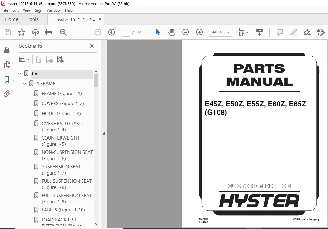
Hyster E45Z E50Z E55Z E60Z E65Z (G108) Parts Manual – PDF DOWNLOAD
Original price was: $89.95.$29.95Current price is: $29.95.
Hyster E45Z E50Z E55Z E60Z E65Z (G108) Parts Manual – PDF DOWNLOAD
Instant PDF Download
Available immediately
Save to Your Device
Download & keep forever
Antivirus Scanned
100% virus-free
Trusted Worldwide
175,000+ customers
Description
Hyster E45Z E50Z E55Z E60Z E65Z (G108) Parts Manual – PDF DOWNLOAD
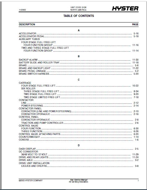
TABLE OF CONTENTS:
Hyster E45Z E50Z E55Z E60Z E65Z (G108) Parts Manual – PDF DOWNLOAD
toc.....................................................  1
	1 FRAME............................................. 17
		FRAME (Figure 1-1).............................. 20
		COVERS (Figure 1-2)............................. 24
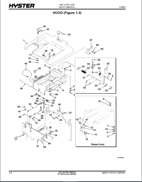
		HOOD (Figure 1-3)............................... 26
		OVERHEAD GUARD (Figure 1-4)..................... 30
		COUNTERWEIGHT (Figure 1-5)...................... 32
		NON-SUSPENSION SEAT (Figure 1-6)................ 34
		SUSPENSION SEAT (Figure 1-7).................... 36
		FULL SUSPENSION SEAT (Figure 1-8)............... 38
		FULL SUSPENSION SEAT (Figure 1-9)............... 40
		LABELS (Figure 1-10)............................ 42
		LOAD BACKREST EXTENSION (Figure 1-11)........... 46
		FORK (Figure 1-12).............................. 48
	2 ELECTRICAL SYSTEM................................. 51
		ELECTRICAL (Figure 2-1)......................... 54
		DASH DISPLAY (Figure 2-2)....................... 57
		CONTROL PANEL (Figure 2-3)...................... 58
		CONTROL PANEL (Figure 2-4)...................... 60
		CONTACTOR PANEL (Figure 2-5).................... 62
		CONTACTOR (Figure 2-6).......................... 64
		CONTACTOR (Figure 2-7).......................... 66
		CONTACTOR PANEL (Figure 2-8).................... 68
		WIRE HARNESS (Figure 2-9)....................... 70
		WIRE HARNESS (Figure 2-10)...................... 72
	3 DRIVE UNIT........................................ 73
		DRIVE AXLE (Figure 3-1)......................... 76
		TRANSMISSION AND DIFFERENTIAL (Figure 3-2)...... 78
		DRIVE UNIT INSTALLATION (Figure 3-3)............ 82
		TRACTION MOTOR (Figure 3-4)..................... 84
		TIRE AND WHEEL (Figure 3-5)..................... 86
	4 STEERING SYSTEM................................... 89
		STEERING POD (Figure 4-1)....................... 92
		SHIFT LEVER (Figure 4-2)........................ 94
		STEERING CONTROL UNIT (Figure 4-3).............. 96
		STEERING HYDRAULIC (Figure 4-4)................. 98
		STEERING CYLINDER (Figure 4-5)..................100
		GEAR PUMP (Figure 4-6)..........................102
		STEERING MOTOR (Figure 4-7).....................104
		STEERING AXLE (Figure 4-8)......................106
		TIRE AND WHEEL (Figure 4-9).....................108
	5 BRAKE/ACCELERATOR SYSTEM..........................109
		BRAKE PEDAL LINKAGE (Figure 5-1)................112
		MASTER CYLINDER (Figure 5-2)....................114
		BRAKE (Figure 5-3)..............................116
		PARK BRAKE LINKAGE (Figure 5-4).................118
		PARK BRAKE LINKAGE (Figure 5-5).................122
		PARK BRAKE (Figure 5-6).........................124
		ACCELERATOR (Figure 5-7)........................126
		ACCELERATOR PEDAL (Figure 5-8)..................128
		BRAKE SWITCH HARNESS (Figure 5-9)...............130
	6 HYDRAULIC SYSTEM..................................131
		HYDRAULIC (Figure 6-1)..........................134
		HYDRAULIC PUMP (Figure 6-2).....................137
		HYDRAULIC PUMP (Figure 6-3).....................138
		HYDRAULIC PUMP (Figure 6-4).....................140
		HYDRAULIC MOTOR MOUNT (Figure 6-5)..............142
		HYDRAULIC MOTOR (Figure 6-6)....................144
		HYDRAULIC MOTOR (Figure 6-7)....................146
		HYDRAULIC MOTOR (Figure 6-8)....................148
		TILT CYLINDER (Figure 6-9)......................150
		CONTROL VALVE ATTACHING PARTS (Figure 6-10).....152
		HAND LEVER (Figure 6-11)........................156
		CONTROL VALVE (Figure 6-12).....................158
		CONTROL VALVE (Figure 6-13).....................162
		HYDRAULIC TANK (Figure 6-14)....................166
		MAST INSTALLATION (Figure 6-15).................168
	7 MAST-TWO STAGE LIMITED FREE-LIFT..................171
		OUTER MAST (Figure 7-1).........................174
		INNER MAST (Figure 7-2).........................176
		LIFT (Figure 7-3)...............................180
		LIFT CYLINDER (Figure 7-4)......................183
		LIFT CYLINDER (Figure 7-5)......................186
		CARRIAGE (Figure 7-6)...........................190
		HEADER HOSE (Figure 7-7)........................192
	8 MAST-THREE STAGE FULL FREE-LIFT...................197
		OUTER MAST (Figure 8-1).........................200
		INTERMEDIATE MAST (Figure 8-2)..................204
		INNER MAST (Figure 8-3).........................208
		MAIN LIFT (Figure 8-4)..........................212
		FREE-LIFT (Figure 8-5)..........................216
		MAIN CYLINDER (Figure 8-6)......................220
		MAIN CYLINDER (Figure 8-7)......................224
		FREE-LIFT CYLINDER (Figure 8-8).................228
		CARRIAGE (Figure 8-9)...........................232
		HEADER HOSE (Figure 8-10).......................234
	9 MAST-TWO STAGE FULL FREE-LIFT.....................239
		OUTER MAST (Figure 9-1).........................242
		INNER MAST (Figure 9-2).........................244
		MAIN LIFT (Figure 9-3)..........................246
		FREE-LIFT (Figure 9-4)..........................248
		FREE-LIFT (Figure 9-5)..........................250
		MAIN LIFT CYLINDER (Figure 9-6).................253
		MAIN LIFT CYLINDER (Figure 9-7).................255
		FREE-LIFT CYLINDER (Figure 9-8).................257
		CARRIAGE (Figure 9-9)...........................260
		HEADER HOSE (Figure 9-10).......................262
	10 MAST-FOUR STAGE FULL FREE-LIFT...................265
		OUTER MAST (Figure 10-1)........................268
		INTERMEDIATE MAST (Figure 10-2).................270
		INTERMEDIATE MAST (Figure 10-3).................272
		INNER MAST (Figure 10-4)........................274
		MAIN LIFT (Figure 10-5).........................276
		FREE-LIFT (Figure 10-6).........................278
		MAIN CYLINDER (Figure 10-7).....................281
		MAIN CYLINDER (Figure 10-8).....................284
		FREE-LIFT CYLINDER (Figure 10-9)................286
		CARRIAGE (Figure 10-10).........................288
		HEADER HOSE (Figure 10-11)......................290
	11 OPTIONS..........................................293
		INTEGRAL SIDE-SHIFT (Figure 11-1)...............296
		INTEGRAL SIDE-SHIFT (Figure 11-2)...............298
		INTEGRAL SIDE-SHIFT (Figure 11-3)...............300
		INTEGRAL SIDE-SHIFT CYLINDER (Figure 11-4)......302
		INTEGRAL SIDE-SHIFT (Figure 11-5)...............304
		INTEGRAL SIDE-SHIFT (Figure 11-6)...............305
		INTEGRAL SIDE-SHIFT (Figure 11-7)...............306
		AUXILIARY TUBES (Figure 11-8)...................308
		AUXILIARY TUBES (Figure 11-9)...................310
		BATTERY SLIDE AND ROLLER TRAY (Figure 11-10)....312
		BRAKE AND BACKUP LIGHT (Figure 11-11)...........316
		DRIVE AND REAR LIGHTS (Figure 11-12)............318
		STROBE LIGHT (Figure 11-13).....................320
		SPOTLIGHT (Figure 11-14)........................322
		DC CONVERTOR (Figure 11-15).....................323
		BACKUP ALARM (Figure 11-16).....................324
		WIRE HARNESS (Figure 11-17).....................326
		WIRE HARNESS (Figure 11-18).....................327
		WIRE HARNESS (Figure 11-19).....................328
DESCRIPTION:
Hyster E45Z E50Z E55Z E60Z E65Z (G108) Parts Manual – PDF DOWNLOAD
HOW TO USE THE ILLUSTRATED PARTS MANUAL :
- This parts manual describes and illustrates assemblies, sub-assemblies, and detail parts needed for service replacement.
- The different constructions are indicated by keys and footnotes. The call outs correspond to descriptions found on the next page.
HOW TO FIND THE DESIRED PART NUMBER
WHEN THE PART NUMBER AND THE NEXT HIGHER ASSEMBLY IS NOT KNOWN:
1. Determine the function and application of the part required. Turn to the Sections Page. Choose the general area of reference most likely to include the part.
WHEN THE PART NUMBER AND THE NEXT HIGHER ASSEMBLY IS NOT KNOWN:
1. Determine the function and application of the part required. Turn to the Sections Page. Choose the general area of reference most likely to include the part.
2. Turn to the section you chose. Use the Section Table of Contents to determine the assembly which would normally contain the part required. Then locate the part on the assembly breakdown page.
WHEN THE PART NUMBER IS NOT KNOWN AND THE NEXT HIGHER ASSEMBLY IS KNOWN:
3. Determine the assembly the required part is used on. Turn to the Table of Contents (Page i).
WHEN THE PART NUMBER IS NOT KNOWN AND THE NEXT HIGHER ASSEMBLY IS KNOWN:
3. Determine the assembly the required part is used on. Turn to the Table of Contents (Page i).
4. Locate the assembly the required part is used on and turn to the page indicated for that assembly. Then locate the part on the assembly breakdown page.
WHEN THE PART NUMBER IS KNOWN:
5. Use the Numerical Index (Page 12-1) to find the part number. Turn to the page listed and locate the part as indicated by the item number.
GENERAL:
The assembly breakdowns include part numbers, descriptions, quantities required, keys and footnotes to help in selecting correct parts.
WHEN THE PART NUMBER IS KNOWN:
5. Use the Numerical Index (Page 12-1) to find the part number. Turn to the page listed and locate the part as indicated by the item number.
GENERAL:
The assembly breakdowns include part numbers, descriptions, quantities required, keys and footnotes to help in selecting correct parts.
6. Parts Super session Information. Part numbers that have this history will be displayed in the parts list in the order that they were superseded (from oldest to newest). The superseded part numbers will be shown with a line through them.
- Five periods in the PART NO. column (. . . . .) indicate that the part is either Not Serviced Separately or there is a reference to another figure. A figure reference is denoted by a pointing hand followed by a figure number in the DESCRIPTION column (Figure 10)
7. Keys are used to show two or more similar assemblies, RH and LH assembly parts, etc. Select the appropriate key, “A”, “B”, “C”, “D”, or “E” and the corresponding quantity column to find the required parts. Two periods in the QTY column (..) indicate that the part is not used for that assembly.
IMAGES PREVIEW OF THE MANUAL:
HYSTER E45Z E50Z E55Z E60Z E65Z (G108) PARTS MANUAL – PDF DOWNLOAD:
PLEASE NOTE:
- This is not a physical manual but a digital manual – meaning no physical copy will be couriered to you. The manual can be yours in the next 2 mins as once you make the payment, you will be directed to the download page IMMEDIATELY.
- This is the same manual used by the dealers inorder to diagnose your vehicle of its faults.
- Require some other service manual or have any queries: please WRITE to us at [email protected]
S.V