Trusted Business
Verified & Licensed
Virus Free Files
100% Safe Downloads
Secure Payment
SSL Protected
Instant Delivery
Available Immediately
Sale!
Hyster Electric E100XL3 E100XL3S E120XL3 E70XL3 E80XL3 (C098) Parts Manual – PDF DOWNLOAD
Original price was: $85.95.$29.95Current price is: $29.95.
Hyster Electric E100XL3 E100XL3S E120XL3 E70XL3 E80XL3 (C098) Parts Manual – PDF DOWNLOAD
Instant PDF Download
Available immediately
Save to Your Device
Download & keep forever
Antivirus Scanned
100% virus-free
Trusted Worldwide
175,000+ customers
Description
Hyster Electric E100XL3 E100XL3S E120XL3 E70XL3 E80XL3 (C098) Parts Manual – PDF DOWNLOAD
DESCRIPTION:
Hyster Electric E100XL3 E100XL3S E120XL3 E70XL3 E80XL3 (C098) Parts Manual – PDF DOWNLOAD
HOW TO USE THE ILLUSTRATED PARTS MANUAL :
- This parts manual describes and illustrates assemblies, subassemblies, and detail parts needed for service replacement.
- The different constructions are indicated by keys and footnotes. The callouts correspond to descriptions found on the next page.
HOW TO FIND THE DESIRED PART NUMBER
WHEN THE PART NUMBER AND THE NEXT HIGHER ASSEMBLY IS NOT KNOWN:
1. Determine the function and application of the part required. Turn to the Sections Page. Choose the general area of reference most likely to include the part.
WHEN THE PART NUMBER AND THE NEXT HIGHER ASSEMBLY IS NOT KNOWN:
1. Determine the function and application of the part required. Turn to the Sections Page. Choose the general area of reference most likely to include the part.
2. Turn to the section you chose. Use the Section Table of Contents to determine the assembly which would normally contain the part required. Then locate the part on the assembly breakdown page.
WHEN THE PART NUMBER IS NOT KNOWN AND THE NEXT HIGHER ASSEMBLY IS KNOWN:
3. Determine the assembly the required part is used on. Turn to the Table of Contents (Page i).
WHEN THE PART NUMBER IS NOT KNOWN AND THE NEXT HIGHER ASSEMBLY IS KNOWN:
3. Determine the assembly the required part is used on. Turn to the Table of Contents (Page i).
4. Locate the assembly the required part is used on and turn to the page indicated for that assembly. Then locate the part on the assembly breakdown page.
WHEN THE PART NUMBER IS KNOWN:
5. Use the Numerical Index (Page 11-1) to find the part number. Turn to the page listed and locate the part as indicated by the item number.
GENERAL:
The assembly breakdowns include part numbers, descriptions, quantities required, keys and footnotes to help in selecting correct parts.
6. Parts Supersession Information. Part numbers that have this history will be displayed in the parts list in the order that they were superseded (from oldest to newest). The superseded part numbers will be shown with a line through them.
- Five periods in the PART NO. column (. . . . .) indicate that the part is either Not Serviced Separately or there is a reference to another figure. A figure reference is denoted by a pointing hand followed by a figure number in the DESCRIPTION column (FFigure 10)
7. Keys are used to show two or more similar assemblies, RH and LH assembly parts, etc. Select the appropriate key, “A”, “B”, “C”, “D”, or “E” and the corresponding quantity column to find the required parts. Two periods in the QTY column (..) indicate that the part is not used for that assembly.
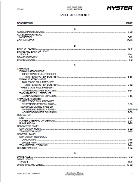
TABLE OF CONTENTS:
Hyster Electric E100XL3 E100XL3S E120XL3 E70XL3 E80XL3 (C098) Parts Manual – PDF DOWNLOAD
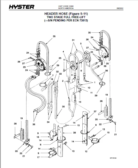
toc....................................................  1
	1.................................................. 19
		SEMI-SUSPENSION SEAT (Figure 1-1).............. 22
		SEMI-SUSPENSION SEAT (Figure 1-2).............. 26
		SEMI SUSPENSION SEAT (Figure 1-3).............. 30
		NON-SUSPENSION SEAT (Figure 1-4)............... 32
		FLOORPLATES AND COVERS (Figure 1-5)............ 36
		HOOD (Figure 1-6).............................. 40
		OVERHEAD GUARD (Figure 1-7).................... 42
		COUNTERWEIGHT (Figure 1-8)..................... 44
		LABELS (Figure 1-9)............................ 46
	2.................................................. 49
		ELECTRICAL (Figure 2-1)........................ 52
		ELECTRICAL (Figure 2-2)........................ 56
		ELECTRICAL (Figure 2-3)........................ 60
		CONTROL PANEL (Figure 2-4)..................... 64
		CONTROL PANEL (Figure 2-5)..................... 66
		CONTROL PANEL (Figure 2-6)..................... 68
		CONTACTOR PANEL (Figure 2-7)................... 70
		CONTACTOR PANEL (Figure 2-8)................... 72
		CONTACTOR (Figure 2-9)......................... 74
		CONTACTOR (Figure 2-10)........................ 76
		CONTACTOR (Figure 2-11)........................ 78
		WIRE HARNESS (Figure 2-12)..................... 80
	3.................................................. 83
		DRIVE AXLE (Figure 3-1)........................ 86
		TRANSMISSION ASSEMBLY (Figure 3-2)............. 90
		TRACTION MOTOR (Figure 3-3).................... 94
		TRACTION MOTOR (Figure 3-4).................... 96
	4.................................................. 99
		STEERING COLUMN (Figure 4-1)...................102
		STEERING COLUMN (Figure 4-2)...................106
		STEERING LINES (Figure 4-3)....................110
		STEERING AXLE (Figure 4-4).....................112
		STEERING CONTROL UNIT (Figure 4-5).............116
		STEERING CONTROL UNIT (Figure 4-6).............118
		STEERING CONTROL UNIT (Figure 4-7).............120
		STEERING CYLINDER (Figure 4-8).................122
		STEERING PUMP (Figure 4-9).....................124
		STEER MOTOR (Figure 4-10)......................126
		STEERING MOTOR (Figure 4-11)...................128
	5..................................................131
		BRAKE LINKAGE (Figure 5-1).....................134
		MASTER CYLINDER (Figure 5-2)...................136
		BRAKE ASSEMBLY (Figure 5-3)....................138
		PARK BRAKE (Figure 5-4)........................142
		PARK BRAKE LINKAGE (Figure 5-5)................144
		SEAT BRAKE (Figure 5-6)........................148
		SEAT BRAKE (Figure 5-7)........................150
		ACCELERATOR LINKAGE (Figure 5-8)...............152
		ACCELERATOR PEDAL (Figure 5-9).................154
	6..................................................157
		HYDRAULICS (Figure 6-1)........................160
		HYDRAULICS (Figure 6-2)........................164
		HYDRAULIC PUMP (Figure 6-3)....................168
		HYDRAULIC PUMP (Figure 6-4)....................170
		HYDRAULIC MOTOR (Figure 6-5)...................172
		HYDRAULIC MOTOR (Figure 6-6)...................174
		HYDRAULIC MOTOR (Figure 6-7)...................176
		HYDRAULIC MOTOR (Figure 6-8)...................178
		HYDRAULIC FILTER (Figure 6-9)..................180
		HYDRAULIC LINKAGE (Figure 6-10)................182
		HYDRAULIC CONTROL (Figure 6-11)................184
		HYDRAULIC VALVE (Figure 6-12)..................188
		HYDRAULIC VALVE (Figure 6-13)..................192
		HYDRAULIC VALVE (Figure 6-14)..................196
		HYDRAULIC VALVE (Figure 6-15)..................200
		TILT CYLINDER (Figure 6-16)....................204
		TILT CYLINDER (Figure 6-17)....................206
		MAST INSTALLATION (Figure 6-18)................208
	7..................................................211
		OUTER MAST (Figure 7-1)........................214
		OUTER MAST (Figure 7-2)........................216
		INNER MAST (Figure 7-3)........................218
		INNER MAST (Figure 7-4)........................220
		MAIN LIFT (Figure 7-5).........................222
		MAIN LIFT (Figure 7-6).........................226
		MAIN CYLINDER (Figure 7-7).....................230
		MAIN CYLINDER (Figure 7-8).....................234
		MAIN CYLINDER (Figure 7-9).....................236
		MAIN CYLINDER (Figure 7-10)....................238
		HEADER HOSE (Figure 7-11)......................240
		HEADER HOSE (Figure 7-12)......................244
		CARRIAGE ASSEMBLY (Figure 7-13)................248
		CARRIAGE ASSEMBLY (Figure 7-14)................252
		LOAD BACKREST EXTENSION (Figure 7-15)..........254
		FORK (Figure 7-16).............................255
	8..................................................257
		OUTER MAST (Figure 8-1)........................260
		OUTER MAST (Figure 8-2)........................262
		INTERMEDIATE MAST (Figure 8-3).................264
		INTERMEDIATE MAST (Figure 8-4).................266
		INNER MAST (Figure 8-5)........................268
		INNER MAST (Figure 8-6)........................270
		MAIN LIFT (Figure 8-7).........................272
		MAIN LIFT (Figure 8-8).........................276
		MAIN LIFT CYLINDER (Figure 8-9)................280
		MAIN LIFT CYLINDER (Figure 8-10)...............284
		FREE LIFT (Figure 8-11)........................288
		FREE LIFT (Figure 8-12)........................292
		FREE-LIFT CYLINDER (Figure 8-13)...............296
		FREE LIFT CYLINDER (Figure 8-14)...............300
		HEADER HOSE (Figure 8-15)......................304
		HEADER HOSE (Figure 8-16)......................308
		CARRIAGE (Figure 8-17).........................312
		CARRIAGE ASSEMBLY (Figure 8-18)................314
		CARRIAGE (Figure 8-19).........................316
		LOAD BACKREST EXTENSION (Figure 8-20)..........318
		FORK (Figure 8-21).............................319
	9..................................................321
		OUTER MAST (Figure 9-1)........................324
		OUTER MAST AND MAIN LIFT (Figure 9-2)..........326
		INNER MAST (Figure 9-3)........................330
		INNER MAST AND FREE-LIFT (Figure 9-4)..........332
		MAIN LIFT (Figure 9-5).........................336
		FREE LIFT (Figure 9-6).........................340
		MAIN LIFT CYLINDER (Figure 9-7)................344
		MAIN LIFT CYLINDER (Figure 9-8)................348
		FREE-LIFT CYLINDER (Figure 9-9)................352
		FREE LIFT CYLINDER (Figure 9-10)...............356
		HEADER HOSE (Figure 9-11)......................360
		HEADER HOSE (Figure 9-12)......................364
		CARRIAGE (Figure 9-13).........................368
		CARRIAGE ASSEMBLY (Figure 9-14)................372
		CARRIAGE (Figure 9-15).........................374
		LOAD BACKREST EXTENSION (Figure 9-16)..........376
		FORK (Figure 9-17).............................377
	10.................................................379
		DRIVE LIGHTS (Figure 10-1).....................382
		BRAKE AND BACK-UP LIGHT (Figure 10-2)..........384
		STROBE LIGHT (Figure 10-3).....................386
		BACK-UP ALARM (Figure 10-4)....................388
		STEER TIRE AND WHEEL (Figure 10-5).............390
		SIDE-SHIFT CARRIAGE (Figure 10-6)..............392
		INTEGRAL SIDE-SHIFT (Figure 10-7)..............394
		INTEGRAL SIDE-SHIFT (Figure 10-8)..............396
		INTEGRAL SIDESHIFT CARRIAGE (Figure 10-9)......398
		INTEGRAL SIDE-SHIFT CARRIAGE (Figure 10-10)....400
		INTEGRAL SIDE-SHIFT CARRIAGE (Figure 10-11)....402
		INTEGRAL SIDE-SHIFT (Figure 10-12).............404
		INTEGRAL SIDE-SHIFT CARRIAGE (Figure 10-13)....406
		INTEGRAL SIDE-SHIFT CARRIAGE (Figure 10-14)....408
		INTEGRAL SIDE-SHIFT (Figure 10-15).............410
		INTEGRAL SIDE-SHIFT CARRIAGE (Figure 10-16)....412
		INTEGRAL SIDE-SHIFT (Figure 10-17).............414
		INTEGRAL SIDE-SHIFT CARRIAGE (Figure 10-18)....416
		INTEGRAL SIDE-SHIFT CARRIAGE (Figure 10-19)....418
		INTEGRAL SIDE-SHIFT (Figure 10-20).............420
		INTEGRAL SIDE-SHIFT CARRIAGE (Figure 10-21)....422
		SIDE-SHIFT CYLINDER (Figure 10-22).............424
		ACCUMULATOR (Figure 10-23).....................426
		HEADER HOSE (Figure 10-24).....................428
		HEADER HOSE (Figure 10-25).....................430
		DRIVE TIRE AND WHEEL (Figure 10-26)............432
IMAGES PREVIEW OF THE MANUAL:
HYSTER ELECTRIC E100XL3 E100XL3S E120XL3 E70XL3 E80XL3 (C098) PARTS MANUAL – PDF DOWNLOAD:
PLEASE NOTE:
- This is the same manual used by the DEALERSHIPS to SERVICE your vehicle.
- The manual can be all yours – Once payment is complete, you will be taken to the download page from where you can download the manual. All in 2-5 minutes time!!
- Need any other service / repair / parts manual, please feel free to contact us at heydownloadss @gmail.com . We may surprise you with a nice offer
S.V