Trusted Business
Verified & Licensed
Virus Free Files
100% Safe Downloads
Secure Payment
SSL Protected
Instant Delivery
Available Immediately
Sale!
Hyster ELECTRIC R30XM2 R30XMA2 R30XMF2 (G118) Parts Manual – PDF DOWNLOAD
Original price was: $89.95.$29.95Current price is: $29.95.
Hyster ELECTRIC R30XM2 R30XMA2 R30XMF2 (G118) Parts Manual – PDF DOWNLOAD
Instant PDF Download
Available immediately
Save to Your Device
Download & keep forever
Antivirus Scanned
100% virus-free
Trusted Worldwide
175,000+ customers
Description
Hyster ELECTRIC R30XM2 R30XMA2 R30XMF2 (G118) Parts Manual – PDF DOWNLOAD
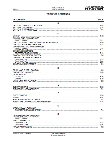
TABLE OF CONTENTS:
Hyster ELECTRIC R30XM2 R30XMA2 R30XMF2 (G118) Parts Manual – PDF DOWNLOAD
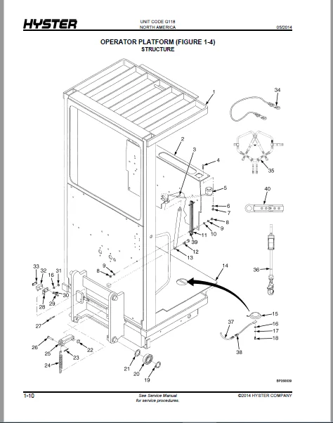
Frame............................................................................ 15
	HOODS AND COVERS............................................................. 18
	CONTROL COMPARTMENT.......................................................... 22
	DECAL AND PLATE LOCATION..................................................... 24
	OPERATOR PLATFORM STRUCTURE.................................................. 26
	OPERATOR PLATFORM ASSEMBLY - W/ SIDE RAILS .................................. 30
	OPERATOR PLATFORM ASSEMBLY - W/ SIDE GATES .................................. 34
	OPERATOR PLATFORM INTERFACE.................................................. 38
	OPERATOR PLATFORM CONTROLS................................................... 40
	PIVOTING HANDRAIL............................................................ 42
	LOAD WHEEL SINGLE............................................................ 44
	LOAD WHEEL TANDEM............................................................ 46
	CASTER....................................................................... 48
	FORKS........................................................................ 50
	PALLET CLAMP ASSEMBLY........................................................ 52
ELECTRICAL SYSTEM................................................................ 55
	ELECTRICAL ARRANGEMENT....................................................... 58
	CONSOLE ELECTRICAL SYSTEM.................................................... 62
	COLD STORAGE CONSOLE ELECTRICAL ASSEMBLY..................................... 66
	CONSOLE ELECTRICAL FREEZER/ARCTIC  (12/2005 →) .............................. 68
	BATTERY CONNECTOR ASSEMBLY................................................... 70
	BATTERY DISCONNECT........................................................... 72
	CONTACTOR PANEL ASSEMBLY 24/36 VOLT 'E'...................................... 74
	CONTACTOR PANEL ASSEMBLY 24/36 VOLT 'EE'..................................... 76
	MAIN/TRACTION CONTACTOR 24/36 VOLT 'E'....................................... 78
	MAIN/TRACTION CONTACTOR 24/36 VOLT 'EE'...................................... 79
	HOIST CONTACTOR 24/36 VOLT 'E'............................................... 80
	HOIST CONTACTOR 24/36 VOLT 'EE'.............................................. 82
	MULTI-FUNCTION CONTROL HANDLE ASSEMBLY....................................... 84
	MULTI-FUNCTION CONTROL HANDLE................................................ 86
DRIVE UNIT....................................................................... 89
	DRIVE UNIT INSTALLATION...................................................... 92
	MASTER DRIVE UNIT............................................................ 96
	MASTER DRIVE UNIT 18.0:1 GEAR RATIO  (7/2002 ↔ S/N G118N01979B) .............100
	MASTER DRIVE UNIT 18.0:1 GEAR RATIO  (S/N G118N01980B ↔ 10/2006) ............102
	MASTER DRIVE UNIT 20.2:1 GEAR RATIO  (S/N G118N01663Z ↔ S/N G118N01979B) ....106
	MASTER DRIVE UNIT 20.2:1 GEAR RATIO  (S/N G118N01980B ↔ 10/2006) ............108
	MASTER DRIVE UNIT 20.2:1 GEAR RATIO  (10/2006 →) ............................110
	MASTER DRIVE UNIT 18.0:1 GEAR RATIO  (10/2006 →) ............................112
	DRIVE MOTOR..................................................................116
	DRIVE MOTOR..................................................................120
	ELECTRIC BRAKE...............................................................122
STEERING SYSTEM..................................................................125
	STEERING GEAR AND MOTOR......................................................128
	STEERING GEAR AND MOTOR......................................................130
	STEERING CHAIN AND SENSOR....................................................132
	STEER ASSEMBLY RETURN-TO-CENTER (RTC)........................................134
	MULTI-TURN STEER ASSEMBLY....................................................136
HYDRAULIC SYSTEM.................................................................139
	HYDRAULIC ARRANGEMENT........................................................142
	HYDRAULIC CONTROL VALVE......................................................146
	HYDRAULIC TANK ASSEMBLY......................................................148
	LIFT MOTOR...................................................................150
	HYDRAULIC PUMP ASSEMBLY......................................................152
MAST-THREE STAGE.................................................................155
	OUTER, INTERMEDIATE, AND INNER MAST THREE STAGE..............................158
	MAIN LIFT CYLINDER ARRANGEMENT THREE STAGE...................................162
	MAIN LIFT CYLINDER THREE STAGE...............................................164
	CHAINS, PINS, AND ANCHORS THREE STAGE........................................168
	CONNECTING AND TAKE-UP HOSES THREE STAGE.....................................172
	LOWER COILED CABLE ASSEMBLY THREE STAGE......................................174
	UPPER COILED CABLE ASSEMBLY THREE STAGE......................................176
	HEIGHT ENCODER ASSEMBLY THREE STAGE..........................................178
	WIRE TAKE-UP 'EE' AND COLD STORAGE - 5.5 INCH MAST ..........................180
	WIRE TAKE-UP 'EE' AND COLD STORAGE - 6 7/8 INCH MAST ........................182
OPTIONS..........................................................................185
	LIGHT AND FAN ASSEMBLY.......................................................188
	GUIDE ROLLER ASSEMBLY FACTORY INSTALLED OPTION...............................190
	BATTERY TRAY AND PULLER......................................................192
	FULL BODY FAN INSTALLATION...................................................194
	FIXED CONSOLE................................................................196
	WIRE GUIDANCE SENSORS........................................................198
	WIRE GUARD ASSEMBLY..........................................................200
	FURNITURE OVERHEAD GUARD WELDMENT............................................202
	COLD STORAGE HEATER PLATE....................................................204
	DIAGNOSTIC HANDSET...........................................................206
	WIRE DRIVER ASSEMBLY.........................................................208
FIELD CONVERSION KITS............................................................211
	LIGHT CONVERSION KIT.........................................................214
	LIFT AND LOWER LIMIT KITS....................................................214
	TRACTION CONTROL KIT.........................................................214
NUMERICAL INDEX..................................................................215
DESCRIPTION:
Hyster ELECTRIC R30XM2 R30XMA2 R30XMF2 (G118) Parts Manual – PDF DOWNLOAD
HOW TO USE THE ILLUSTRATED PARTS MANUAL :
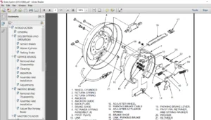
- This parts manual describes and illustrates assemblies, sub-assemblies, and detail parts needed for service replacement.
- The different constructions are indicated by keys and footnotes. The call outs correspond to descriptions found on the next page.
HOW TO FIND THE DESIRED PART NUMBER
WHEN THE PART NUMBER AND THE NEXT HIGHER ASSEMBLY IS NOT KNOWN:
1. Determine the function and application of the part required. Turn to the Sections Page. Choose the general area of reference most likely to include the part.
WHEN THE PART NUMBER AND THE NEXT HIGHER ASSEMBLY IS NOT KNOWN:
1. Determine the function and application of the part required. Turn to the Sections Page. Choose the general area of reference most likely to include the part.
2. Turn to the section you chose. Use the Section Table of Contents to determine the assembly which would normally contain the part required. Then locate the part on the assembly breakdown page.
WHEN THE PART NUMBER IS NOT KNOWN AND THE NEXT HIGHER ASSEMBLY IS KNOWN:
3. Determine the assembly the required part is used on. Turn to the Table of Contents (Page i).
WHEN THE PART NUMBER IS NOT KNOWN AND THE NEXT HIGHER ASSEMBLY IS KNOWN:
3. Determine the assembly the required part is used on. Turn to the Table of Contents (Page i).
4. Locate the assembly the required part is used on and turn to the page indicated for that assembly. Then locate the part on the assembly breakdown page.
WHEN THE PART NUMBER IS KNOWN:
5. Use the Numerical Index (Page 9-1) to find the part number. Turn to the page listed and locate the part as indicated by the item number.
GENERAL:
The assembly breakdowns include part numbers, descriptions, quantities required, keys and footnotes to help in selecting correct parts.
6. Parts Super session Information. Part numbers that have this history will be displayed in the parts list in the order that they were superseded (from oldest to newest). The superseded part numbers will be shown with a line through them.
- Five periods in the PART NO. column (. . . . .) indicate that the part is either Not Serviced Separately or there is a reference to another figure. A figure reference is denoted by a pointing hand followed by a figure number in the DESCRIPTION column (Figure 10)
7. Keys are used to show two or more similar assemblies, RH and LH assembly parts, etc. Select the appropriate key, “A”, “B”, “C”, “D”, or “E” and the corresponding quantity column to find the required parts. Two periods in the QTY column (..) indicate that the part is not used for that assembly.
IMAGES PREVIEW OF THE MANUAL:
HYSTER ELECTRIC R30XM2 R30XMA2 R30XMF2 (G118) PARTS MANUAL – PDF DOWNLOAD:
PLEASE NOTE:
- This is the SAME exact manual used by your dealers to fix your vehicle.
- The same can be yours in the next 2-3 mins as you will be directed to the download page immediately after paying for the manual.
- Any queries / doubts regarding your purchase, please feel free to contact [email protected]
S.V