Trusted Business
Verified & Licensed
Virus Free Files
100% Safe Downloads
Secure Payment
SSL Protected
Instant Delivery
Available Immediately
Sale!

Hyster Forklift H40 60XL B177 & C177 service manual – PDF DOWNLOAD
Original price was: $92.95.$32.95Current price is: $32.95.
Hyster Forklift H40 60XL B177 & C177 service manual
Instant PDF Download
Available immediately
Save to Your Device
Download & keep forever
Antivirus Scanned
100% virus-free
Trusted Worldwide
175,000+ customers
Description
Hyster Forklift H40 60XL B177 & C177 service manual
File Details:
Hyster Forklift H40 60XL B177 & C177 service manual
Language : English
Pages : 537
Size : 14.0 MB
Downloadable : Yes
Format : PDF
HYSTER FORKLIFT H40 60XL B177 & C177 SERVICE MANUAL – PDF DOWNLOAD:
Image Preview:
Description:
Hyster Forklift H40 60XL B177 & C177 service manual
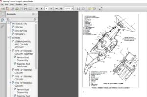
- GENERAL This section has a description and the repair procedures for the alternator with a voltage regulator as part of the alternator. CAUTION When using an arc welder, always disconnect the ground lead from the lift truck battery to prevent alternator or battery damage. Attach the welding ground clamp as close to the weld area as possible to prevent welding current from damaging the bearings. The diodes and resistors in the electrical system can be damaged if the following cautions are not followed
- : • Do not disconnect the battery when the engine is running. The voltage surge can damage the diodes and resistors in the electrical system. • Do not disconnect an electric wire before the engine is stopped and the switches are “OFF”. • Do not cause a short–circuit by connecting the electric wires to the wrong terminals. Make sure a correct identification is made of the wire before it is connected. • Make sure a battery is the correct voltage and polarity before it is connected.
- Do not check for current flow by making a spark because the electronic components can be damaged. NOTE: Information on alternators manufactured outside the United States is in the SRM (service repair manual) sections for lift trucks that use those alternators. DESCRIPTION (See FIGURE 1. and FIGURE 2.) NOTE: For this SRM section, the alternators are in two groups, Type A and Type B. The two types are very similar, but the Type A alternators have a set of three diodes (diode set) as well as the diode bridge.
- The Type B alternator has zener diodes as part of the diodes in the diode bridge. This alternator does not have a diode set, but does have an additional fan inside the rear housing. The basic operation of both types is very similar. The alternator generates an alternating current when the engine is running. The alternator is either ON or OFF. The alternator generates maximum current when it is ON and no current when it is OFF. The regulator switches the alternator between ON and OFF to get the average current needed to charge the battery. Alternator output is directly changed by engine speed and rotor field current. The alternating current is changed to a direct current by the diode bridge inside the alternator.
Table of Contents:
Hyster Forklift H40 60XL B177 & C177 service manual
INTRODUCTION.............................................................................................  1
	GENERAL..............................................................................................  1
	DESCRIPTION..........................................................................................  1
REPAIRS..................................................................................................  3
	GENERAL..............................................................................................  3
	REMOVAL AND DISASSEMBLY (Type A).....................................................................  3
	CLEANING.............................................................................................  3
	ASSEMBLY (Type A)....................................................................................  4
	REMOVAL AND DISAASSEMBLY (Type B)....................................................................  6
	CLEANING.............................................................................................  8
	ASSEMBLY (Type B)....................................................................................  8
	INSTALLATION (Type A and Type B).....................................................................  9
CHECKS AND ADJUSTMENTS...................................................................................  9
	GENERAL..............................................................................................  9
	CHECK THE ALTERNATOR FOR LOW OUTPUT (Type A or Type B)............................................... 10
	CHECK THE ALTERNATOR FOR HIGH OUTPUT (Type A or Type B).............................................. 11
	CHECK THE CIRCUIT FOR THE BRUSHES.................................................................... 13
		Delco Alternators................................................................................ 13
		Motorola Alternators............................................................................. 13
	CHECK THE DIODES..................................................................................... 13
	CHECK THE DIODE BRIDGE............................................................................... 13
		Delco and Leece–Neville Alternators.............................................................. 13
		Motorola Alternators............................................................................. 13
	CHECK THE FIELD WINDING FOR THE ROTOR................................................................ 14
	CHECK THE WINDINGS IN THE STATOR..................................................................... 14
	CHECK THE VOLTAGE REGULATOR.......................................................................... 15
TROUBLESHOOTING.......................................................................................... 15
INTRODUCTION............................................................................................. 16
	GENERAL.............................................................................................. 16
SERVICE BRAKES AND PARKING BRAKE......................................................................... 16
	DESCRIPTION AND OPERATION............................................................................ 16
		Service Brakes................................................................................... 16
		Parking Brake.................................................................................... 17
	REMOVAL AND DISASSEMBLY OF THE 260 mm (10.25 in) SERVICE BRAKES...................................... 17
		Parking Brake.................................................................................... 19
	CLEANING............................................................................................. 20
	INSPECTION........................................................................................... 20
	ASSEMBLY AND INSTALLATION OF THE 260 mm (10.25 in) SERVICE BRAKES.................................... 20
		Adjustments...................................................................................... 23
		Parking Brake Installation....................................................................... 24
		Adjust The Parking Brake For Lift Trucks With 260 mm (10.25 in) Service Brakes................... 24
	REMOVAL AND DISASSEMBLY OF THE 310 mm (12.20 in) SERVICE BRAKES...................................... 26
		Parking Brake.................................................................................... 28
	CLEANING............................................................................................. 29
	INSPECTION........................................................................................... 29
	ASSEMBLY AND INSTALLATION OF THE 310 mm (12.20 in) SERVICE BRAKES.................................... 29
		Adjustments...................................................................................... 31
		Parking brake.................................................................................... 32
		Adjust The Parking Brake For Lift Trucks With 310 mm (12.20 in) Service Brakes................... 32
	MASTER CYLINDER...................................................................................... 33
		Removal.......................................................................................... 33
		Repair........................................................................................... 33
		Installation..................................................................................... 33
		Cleaning And Inspection.......................................................................... 35
	MASTER CYLINDER WITH BRAKE BOOSTER................................................................... 37
		Operation........................................................................................ 37
		Repair........................................................................................... 37
CHECKS AND ADJUSTMENTS................................................................................... 39
	ADJUST THE SERVICE BRAKES............................................................................ 39
	TEST THE PARKING BRAKE SWITCH (MONOTROL PEDAL ONLY).................................................. 39
	REMOVE THE AIR FROM THE BRAKE SYSTEM................................................................. 40
	ADJUST THE INCHING/BRAKE PEDAL....................................................................... 40
	ADJUSTMENT OF THE NEUTRAL START SWITCH (LIFT TRUCKS WITH MONOTROL PEDAL)............................. 45
	TEST THE NEUTRAL START SWITCH (MONOTROL PEDAL)....................................................... 45
		Test 1........................................................................................... 45
		Test 2........................................................................................... 46
TORQUE SPECIFICATIONS.................................................................................... 46
TROUBLESHOOTING.......................................................................................... 46
LIFT TRUCK WEIGHTS*...................................................................................... 49
ENGINE SPECIFICATIONS.................................................................................... 49
ENGINE ELECTRICAL SPECIFICATIONS......................................................................... 50
HYDRAULIC SPECIFICATIONS................................................................................. 50
CAPACITIES............................................................................................... 51
LIFT TRUCK TRAVEL SPEEDS................................................................................. 51
TIRE SPECIFICATIONS...................................................................................... 51
MAST SPEEDS (Early A177* Units).......................................................................... 52
MAST SPEEDS (Later A177* Units).......................................................................... 52
MAST SPEEDS (B177* and C177* with Mazda M4-121G or Isuzu 240 Engines).................................... 53
MAST SPEEDS (C177* with GM 4-181 or Isuzu 4JB1 Engines).................................................. 53
TORQUE SPECIFICATIONS.................................................................................... 55
TORQUE SPECIFICATIONS.................................................................................... 56
COOLING SYSTEM........................................................................................... 58
	INTRODUCTION......................................................................................... 58
	DESCRIPTION.......................................................................................... 58
	RADIATOR............................................................................................. 58
	RADIATOR CAP......................................................................................... 58
	THERMOSTAT........................................................................................... 58
	WATER PUMP........................................................................................... 59
	FAN AND FAN SHROUD................................................................................... 59
REPAIRS.................................................................................................. 59
	COOLING SYSTEM CHECKS................................................................................ 59
		Exhaust Leaks.................................................................................... 59
	RADIATOR............................................................................................. 59
		Checks........................................................................................... 59
		Cleaning The Radiator............................................................................ 59
		Drain The Cooling System......................................................................... 61
		Fill The Cooling System.......................................................................... 61
	WATER PUMP........................................................................................... 61
		Checks........................................................................................... 61
	THERMOSTAT........................................................................................... 62
		Checks........................................................................................... 62
	FAN AND FAN SHROUD................................................................................... 62
TROUBLESHOOTING.......................................................................................... 63
FIGURE 1. HYDRAULIC SYSTEM SCHEMATIC..................................................................... 65
FIGURE 2. TRANSMISSION SCHEMATIC......................................................................... 66
FIGURE 3. INSTRUMENT PANEL ELECTRICAL DIAGRAM............................................................ 67
FIGURE 4. MAZDA ENGINE, GASOLINE/LPG WIRING SCHEMATIC.................................................... 69
FIGURE 5. MAZDA ENGINE, GASOLINE/LPG CABLE DIAGRAM (G and LPG Rating).................................... 71
FIGURE 6. MAZDA ENGINE, GASOLINE/LPG CABLE DIAGRAM (GS and LPS Rating)................................... 73
FIGURE 7. DIESEL ENGINE WIRING SCHEMATIC................................................................. 75
FIGURE 8. DIESEL ENGINE CABLE DIAGRAM (D Rating)......................................................... 77
FIGURE 9. DIESEL (SAFETY) ENGINE CABLE DIAGRAM (DS RATING)............................................... 79
FIGURE 10. GM ENGINE, GASOLINE/LPG WIRING DIAGRAM (GS and LPS Rating).................................... 81
FIGURE 11. GM ENGINE, GASOLINE/LPG CABLE DIAGRAM (G and LPG Rating)...................................... 83
FIGURE 12. GM ENGINE, GASOLINE/LPG CABLE DIAGRAM (GS and LPS Rating)..................................... 85
INTRODUCTION............................................................................................. 90
	GENERAL.............................................................................................. 90
	DESCRIPTION.......................................................................................... 90
REPAIRS.................................................................................................. 91
	REMOVAL.............................................................................................. 91
	CLEANING............................................................................................. 91
	INSPECTION........................................................................................... 91
	ASSEMBLY............................................................................................. 91
TROUBLESHOOTING.......................................................................................... 94
SPECIFICATIONS........................................................................................... 94
INTRODUCTION............................................................................................. 95
	GENERAL.............................................................................................. 95
	DESCRIPTION.......................................................................................... 95
		Starting System.................................................................................. 95
		Charging System.................................................................................. 95
		Vacuum Pump On Alternator (On Units With Brake Booster).......................................... 97
REPAIRS.................................................................................................. 98
	STARTER.............................................................................................. 98
		Removal And Disassembly.......................................................................... 98
		Assembly And Installation........................................................................ 98
	REPLACING GLOW PLUGS.................................................................................100
	ALTERNATOR (With Vaccum Pump)........................................................................100
		Removal And Disassembly..........................................................................100
		Cleaning.........................................................................................102
		Assembly And Installation........................................................................102
	ALTERNATOR (Without Vacuum Pump).....................................................................103
		Removal And Disassembly..........................................................................103
		Cleaning.........................................................................................105
		Assembly And Installation........................................................................105
	REGULATOR REPLACEMENT................................................................................106
CHECKS...................................................................................................106
	GENERAL..............................................................................................106
	STARTER..............................................................................................106
		Starter Operation................................................................................106
		Solenoid Coil Checks.............................................................................107
		Brush Length.....................................................................................107
		Brush Holder.....................................................................................107
		Armature.........................................................................................107
		Field Windings...................................................................................108
		Clutch And Bearings..............................................................................108
	COLD START AID.......................................................................................108
		Glow Plugs.......................................................................................108
		Resistor.........................................................................................108
	CHARGING CIRCUIT.....................................................................................108
		Check For Low Output.............................................................................108
		Check Ford High Output...........................................................................110
	ALTERNATOR...........................................................................................110
		Rotor Resistance.................................................................................110
		Diodes Circuit...................................................................................110
		Rotor Coil.......................................................................................111
		Stator Coil......................................................................................111
		Diode Assembly...................................................................................111
		Brushes And Bearings.............................................................................112
	REGULATOR (At Hydraulic Tank)........................................................................112
TROUBLESHOOTING..........................................................................................113
INTRODUCTION.............................................................................................116
	GENERAL..............................................................................................116
	DESCRIPTION..........................................................................................116
		Starting System..................................................................................116
		Ignition System..................................................................................116
		Charging System..................................................................................117
REPAIR...................................................................................................119
	STARTER..............................................................................................119
		Removal And Disassembly..........................................................................119
		Assembly And Installation........................................................................119
	BALLAST RESISTOR RELAY (Earlier Production)..........................................................121
	DISTRIBUTOR (Earlier Production With Contact Points).................................................121
		Removal And Disassembly..........................................................................121
		Assembly And Installation........................................................................123
	COIL REPLACEMENT.....................................................................................123
	DISTRIBUTOR (Later Production with Electronic Ignition System).......................................123
		Removal And Disassembly..........................................................................123
		Assembly And Installation........................................................................125
	ALTERNATOR (All Models)..............................................................................125
		Removal And Disassembly..........................................................................125
		Assembly And Installation........................................................................126
	REGULATOR REPLACEMENT (Earlier Production)...........................................................127
CHECKS AND ADJUSTMENTS...................................................................................128
	GENERAL..............................................................................................128
	STARTER..............................................................................................128
		Check Operation..................................................................................128
		Check Brush Length...............................................................................129
		Check Brush Holder...............................................................................129
		Armature.........................................................................................129
		Field Windings...................................................................................129
		Clutch And Bearing...............................................................................129
	BALLAST RESISTOR RELAY (Earlier Production)..........................................................129
	DISTRIBUTOR..........................................................................................130
		Distributor Contact Clearance....................................................................130
	SPARK PLUGS..........................................................................................131
	COIL AND BALLAST RESISTOR (Earlier Production).......................................................131
	ALTERNATOR...........................................................................................131
		Check For Low Output (Alternator With Separate Regulator)........................................131
		Check For Low Output (Alternator With Integral Regulator)........................................133
		Check For High Output (Alternator With Separate Regulator).......................................134
		Check For High Output (Alternator With Integral Regulator).......................................134
		Rotor Resistance (Alternator with Separate Regulator)............................................134
		Diodes Circuit (Alternator with Separate Regulator)..............................................135
		Diode Assembly (Alternator With Separate Regulator)..............................................135
		Check The Diodes, Diode Trio (Alternator with Integral Regulator)................................135
		Check The Rectifier Bridge (Alternator with Integral Regulator)..................................136
		Check Field Winding For The Rotor (All Alternators)..............................................136
		Check Windings In The Stator (All Alternators)...................................................137
		Brushes And Bearings.............................................................................137
		Check The Voltage Regulator (Alternator with Separate Regulator).................................137
		Check The Voltage Regulator (Alternator with Integral Regulator).................................138
	ADJUSTMENTS..........................................................................................138
TROBLESHOOTING...........................................................................................139
INTRODUCTION.............................................................................................141
	GENERAL..............................................................................................141
	DESCRIPTION..........................................................................................141
REPAIRS..................................................................................................141
	COUNTERWEIGHT........................................................................................142
		Removal..........................................................................................142
		Installation.....................................................................................142
	MUFFLER..............................................................................................143
	HOOD.................................................................................................143
		Removal..........................................................................................143
		Installation.....................................................................................143
	RADIATOR AND COOLANT SYSTEM..........................................................................143
		Removal..........................................................................................143
		Installation.....................................................................................143
	OVERHEAD GUARD.......................................................................................144
		Removal And Installation.........................................................................144
	OPERATOR RESTRAINT SYSTEM............................................................................144
	ENGINE REMOVAL AND INSTALLATION......................................................................145
		Removal of the Engine and Transmission...........................................................145
		Installation of the Engine and Transmission......................................................149
	FUEL AND HYDRAULIC TANKS.............................................................................151
		Inspection.......................................................................................151
		Repairs, Small Leaks.............................................................................151
		Repairs, Large Leaks.............................................................................151
		Cleaning.........................................................................................151
		Steam Method Of Cleaning.........................................................................151
		Chemical Solution Method of Cleaning.............................................................152
		Additional Preparations For Repair...............................................................152
	SAFETY LABELS........................................................................................152
	CAB..................................................................................................154
		Cab Replacement..................................................................................154
		Window Replacement...............................................................................154
		Windshield Wipers and Heater.....................................................................156
THE CARBURETOR, (MAZDA M4-121G ENGINE)...................................................................157
	DESCRIPTION..........................................................................................157
	REPAIRS, CARBURETOR..................................................................................158
		Removal..........................................................................................158
		Cleaning.........................................................................................161
		Inspection.......................................................................................161
		Assembly.........................................................................................161
		Installation.....................................................................................163
	CHECKS AND ADJUSTMENTS...............................................................................163
		Carburetor, Idle Speed And Mixture Adjustment....................................................163
		Adjust The Governor..............................................................................164
	ADJUST THE THROTTLE LINKAGE..........................................................................165
SPECIFICATIONS...........................................................................................165
TROUBLESHOOTING..........................................................................................166
INTRODUCTION.............................................................................................168
	GENERAL..............................................................................................168
	DESCRIPTION..........................................................................................169
	REMOVAL AND INSTALLATION OF THE ENGINE...............................................................169
	CYLINDER HEAD AND MECHANISM..........................................................................169
		Cylinder Head, Removal...........................................................................169
		Cylinder Head, Disassembly.......................................................................170
		Cleaning And Inspection..........................................................................171
		Valve And Valve Seats............................................................................172
		Studs For The Rocker Arms........................................................................172
		Hydraulic Valve Lifters, Replacement.............................................................172
		Hydraulic Valve Lifters, Cleaning And Inspection.................................................173
		Cylinder Head, Assembly..........................................................................173
		Cylinder Head, Installation......................................................................173
		Rocker Arm Cover, Installation...................................................................174
	TIMING GEAR COVER....................................................................................175
		Removal..........................................................................................175
		Installation.....................................................................................175
	CAMSHAFT.............................................................................................176
		Removal..........................................................................................176
		Inspection.......................................................................................177
		Camshaft Bearings, Removal.......................................................................177
		Camshaft Bearings, Installation..................................................................177
	DISTRIBUTOR..........................................................................................178
		Removal..........................................................................................178
		Installation.....................................................................................178
	LUBRICATION SYSTEM...................................................................................179
		Oil Sump, Removal................................................................................179
		Oil Sump, Installation...........................................................................179
		Oil Pump, Removal................................................................................179
		Oil Pump, Disassembly and Repair.................................................................179
		Oil Pump, Assembly...............................................................................180
		Oil Pump, Installation...........................................................................180
	PISTON AND CONNECTING ROD ASSEMBLIES.................................................................180
		Connecting Rod Bearings, Replacement.............................................................180
		Piston And Connecting Rod Assemblies, Removal....................................................181
		Disassembly......................................................................................182
		Piston, Cleaning And Inspection..................................................................182
		Cylinder Bores, Inspection And Repair............................................................182
		Piston Rings.....................................................................................183
		Assembly.........................................................................................184
		Piston And Connecting Rod Assemblies, Installation...............................................184
	CRANKSHAFT...........................................................................................185
		Main Bearings, Replacement.......................................................................185
		Oil Seal For The Rear Main Bearing, Replacement (GM 4-181 and 3.0L Only).........................186
		Oil Seal For The Rear Main Bearing, Replacement (Engines That Have A Two-Piece Oil Seal).........186
		Crankshaft, Removal..............................................................................187
		Inspection and Repair............................................................................188
		How To Check The Clearance Between The Main Bearings And Their Journals..........................188
		Installation.....................................................................................189
	FLYWHEEL AND FLYWHEEL HOUSING........................................................................190
		Flywheel, Removal................................................................................190
		Ring Gear, Replacement...........................................................................191
		Flywheel, Installation...........................................................................191
	COOLING SYSTEM.......................................................................................191
		Coolant Pump.....................................................................................191
		Fan Drive........................................................................................192
		Viscous Fan Drive................................................................................192
ENGINE SPECIFICATIONS....................................................................................193
	ENGINE DATA..........................................................................................193
	CYLINDER HEAD........................................................................................193
	HYDRAULIC VALVE LIFTER...............................................................................194
	CAMSHAFT.............................................................................................194
	PISTONS..............................................................................................194
	CYLINDER BORE........................................................................................195
	CRANKSHAFT...........................................................................................195
	CONNECTING RODS......................................................................................195
	COOLING SYSTEM.......................................................................................196
	LUBRICATION SYSTEM...................................................................................196
TORQUE SPECIFICATIONS....................................................................................196
INTRODUCTION.............................................................................................199
	GENERAL..............................................................................................199
	DESCRIPTION..........................................................................................199
REPAIRS..................................................................................................201
	REMOVAL AND DISASSEMBLY..............................................................................201
	CLEANING.............................................................................................201
	INSPECTION...........................................................................................201
	ASSEMBLY AND INSTALLATION............................................................................202
TROUBLESHOOTING..........................................................................................203
	GENERAL..............................................................................................203
INTRODUCTION.............................................................................................204
	GENERAL..............................................................................................204
	DESCRIPTION..........................................................................................206
		Hydraulic System.................................................................................206
		Gear Pump Assembly...............................................................................206
		Flow Control Valve...............................................................................207
		Relief Valve (Early Model).......................................................................207
		Relief Valve (Later Model).......................................................................207
	OPERATION............................................................................................209
		Hydraulic System.................................................................................209
		Gear Pump........................................................................................209
		Flow Control Valve...............................................................................209
		Relief Valve (Early Model).......................................................................209
		Relief Valve (Later Model).......................................................................209
REPAIR...................................................................................................211
	GEAR PUMP ASSEMBLY...................................................................................211
		Removal and Disassembly..........................................................................211
		Assembly and Installation........................................................................212
CHECKS AND ADJUSTMENTS...................................................................................212
	CHECK AND ADJUST STEERING RELIEF PRESSURE............................................................212
	CHECK GEAR PUMP FOR CORRECT FLOW.....................................................................213
TROUBLESHOOTING..........................................................................................213
INTRODUCTION.............................................................................................215
	NOMENCLATURE, THREADS................................................................................215
	STRENGTH IDENTIFICATION..............................................................................216
TABLE 1. BOLTS AND SCREWS................................................................................216
TABLE 2. STUDS AND NUTS..................................................................................217
TABLE 3. TORQUE NUTS.....................................................................................218
TABLE 4. TORQUE NUTS WITH NYLON INSERT...................................................................219
TABLE 5. TORQUE VALUES FOR INCH FASTENERS................................................................220
TABLE 6. TORQUE VALUES FOR METRIC FASTENERS..............................................................221
INTRODUCTION.............................................................................................224
	GENERAL..............................................................................................224
DESCRIPTION..............................................................................................224
	GENERAL..............................................................................................224
	STEERING COLUMN GAUGES, METERS AND INDICATORS........................................................227
	LED DISPLAY PANEL....................................................................................227
		Battery Discharge Indicators.....................................................................227
		Brush Wear Indicators............................................................................228
		Motor Temperature Indicators.....................................................................229
	"LX" SERIES DISPLAY PANEL............................................................................230
		Hourmeter Functions..............................................................................231
		Battery Indicator Function.......................................................................231
		Status Code Function.............................................................................231
	"ZX" SERIES DISPLAY PANELS...........................................................................231
		Display Panel....................................................................................232
		Basic Display Panels.............................................................................232
		Performance Display..............................................................................234
		Brush Wear Indicators............................................................................237
CHECKS AND ADJUSTMENTS...................................................................................237
	GENERAL..............................................................................................237
REPLACEMENT..............................................................................................238
	GENERAL..............................................................................................238
	METER REPLACEMENT....................................................................................238
	SENDER REPLACEMENT...................................................................................239
		Fuel Level Sender................................................................................239
		Pressure And Temperature Sender..................................................................239
	I.T.W. DISPLAY PANEL.................................................................................240
		Removal..........................................................................................240
	DISPLAY PANELS FOR THE EV - 100/200ZX MOTOR CONTROLLERS, COLUMN MOUNT................................241
		Removal..........................................................................................241
		Replacing Display Panel Assembly.................................................................241
		Indicator LEDs...................................................................................241
		Battery Indicators...............................................................................241
		Digital Display (Performance Disply Panel Only)..................................................241
		Status Code Or Performance Level Switches And Indicator LEDs (Performance Display Panel Only)....241
		Replacing Parts Of The Basic Display Panel.......................................................242
		Replacing Parts Of The Performance Display Panel.................................................244
	DISPLAY PANELS FOR THE EV-100/200ZX MOTOR CONTROLLERS, DASH MOUNT....................................244
		Removal And Replacement..........................................................................244
SPECIFICATIONS...........................................................................................245
TROUBLESHOOTING..........................................................................................246
INTRODUCTION ............................................................................................247
	GENERAL .............................................................................................247
	DESCRIPTION .........................................................................................247
	FUEL SYSTEM .........................................................................................248
		Description .....................................................................................248
		Operation, Fuel Injection Pump, Model VE ........................................................250
		Operation, Fuel Injection Pump, Model PE4A ......................................................251
		Pneumatic Governor For Fuel Injection Pump, Model PE4A ..........................................252
		Inlet Manifold For Fuel Injection Pump, Model PE4A ..............................................253
REPAIRS .................................................................................................254
	FUEL INJECTION PUMP (ALL MODELS) ....................................................................254
		Removal .........................................................................................254
		Installation ....................................................................................254
	REMOVAL AND INSTALLATION OF THE ENGINE ..............................................................254
	CYLINDER HEAD AND VALVE MECHANISM ...................................................................254
		Cylinder Head, Removal ..........................................................................254
		Valve Guides, Replacement .......................................................................255
		Cylinder Head, Inspection And Repair ............................................................256
		Combustion Chamber Plugs, Inspection And Repair .................................................256
		Combustion Chamber Plugs, Installation ..........................................................256
		Valves, Inspection And Repair ...................................................................257
		Valve Seat, Inspection ..........................................................................257
		Valve Seat, Removal .............................................................................258
		Valve Seat, Installation ........................................................................258
		Valve Spring, Inspection ........................................................................258
		Rocker Arms, Inspection And Assembly ............................................................258
		Installation Of The Cylinder Head ...............................................................259
	TIMING GEAR CASE ....................................................................................260
		Removal .........................................................................................260
		Installation ....................................................................................260
	CAMSHAFT ............................................................................................262
		Removal .........................................................................................262
		Inspection ......................................................................................262
		Camshaft Bearings ...............................................................................263
		Cam Followers ...................................................................................263
	CAMSHAFT, INSTALLATION ..............................................................................263
	CRANKSHAFT AND MAIN BEARINGS ........................................................................264
		Crankshaft, Removal .............................................................................264
		Crankshaft, Inspection And Repair ...............................................................264
		Main Bearings ...................................................................................264
		Pilot Bearing ...................................................................................265
		Crankshaft, Installation ........................................................................265
	FLYWHEEL AND RING GEAR, H2.00–3.20XM (H40–65XM) .....................................................267
		Flywheel, Removal ...............................................................................267
		Ring Gear, Replacement ..........................................................................267
		Flywheel, Installation ..........................................................................267
	PISTONS AND CONNECTING RODS .........................................................................268
		Pistons And Connecting Rods, Removal ............................................................268
		Disassembly .....................................................................................268
		Pistons, Inspection And Repair ..................................................................269
		Piston Rings, Inspection And Repair .............................................................269
		Piston Pins, Inspection And Repair ..............................................................270
		Connecting Rods, Inspection And Repair ..........................................................271
		Pistons And Connecting Rods, Assembly And Installation ..........................................271
	CYLINDER BLOCK AND CYLINDER LINERS ..................................................................271
		Cylinder Liners, Inspection .....................................................................271
		Replacement Of A Cylinder Liner .................................................................272
	LUBRICATION SYSTEM ..................................................................................273
		Oil Pump, Removal And Disassembly ...............................................................273
		Oil Pump, Inspection ............................................................................273
		Oil Pump, Assembly And Installation .............................................................274
		Oil Filter ......................................................................................274
	COOLING SYSTEM ......................................................................................275
		Coolant Pump, Removal ...........................................................................275
		Coolant Pump, Disassembly .......................................................................275
		Coolant Pump, Assembly And Installation .........................................................275
		Thermostat, Replacement .........................................................................276
CHECKS AND ADJUSTMENTS ..................................................................................276
	VALVE CLEARANCE ADJUSTMENT ..........................................................................276
	CHECK THE TIMING OF THE FUEL INJECTION PUMP, MODEL VE ...............................................277
	CHECK THE TIMING OF THE FUEL INJECTION PUMP, MODEL PE4A .............................................278
	FUEL INJECTORS ......................................................................................278
		Fuel Injectors, Removal .........................................................................279
		Fuel Injectors, Inspection ......................................................................279
		Fuel Injectors, Installation ....................................................................280
	DIESEL FUEL FILTERS .................................................................................280
		Filter Replacement, Models With A Water Separator ...............................................280
		Filter Replacement, Models Without A Water Separator ............................................281
		Filter For The Fuel Injection Pump, Model PE4A ..................................................281
	REMOVE AIR FROM THE FUEL SYSTEM .....................................................................281
		Throttle Linkage, Adjustment ....................................................................282
		Idle Speed, Adjustment ..........................................................................282
		Check The Elements For The Cold Start Aid System ................................................282
ENGINE SPECIFICATIONS ...................................................................................282
TORQUE SPECIFICATIONS ...................................................................................284
SAFETY PROCEDURES WHEN WORKING NEAR THE MAST.............................................................285
	SAFETY PROCEDURES WHEN WORKING NEAR THE MAST.........................................................285
LIFT CYLINDERS...........................................................................................288
	GENERAL..............................................................................................288
	DESCRIPTION..........................................................................................288
		Lowering Control Valve...........................................................................288
		Cylinders (General)..............................................................................291
		Cylinders (H520-620B,H700-800A)..................................................................293
		Cylinders (H360-460B)............................................................................294
		Cylinders (Two-Speed)............................................................................294
REPAIRS..................................................................................................295
	REMOVAL OF THE LIFT CYLINDER WITHOUT REMOVING THE MAST...............................................295
		Standard Masts with the Main Lift Cylinder Fastened to the Crossmember of the Inner Mast.........295
		Standard and Full Free-Lift Masts with the Lift Cylinder to a Crosshead..........................299
		Masts that have Two Cylinders, A Main Lift Cylinder  and a Free-Lift Cylinder....................297
	DISASSEMBLY..........................................................................................297
	ASSEMBLY.............................................................................................299
	INSTALLATION OF THE LIFT CYLINDER IN THE MAST........................................................299
		Standard Masts with the Main Lift Cylinder Fastened to the Crossmember of the Inner Mast.........299
		Standard and Full-Free-Lift Masts with the Lift Cylinder Fastened to a Crosshead.................299
	CHEVRON PACKING......................................................................................300
LIFT CYLINDERS FOR VISTA MASTS...........................................................................303
	DESCRIPTION..........................................................................................303
		Lowering Control Valve...........................................................................305
	REMOVAL..............................................................................................306
	DISASSEMBLY..........................................................................................306
	ASSEMBLY.............................................................................................306
	INSTALLATION.........................................................................................307
		Main Lift Cylinders..............................................................................307
		Free-Lift Cylinders..............................................................................307
CHECKS AND ADJUSTMENTS...................................................................................308
	CHECK FOR LEAKS IN LIFT SYSTEM.......................................................................308
TROUBLESHOOTING..........................................................................................309
SPECIFICATIONS...........................................................................................310
THE LPG FUEL SYSTEM (IMPCO CA 50, CA 100)................................................................311
	GENERAL..............................................................................................311
	DESCRIPTION..........................................................................................311
		Fuel Tank........................................................................................312
		Fuel Filter And Fuel Valve Unit..................................................................313
		Vaporizer........................................................................................313
		The IMPCO CA 100 Carbureto.......................................................................315
		IMPCO CA 50 Carburetor...........................................................................317
		The Governor (GM Engines Only)...................................................................318
		Governor With Electronic Controller..............................................................319
REPAIRS..................................................................................................320
	LPG TANK.............................................................................................320
		Removal..........................................................................................320
		Installation.....................................................................................321
	REPLACE THE HOSES....................................................................................321
	HYDROSTATIC RELIEF VALVE.............................................................................321
		Removal and Installation.........................................................................321
	FILTER UNIT..........................................................................................322
		Replacement Of the Fuel Filter Element...........................................................322
		Replacement of the Diaphragm and Fuel Valve......................................................323
	VAPORIZER............................................................................................323
		Removal..........................................................................................323
		Disassembly......................................................................................323
		Cleaning.........................................................................................323
		Inspection.......................................................................................323
		Assembly.........................................................................................325
		Installation.....................................................................................325
	CARBURETOR (IMPCO CA 100)............................................................................327
		Removal..........................................................................................327
		Disassembly......................................................................................327
		Cleaning.........................................................................................327
		Assembly.........................................................................................327
		Installation.....................................................................................330
	CARBURETER (IMPCO CA 50).............................................................................329
		Removal..........................................................................................329
		Disassembly......................................................................................329
		Cleaning.........................................................................................330
		Inspection.......................................................................................330
		Assembly (See FIGURE 26.)........................................................................330
		Installation.....................................................................................330
CHECKS AND ADJUSTMENTS...................................................................................331
	CHECK THE FILTER UNIT................................................................................331
	CHECK THE VAPORIZER..................................................................................331
		Pressure Reducer Valve...........................................................................331
		Vapor Valve......................................................................................331
	ADJUST THE CARBURETOR................................................................................331
		Idle Mixture.....................................................................................331
		Idle Speed.......................................................................................331
		Power Mixture....................................................................................331
	ADJUST THE GOVERNOR (GM Engines Only)................................................................332
		Checks...........................................................................................332
		Main Adjusting Screw.............................................................................332
		Secondary Adjusting Screw........................................................................332
		AISAN Governor...................................................................................333
		Adjustment, AISAN Governor.......................................................................333
TROUBLESHOOTING..........................................................................................334
INTRODUCTION.............................................................................................338
	GENERAL..............................................................................................338
	DESCRIPTION..........................................................................................338
	OPERATION............................................................................................339
		Lift Section.....................................................................................340
		Tilt Section.....................................................................................340
		Relief Valve.....................................................................................342
	SOLENOID VALVE FOR AUXILIARY FUNCTION................................................................343
		Operation........................................................................................343
REPAIRS..................................................................................................343
	MAIN CONTROL VALVE...................................................................................343
		Removal and Disassembly..........................................................................343
		Cleaning and Inspection..........................................................................344
		Assembly.........................................................................................344
		Installation.....................................................................................344
	SOLENOID VALVE FOR AUXILIARY FUNCTION................................................................344
		Removal and Disassembly..........................................................................344
		Assembly and Installation........................................................................346
CHECKS AND ADJUSTMENTS...................................................................................346
	PRESSURE RELIEF VALVES...............................................................................346
		Primary Relief Valve.............................................................................346
		Seconday Relief Valve............................................................................347
	CONTROL LEVER ARRANGEMENT............................................................................347
TROUBLESHOOTING..........................................................................................350
SPECIFICATIONS...........................................................................................352
MAZDA M4-121G ENGINE.....................................................................................353
	GENERAL..............................................................................................353
	DESCRIPTION..........................................................................................354
	REMOVAL AND INSTALLATION OF THE ENGINE...............................................................354
	CYLINDER HEAD AND VALVE MECHANISM....................................................................354
		Cylinder Head, Removal...........................................................................354
		Cylinder Head, Inspection and Repairs............................................................355
		Rocker Arm Assembly..............................................................................355
		Valve Guides.....................................................................................355
		Valve Seats......................................................................................356
		Valves...........................................................................................356
		Valve Springs....................................................................................356
		Cylinder Head, Installation......................................................................356
	TIMING GEAR CASE, REMOVAL............................................................................357
	TIMING GEAR CASE, INSTALLATION.......................................................................358
	CAMSHAFT.............................................................................................358
		Removal..........................................................................................358
		Inspection.......................................................................................359
		Cam Followers, Inspection........................................................................359
		Installation.....................................................................................359
	CRANKSHAFT AND MAIN BEARINGS.........................................................................359
		Crankshaft, Removal..............................................................................359
		Crankshaft, Inspection And Repair................................................................360
		Main Bearings....................................................................................361
		Crankshaft, Installation.........................................................................361
	PISTONS AND CONNECTING RODS..........................................................................362
		Removal..........................................................................................362
		Disassembly......................................................................................362
		Pistons, Inspection And Repair...................................................................362
		Piston Rings.....................................................................................363
		Piston Pin and Bushing...........................................................................363
		Connecting Rods and Bearings, Inspection.........................................................363
		Pistons and Connecting Rods, Assembly............................................................363
		Pistons and Connecting Rods, Installation........................................................364
	CYLINDER BLOCK AND CYLINDER LINERS...................................................................364
		Cylinder Block, Repairs..........................................................................364
		Cylinder Liners..................................................................................364
	DISTRIBUTOR..........................................................................................365
		Removal..........................................................................................365
		Installation.....................................................................................365
	OIL PUMP.............................................................................................367
		Removal..........................................................................................367
		Repairs..........................................................................................367
		Installation.....................................................................................368
	GOVERNOR.............................................................................................368
		Description......................................................................................368
		Removal..........................................................................................368
		Disassembly......................................................................................369
		Assembly.........................................................................................370
		Installation.....................................................................................371
	COOLANT PUMP.........................................................................................371
		Removal..........................................................................................371
		Disassembly and Repair...........................................................................372
		Assembly.........................................................................................372
		Installation.....................................................................................373
	FLYWHEEL.............................................................................................373
		Repairs..........................................................................................373
		Installation.....................................................................................373
CHECKS AND ADJUSTMENTS...................................................................................373
	ADJUST THE VALVES....................................................................................373
	ADJUST THE THROTTLE LINKAGE..........................................................................374
ENGINE SPECIFICATIONS....................................................................................374
	ENGINE SPECIFICATIONS................................................................................374
		Engine Data......................................................................................374
		Cooling System...................................................................................374
		Cylinder Head and Valve Mechanism................................................................374
		Camshaft.........................................................................................376
		Timing Gear......................................................................................377
		Camshaft.........................................................................................377
		Connecting Rods..................................................................................377
		Cylinder Liners..................................................................................377
		Pistons..........................................................................................377
		Lubrication System...............................................................................378
		Fuel Pump........................................................................................378
	TORQUE SPECIFICATIONS................................................................................379
TROUBLESHOOTING..........................................................................................380
MICROPROCESSOR SPARK TIMING SYSTEM (MSTS)................................................................384
	GENERAL..............................................................................................384
	DESCRIPTION..........................................................................................384
		What MSTS Does...................................................................................386
		How MSTS Begins Operation........................................................................386
	OPERATION............................................................................................386
		Pulse Generator..................................................................................386
		HEI Module.......................................................................................387
		When the Engine Is Being Started.................................................................387
		When the Engine Is Running.......................................................................389
		Manifold Absolute Pressure (MAP).................................................................389
		Coolant Temperature Sensor (CTS).................................................................389
		Electronic Control Module (ECM), Corrections.....................................................390
		The Initial Timing Connector.....................................................................390
		Gasoline and LPG Conversions.....................................................................391
TROUBLESHOOTING..........................................................................................393
	GENERAL..............................................................................................393
	TOOLS AND TEST EQUIPMENT.............................................................................393
	MSTS TROUBLESHOOTING.................................................................................394
		Test Description.................................................................................394
	IGNITION SYSTEM TROUBLESHOOTING......................................................................396
		Test Description.................................................................................396
	ELECTRONIC SPARK TIMING (EST) TROUBLESHOOTING........................................................399
		Circuit Description..............................................................................399
		Test Description.................................................................................399
	MANIFOLD ABSOLUTE PRESSURE (MAP) TROUBLESHOOTING.....................................................402
		Circuit Description..............................................................................402
		Test Description.................................................................................402
	COOLANT TEMPERATURE SENSOR (CTS) TROUBLESHOOTING.....................................................405
		Circuit Description..............................................................................405
		Test Description.................................................................................405
REPAIRS..................................................................................................407
	DISTRIBUTOR..........................................................................................407
		Removal..........................................................................................407
		Disassembly......................................................................................408
		Inspection.......................................................................................408
		Assembly.........................................................................................409
		Installation.....................................................................................409
		Igntion Timing...................................................................................409
	HEI MODULE...........................................................................................410
		Test For A Fault.................................................................................410
		HEI Module Replacement...........................................................................410
	SENSING COIL.........................................................................................411
		Test For A Fault.................................................................................411
		Sensing Coil Replacement.........................................................................411
	IGNITION COIL........................................................................................411
		Test For A Fault.................................................................................411
	ELECTRONIC CONTROL MODULE (ECM)......................................................................412
		Removal..........................................................................................412
		Installation.....................................................................................412
	COOLANT TEMPERATURE SENSOR (CTS).....................................................................412
		Removal..........................................................................................412
		Installation.....................................................................................413
	MANIFOLD ABSOLUTE PRESSURE (MAP).....................................................................413
		Removal..........................................................................................413
		Installation.....................................................................................413
		PRESSURE CONVERSION CHART........................................................................414
INTRODUCTION.............................................................................................415
	GENERAL..............................................................................................415
	DESCRIPTION..........................................................................................415
		What MSTS Does...................................................................................415
		How MSTS Begins Operation........................................................................416
	OPERATION............................................................................................417
		Distributor......................................................................................417
		Ignition Coil ...................................................................................417
		Ignition Module..................................................................................417
		When the Engine Is Being Started.................................................................418
		When the Engine Is Running ......................................................................418
		Manifold Absolute Pressure (MAP) Sensor..........................................................419
		Engine Coolant Temperature (ECT) Sensor..........................................................420
		MSTS Module Corrections..........................................................................420
TROUBLESHOOTING..........................................................................................422
	GENERAL..............................................................................................422
	TOOLS AND EQUIPMENT..................................................................................423
	MSTS.................................................................................................424
	TROUBLESHOOTING PROCEDURE............................................................................424
		Where To Start...................................................................................424
	Visual/Physical Inspection...........................................................................424
	Knowledge/Tools Required.............................................................................424
	Damage From Static Discharge (Static Electricity)....................................................425
	TROUBLESHOOTING INFORMATION..........................................................................425
		Malfunction Indicator Lamp (MIL).................................................................425
		Connecting The CodeMate Tester...................................................................425
		Reading Diagnostic Trouble Codes (DTC)...........................................................426
		Clearing Diagnostic Trouble Codes (DTC's)........................................................426
		On-Board DIAGNOSTIC (ODB) System Check...........................................................427
	NO MALFUNCTION INDICATOR LAMP........................................................................429
		Circuit Description..............................................................................429
		Test Description.................................................................................429
	NO DTC-12, MALFUNCTION INDICATOR LAMP ON.............................................................431
		Circuit Description..............................................................................431
		Test Description.................................................................................431
	STARTER ROTATES ENGINE, ENGINE DOES NOT RUN..........................................................433
		Test Description.................................................................................433
	DTC-14 ENGINE COOLANT TEMPERATURE SENSOR (ECT) (LOW TEMPERATURE INDICATED)...........................436
		Circuit Description..............................................................................436
		Test Description.................................................................................436
	DTC-15 ENGINE COOLANT TEMPERATURE SENSOR (ECT) (HIGH TEMPERATURE INDICATED)..........................438
		Circuit Description..............................................................................438
		Test Description.................................................................................438
	DTC-34 MANIFOLD ABSOLUTE PRESSURE (MAP) SENSOR.......................................................440
		Circuit Description..............................................................................440
		Test Description.................................................................................440
	DTC-41 ELECTRONIC SPARK TIMING (EST OPEN CIRCUIT)....................................................443
		Circuit Description..............................................................................443
		Test Description.................................................................................443
	DTC-42 ELECTRONIC SPARK TIMING (EST GROUNDED CIRCUIT)................................................445
		Circuit Description..............................................................................445
		Test Description.................................................................................445
	DTC 51 MSTS FAILURE..................................................................................447
		Circuit Description..............................................................................447
REPAIRS..................................................................................................447
	DISTRIBUTOR..........................................................................................447
		Removal..........................................................................................447
		Disassembly......................................................................................448
		Inspection.......................................................................................448
		Assembly.........................................................................................448
		Installation.....................................................................................449
		Ignition Timing..................................................................................449
	IGNITION MODULE......................................................................................449
		Test For A Fault.................................................................................449
		Ignition Module Replacement......................................................................450
	SENSING COIL.........................................................................................451
		Test For A Fault.................................................................................451
		Sensing Coil Replacement.........................................................................451
	IGNITION COIL........................................................................................451
		Test For A Fault.................................................................................451
		Removal..........................................................................................452
		Installation.....................................................................................452
	MSTS MODULE..........................................................................................452
		Removal..........................................................................................452
		Installation.....................................................................................452
	ECT SENSOR REPLACEMENT...............................................................................452
	MAP SENSOR REPLACEMENT...............................................................................453
PERIODIC MAINTENANCE.....................................................................................455
	GENERAL..............................................................................................455
		Serial Number Data...............................................................................455
	HOW TO MOVE A DISABLED LIFT TRUCK....................................................................456
		How To Tow the Lift Truck........................................................................456
	HOW TO PUT A LIFT TRUCK ON BLOCKS....................................................................456
		How To Raise the Drive Tires.....................................................................456
		How To Raise the Steering Tires..................................................................457
MAINTENANCE PROCEDURES...................................................................................461
EVERY 8 HOURS OR DAILY...................................................................................461
	HOW TO MAKE CHECKS WITH THE ENGINE STOPPED...........................................................461
		Engine Oil.......................................................................................461
		Drive Belts......................................................................................461
		Cooling System...................................................................................461
		Battery..........................................................................................462
		Fuel System......................................................................................464
		Air Filter.......................................................................................464
		Hydraulic System Oil.............................................................................464
		Tires and Wheels.................................................................................465
		Forks............................................................................................465
		Forks, Adjustment................................................................................466
		Forks, Removal And Installation..................................................................466
		Inspection Of Forks, Mast, and Lift Chains.......................................................467
		Safety Labels....................................................................................468
		Operator Restraint System........................................................................468
	HOW TO MAKE CHECKS WITH THE ENGINE RUNNING...........................................................469
		Gauges, Lights, Horn, and Fuses..................................................................469
		Fuel Filter, Diesel Engine.......................................................................470
		How To Drain The Water From The Fuel Filter......................................................470
		Oil Level, Powershift Transmission...............................................................470
		Control Levers and Pedals........................................................................470
		Lift System Operation............................................................................470
		Inching/Brake Pedal..............................................................................471
		Service Brakes...................................................................................471
		Parking Brake....................................................................................471
		Steering System..................................................................................471
EVERY 250 HOURS OR TWO MONTHS............................................................................472
	ENGINE OIL AND FILTER................................................................................472
		Mazda, GM, And Later Production Isuzu Engines....................................................472
		Earlier Production Isuzu C240 Engines............................................................472
	GOVERNOR, MAZDA ENGINE...............................................................................473
	DRIVE BELTS..........................................................................................473
		Mazda Engine.....................................................................................473
		Isuzu, GM 4-181, And GM 4-153 Engines............................................................473
	BRAKE FLUID..........................................................................................474
	HYDRAULIC TANK BREATHER, CLEAN AND CHECK.............................................................474
	FORKS, CHECK FOR WEAR AND DAMAGE.....................................................................474
	LIFT CHAINS..........................................................................................474
		Lubrication......................................................................................474
		Check For Wear...................................................................................474
	MAST, LUBRICATION....................................................................................475
	TIE ROD ENDS AND PIVOT SHAFT, STEERING AXLE..........................................................475
	CONTROL LEVERS AND PEDALS, LUBRICATION...............................................................476
	FUEL SYSTEM, CHECKS AND ADJUSTMENTS..................................................................476
		Idle Speed, Diesel...............................................................................476
		LPG Carburetor...................................................................................477
		Gasoline Carburetor..............................................................................477
EVERY 1000 HOURS OR SIX MONTHS...........................................................................478
	DIESEL FUEL FILTER...................................................................................478
		Filter Replacement, Models Without A Water Separator.............................................479
		Filter Replacement, Models With A Water Separator................................................479
		Remove Air from the Diesel Fuel System...........................................................479
	DIFFERENTIAL.........................................................................................480
	VALVE CLEARANCE ADJUSTMENT...........................................................................480
	IGNITION SYSTEM, MAZDA AND GM ENGINES................................................................480
	PCV VALVE AND FILTER.................................................................................482
EVERY 2000 HOURS OR YEARLY...............................................................................482
	HYDRAULIC SYSTEM.....................................................................................482
		Replace the Hydraulic Oil and Filter.............................................................482
	POWERSHIFT TRANSMISSION..............................................................................482
	COOLING SYSTEM.......................................................................................483
	SERVICE BRAKES.......................................................................................483
	DIFFERENTIAL.........................................................................................483
	WHEEL BEARINGS.......................................................................................484
		Steering Wheels, lubrication.....................................................................484
		Drive Wheels, Lubrication........................................................................484
	GASOLINE FUEL FILTER, REPLACEMENT....................................................................484
	PCV VALVE, GM ENGINES................................................................................484
	LPG FILTER, REPLACEMENT..............................................................................484
	FILTER FOR THE FUEL INJECTION PUMP, MODEL PE4A.......................................................484
GENERAL PROCEDURES.......................................................................................485
	CHECK THE HOOD LATCH.................................................................................485
	LIFT CHAIN ADJUSTMENTS...............................................................................485
	SAFETY PROCEDURES WHEN WORKING NEAR THE MAST.........................................................487
	CHECK FOR LEAKS IN THE LIFT AND TILT SYSTEM..........................................................488
		Check the Lift Cylinders for Leaks...............................................................488
		Check the Tilt Cylinders for Leaks...............................................................488
	FUEL INJECTORS.......................................................................................489
	WELDING REPAIRS......................................................................................489
	CHANGES TO THE OVERHEAD GUARD........................................................................489
	WHEELS AND TIRES.....................................................................................489
		Solid Rubber Tires (Press-on)....................................................................489
		Install The Wheels...............................................................................490
		Pneumatic Tires, Remove The Wheels From The Lift Truck...........................................491
		Pneumatic Tires, Remove the Tire From The Wheel..................................................491
		Pneumatic Tires, Install The Wheel In The Tire...................................................492
		Pneumatic Tires, Add Air To The Tires............................................................493
		Pneumatic Tires, Install the Wheels..............................................................494
		Pneumatic Tires, Installation Procedures, Dual Drive Wheels......................................494
	SOLID RUBBER TIRES THAT LOOK LIKE PNEUMATIC TIRES....................................................495
		Remove The Wheels From The Lift Truck............................................................495
		Remove The Tire From The Wheel...................................................................495
		Install The Tire On The Wheel....................................................................496
REFERENCE TABLE..........................................................................................497
INTRODUCTION.............................................................................................498
	GENERAL..............................................................................................498
	DESCRIPTION..........................................................................................498
	OPERATION............................................................................................499
		The Float System.................................................................................499
		The Idle System..................................................................................499
		The Main Metering System (GM 6-250)..............................................................500
		The Power System (GM 6-250)......................................................................501
		The Accelerator Pump System......................................................................501
		Choke System.....................................................................................501
REPAIRS..................................................................................................502
	REMOVAL..............................................................................................502
	DISASSEMBLY..........................................................................................502
	Cleaning.............................................................................................502
	ASSEMBLY.............................................................................................502
	INSTALLATION.........................................................................................502
	GOVERNOR (ELECTONIC) (IMPCO Type) (Later Units)......................................................507
	GOVERNOR (PNEUMATIC) (Early Units)...................................................................508
CHECKS AND ADJUSTMENTS...................................................................................509
	GENERAL..............................................................................................509
	ADJUST THE CHOKE CONTROL.............................................................................509
	ADJUST THE IDLE SPEED................................................................................509
	ADJSUT THE IDLE MIXTURE..............................................................................510
	ADJUST THE FAST IDLE.................................................................................510
	ADJUST THE THROTTLE LINKAGE,(Later Models)...........................................................511
	ADJUST THE THROTTLE LINKAGE,(Early Models)...........................................................512
	GOVERNOR (IMPCO Type) (Later GM 4-153 and 4-181 Engines Only)........................................512
		Check the Governor...............................................................................512
	GOVERNOR (AISAN Type) (Early GM Engines Only)........................................................513
		Checks...........................................................................................514
		Adjustments......................................................................................514
	GOVERNOR (HOOF Type) (Early GM Engines Only).........................................................514
		Adjust the Governor..............................................................................514
TROUBLESHOOTING..........................................................................................516
INTRODUCTION.............................................................................................517
	GENERAL..............................................................................................517
DESCRIPTION AND OPERATION................................................................................518
	GENERAL..............................................................................................518
	TORQE CONVERTER......................................................................................518
		Description......................................................................................518
		Operation........................................................................................518
	CLUTCH ASSEMBLIES....................................................................................521
		Description......................................................................................521
		Operation........................................................................................523
	HYDRAULIC SYSTEM.....................................................................................523
		General..........................................................................................523
	CONTROL VALVE........................................................................................523
		Regulator for Clutch Pressure....................................................................526
		Inching Spool Assembly...........................................................................526
		Direction Spool..................................................................................526
		MONOTROL Control Valve...........................................................................526
		Neutral Start Switch, MONOTROL Pedal Only........................................................527
		Neutral Start Switch, Direction Control Lever Only...............................................527
		Modulator Circuit................................................................................527
		Regulator for the Toruqe Converter...............................................................528
		By-Pass Valve for the Oil Cooler.................................................................528
	DIFFERENTIAL.........................................................................................529
	OIL FLOW DIAGRAMS....................................................................................529
Please Note:
- This is the SAME exact manual used by your dealers to fix your vehicle.
- The same can be yours in the next 2-3 mins as you will be directed to the download page immediately after paying for the manual.
- Any queries / doubts regarding your purchase, please feel free to contact [email protected]