Trusted Business
Verified & Licensed
Virus Free Files
100% Safe Downloads
Secure Payment
SSL Protected
Instant Delivery
Available Immediately
Sale!


Hyster Forklift S40 60XL service manual – PDF DOWNLOAD
Original price was: $92.95.$32.95Current price is: $32.95.
Hyster Forklift S40 60XL service manual
Instant PDF Download
Available immediately
Save to Your Device
Download & keep forever
Antivirus Scanned
100% virus-free
Trusted Worldwide
175,000+ customers
Description
Hyster Forklift S40 60XL service manual
File Details:
Hyster Forklift S40 60XL service manual
Language : English
Pages : 508
Size : 14.4 MB
Downloadable : Yes
Format : PDF
HYSTER FORKLIFT S40 60XL SERVICE MANUAL – PDF DOWNLOAD:
Image Preview:
Description:
Hyster Forklift S40 60XL service manual
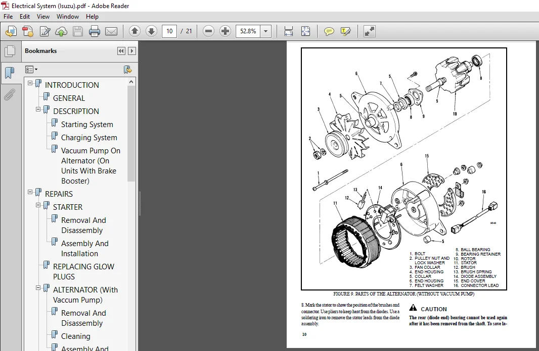
- GENERAL This section has a description and the repair procedures for the alternator with a voltage regulator as part of the alternator. CAUTION When using an arc welder, always disconnect the ground lead from the lift truck battery to prevent alternator or battery damage. Attach the welding ground clamp as close to the weld area as possible to prevent welding current from damaging the bearings. The diodes and resistors in the electrical system can be damaged if the following cautions are not followed: • Do not disconnect the battery when the engine is running. The voltage surge can damage the diodes and resistors in the electrical system.
- • Do not disconnect an electric wire before the engine is stopped and the switches are “OFF”. • Do not cause a short–circuit by connecting the electric wires to the wrong terminals. Make sure a correct identification is made of the wire before it is connected. • Make sure a battery is the correct voltage and polarity before it is connected. • Do not check for current flow by making a spark because the electronic components can be damaged
- . NOTE: Information on alternators manufactured outside the United States is in the SRM (service repair manual) sections for lift trucks that use those alternators. DESCRIPTION (See FIGURE 1. and FIGURE 2.) NOTE: For this SRM section, the alternators are in two groups, Type A and Type B. The two types are very similar, but the Type A alternators have a set of three diodes (diode set) as well as the diode bridge. The Type B alternator has zener diodes as part of the diodes in the diode bridge.
- This alternator does not have a diode set, but does have an additional fan inside the rear housing. The basic operation of both types is very similar. The alternator generates an alternating current when the engine is running. The alternator is either ON or OFF. The alternator generates maximum current when it is ON and no current when it is OFF. The regulator switches the alternator between ON and OFF to get the average current needed to charge the battery.
- Alternator output is directly changed by engine speed and rotor field current. The alternating current is changed to a direct current by the diode bridge inside the alternator.
Table of Contents:
Hyster Forklift S40 60XL service manual
INTRODUCTION.........................................................................................................  1
	GENERAL..........................................................................................................  1
	DESCRIPTION......................................................................................................  1
REPAIRS..............................................................................................................  3
	GENERAL..........................................................................................................  3
	REMOVAL AND DISASSEMBLY (Type A).................................................................................  3
	CLEANING.........................................................................................................  3
	ASSEMBLY (Type A)................................................................................................  4
	REMOVAL AND DISAASSEMBLY (Type B)................................................................................  6
	CLEANING.........................................................................................................  8
	ASSEMBLY (Type B)................................................................................................  8
	INSTALLATION (Type A and Type B).................................................................................  9
CHECKS AND ADJUSTMENTS...............................................................................................  9
	GENERAL..........................................................................................................  9
	CHECK THE ALTERNATOR FOR LOW OUTPUT (Type A or Type B)........................................................... 10
	CHECK THE ALTERNATOR FOR HIGH OUTPUT (Type A or Type B).......................................................... 11
	CHECK THE CIRCUIT FOR THE BRUSHES................................................................................ 13
		Delco Alternators............................................................................................ 13
		Motorola Alternators......................................................................................... 13
	CHECK THE DIODES................................................................................................. 13
	CHECK THE DIODE BRIDGE........................................................................................... 13
		Delco and Leece–Neville Alternators.......................................................................... 13
		Motorola Alternators......................................................................................... 13
	CHECK THE FIELD WINDING FOR THE ROTOR............................................................................ 14
	CHECK THE WINDINGS IN THE STATOR................................................................................. 14
	CHECK THE VOLTAGE REGULATOR...................................................................................... 15
TROUBLESHOOTING...................................................................................................... 15
INTRODUCTION......................................................................................................... 16
	GENERAL.......................................................................................................... 16
	DESCRIPTION AND OPERATION........................................................................................ 16
		Service and Parking Brakes................................................................................... 18
REPAIRS.............................................................................................................. 18
	REMOVAL AND DISASSEMBLY.......................................................................................... 18
		Service and Parking Brakes................................................................................... 18
		Master Cylinder.............................................................................................. 19
	CLEANING AND INSPECTION.......................................................................................... 20
	ASSEMBLY AND INSTALLATION........................................................................................ 20
		Service and Parking Brakes................................................................................... 20
		Master Cylinder.............................................................................................. 25
CHECKS AND ADJUSTMENTS............................................................................................... 25
	ADJUST THE SERVICE BRAKES........................................................................................ 25
	ADJUST THE PARKING BRAKE......................................................................................... 26
		Units with Monotrol Pedal.................................................................................... 26
	REMOVE THE AIR FROM THE BRAKE SYSTEM............................................................................. 27
	ADJUST THE BRAKE PEDAL AND INCHING PEDAL......................................................................... 27
	CHECK AND ADJUST THE NEUTRAL START SWITCH (Monotrol Control Only)................................................ 31
TROUBLESHOOTING...................................................................................................... 33
SPECIFICATIONS....................................................................................................... 34
INTRODUCTION......................................................................................................... 35
	GENERAL.......................................................................................................... 35
SERVICE BRAKES AND PARKING BRAKE..................................................................................... 35
	DESCRIPTION AND OPERATION........................................................................................ 35
		Service Brakes............................................................................................... 35
		Parking Brake................................................................................................ 36
	REMOVAL AND DISASSEMBLY OF THE 260 mm (10.25 in) SERVICE BRAKES.................................................. 36
		Parking Brake................................................................................................ 38
	CLEANING......................................................................................................... 39
	INSPECTION....................................................................................................... 39
	ASSEMBLY AND INSTALLATION OF THE 260 mm (10.25 in) SERVICE BRAKES................................................ 39
		Adjustments.................................................................................................. 42
		Parking Brake Installation................................................................................... 43
		Adjust The Parking Brake For Lift Trucks With 260 mm (10.25 in) Service Brakes............................... 43
	REMOVAL AND DISASSEMBLY OF THE 310 mm (12.20 in) SERVICE BRAKES.................................................. 45
		Parking Brake................................................................................................ 47
	CLEANING......................................................................................................... 48
	INSPECTION....................................................................................................... 48
	ASSEMBLY AND INSTALLATION OF THE 310 mm (12.20 in) SERVICE BRAKES................................................ 48
		Adjustments.................................................................................................. 50
		Parking brake................................................................................................ 51
		Adjust The Parking Brake For Lift Trucks With 310 mm (12.20 in) Service Brakes............................... 51
	MASTER CYLINDER.................................................................................................. 52
		Removal...................................................................................................... 52
		Repair....................................................................................................... 52
		Installation................................................................................................. 52
		Cleaning And Inspection...................................................................................... 54
	MASTER CYLINDER WITH BRAKE BOOSTER............................................................................... 56
		Operation.................................................................................................... 56
		Repair....................................................................................................... 56
CHECKS AND ADJUSTMENTS............................................................................................... 58
	ADJUST THE SERVICE BRAKES........................................................................................ 58
	TEST THE PARKING BRAKE SWITCH (MONOTROL PEDAL ONLY).............................................................. 58
	REMOVE THE AIR FROM THE BRAKE SYSTEM............................................................................. 59
	ADJUST THE INCHING/BRAKE PEDAL................................................................................... 59
	ADJUSTMENT OF THE NEUTRAL START SWITCH (LIFT TRUCKS WITH MONOTROL PEDAL)......................................... 64
	TEST THE NEUTRAL START SWITCH (MONOTROL PEDAL)................................................................... 64
		Test 1....................................................................................................... 64
		Test 2....................................................................................................... 65
TORQUE SPECIFICATIONS................................................................................................ 65
TROUBLESHOOTING...................................................................................................... 65
LIFT TRUCK WEIGHTS*.................................................................................................. 68
HYDRAULIC SYSTEM..................................................................................................... 68
ELECTRICAL SYSTEM.................................................................................................... 69
CAPACITIES........................................................................................................... 69
MAST SPEEDS (MAZDA Gasoline/LPG - A187*& B187* Units)................................................................ 70
MAST SPEEDS (ISUZU Diesel - A187*& B187* Units)...................................................................... 70
MAST SPEEDS (GM 4-153 Gasoline/LPG - A187*).......................................................................... 71
MAST SPEEDS (GM 4-181 Gasoline/LPG - B187*).......................................................................... 71
MAST CREEP SPEEDS.................................................................................................... 72
WHEELS AND TIRES..................................................................................................... 72
TRANSMISSION PRESSURES............................................................................................... 72
ENGINE SPECIFICATIONS................................................................................................ 73
ENGINE SPECIFICATIONS................................................................................................ 74
TORQUE SPECIFICATIONS................................................................................................ 75
TORQUE SPECIFICATIONS................................................................................................ 76
COOLING SYSTEM....................................................................................................... 77
	INTRODUCTION..................................................................................................... 77
	DESCRIPTION...................................................................................................... 77
	RADIATOR......................................................................................................... 77
	RADIATOR CAP..................................................................................................... 77
	THERMOSTAT....................................................................................................... 77
	WATER PUMP....................................................................................................... 78
	FAN AND FAN SHROUD............................................................................................... 78
REPAIRS.............................................................................................................. 78
	COOLING SYSTEM CHECKS............................................................................................ 78
		Exhaust Leaks................................................................................................ 78
	RADIATOR......................................................................................................... 78
		Checks....................................................................................................... 78
		Cleaning The Radiator........................................................................................ 78
		Drain The Cooling System..................................................................................... 80
		Fill The Cooling System...................................................................................... 80
	WATER PUMP....................................................................................................... 80
		Checks....................................................................................................... 80
	THERMOSTAT....................................................................................................... 81
		Checks....................................................................................................... 81
	FAN AND FAN SHROUD............................................................................................... 81
TROUBLESHOOTING...................................................................................................... 82
FIGURE 1. HYDRAULIC SCHEMATIC SYMBOLS................................................................................ 83
FIGURE 2. HYDRAULIC SYSTEM SCHEMATIC................................................................................. 84
FIGURE 3. TRANSMISSION SCHEMATIC..................................................................................... 86
FIGURE 4. INSTRUMENT PANEL ELECTRICAL DIAGRAM........................................................................ 87
FIGURE 5. GASOLINE/LPG ENGINE WIRING DIAGRAM, MAZDA ENGINE, (G and LPS Rating)....................................... 88
FIGURE 6. GASOLINE/LPG ENGINE WIRING DIAGRAM, MAZDA ENGINE, (GS and LPS Rating)...................................... 90
FIGURE 7. GASOLINE/LPG CABLE DIAGRAM, MAZDA ENGINE, (G and LPG Rating)............................................... 92
FIGURE 8. GASOLINE/LPG ENGINE WIRING DIAGRAM, GM ENGINE(G and LPG Rating/GS and LPS Rating).......................... 94
FIGURE 9. GASOLINE/LPG ENGINE CABLE DIAGRMGM ENGINE,................................................................. 96
FIGURE 10. DIESEL ENGINE WIRING DIAGRAM ISUZU ENGINE (D Rating)...................................................... 98
FIGURE 11. DIESEL ENGINE WIRING DIAGRAM ISUZU ENGINE (DS Rating).....................................................100
FIGURE 12. DIESEL ENGINE CABLE DIAGRAM, ISUZU ENGINE.................................................................102
FIGURE 1. HYDRAULIC SYSTEM SCHEMATIC.................................................................................105
FIGURE 2. TRANSMISSION SCHEMATIC.....................................................................................106
FIGURE 3. WIRE SCHEMATIC, GM 4-181 ENGINE, GASOLINE AND LPG (1 OF 2).................................................107
FIGURE 4. WIRE SCHEMATIC, MAZDA 4-121G ENGINE, GASOLINE AND LPG......................................................111
FIGURE 5. WIRE SCHEMATIC, ISUZU DIESEL ENGINE (1OF 2 )...............................................................113
FIGURE 6. ELECTRICAL DIAGRAM, INSTRUMENT PANEL.......................................................................115
FIGURE 7. MAZDA ENGINE, GASOLINE/LPG CABLE DIAGRAM (G and LPG Rating)................................................117
FIGURE 8. MAZDA ENGINE, GASOLINE/LPG CABLE DIAGRAM (GS and LPS Rating)...............................................119
FIGURE 9. DIESEL ENGINE CABLE DIAGRAM (D Rating).....................................................................121
FIGURE 10. DIESEL ENGINE CABLE DIAGRAM (DS Rating)...................................................................123
FIGURE 11. GM ENGINE, GASOLINE/LPG CABLE DIAGRAM (G and LPG Rating)..................................................125
FIGURE 12. GM ENGINE, GASOLINE/LPG CABLE DIAGRAM (GS and LPS Rating).................................................127
INTRODUCTION.........................................................................................................129
	GENERAL..........................................................................................................129
	DESCRIPTION......................................................................................................129
REPAIRS..............................................................................................................130
	REMOVAL..........................................................................................................130
	CLEANING.........................................................................................................130
	INSPECTION.......................................................................................................130
	ASSEMBLY.........................................................................................................130
TROUBLESHOOTING......................................................................................................133
SPECIFICATIONS.......................................................................................................133
INTRODUCTION.........................................................................................................134
	GENERAL..........................................................................................................134
	DESCRIPTION......................................................................................................134
		Starting System..............................................................................................134
		Charging System..............................................................................................134
		Vacuum Pump On Alternator (On Units With Brake Booster)......................................................136
REPAIRS..............................................................................................................137
	STARTER..........................................................................................................137
		Removal And Disassembly......................................................................................137
		Assembly And Installation....................................................................................137
	REPLACING GLOW PLUGS.............................................................................................139
	ALTERNATOR (With Vaccum Pump)....................................................................................139
		Removal And Disassembly......................................................................................139
		Cleaning.....................................................................................................141
		Assembly And Installation....................................................................................141
	ALTERNATOR (Without Vacuum Pump).................................................................................142
		Removal And Disassembly......................................................................................142
		Cleaning.....................................................................................................144
		Assembly And Installation....................................................................................144
	REGULATOR REPLACEMENT............................................................................................145
CHECKS...............................................................................................................145
	GENERAL..........................................................................................................145
	STARTER..........................................................................................................145
		Starter Operation............................................................................................145
		Solenoid Coil Checks.........................................................................................146
		Brush Length.................................................................................................146
		Brush Holder.................................................................................................146
		Armature.....................................................................................................146
		Field Windings...............................................................................................147
		Clutch And Bearings..........................................................................................147
	COLD START AID...................................................................................................147
		Glow Plugs...................................................................................................147
		Resistor.....................................................................................................147
	CHARGING CIRCUIT.................................................................................................147
		Check For Low Output.........................................................................................147
		Check Ford High Output.......................................................................................149
	ALTERNATOR.......................................................................................................149
		Rotor Resistance.............................................................................................149
		Diodes Circuit...............................................................................................149
		Rotor Coil...................................................................................................150
		Stator Coil..................................................................................................150
		Diode Assembly...............................................................................................150
		Brushes And Bearings.........................................................................................151
	REGULATOR (At Hydraulic Tank)....................................................................................151
TROUBLESHOOTING......................................................................................................152
INTRODUCTION.........................................................................................................155
	GENERAL..........................................................................................................155
	DESCRIPTION......................................................................................................155
		Starting System..............................................................................................155
		Ignition System..............................................................................................155
		Charging System..............................................................................................156
REPAIR...............................................................................................................158
	STARTER..........................................................................................................158
		Removal And Disassembly......................................................................................158
		Assembly And Installation....................................................................................158
	BALLAST RESISTOR RELAY (Earlier Production)......................................................................160
	DISTRIBUTOR (Earlier Production With Contact Points).............................................................160
		Removal And Disassembly......................................................................................160
		Assembly And Installation....................................................................................162
	COIL REPLACEMENT.................................................................................................162
	DISTRIBUTOR (Later Production with Electronic Ignition System)...................................................162
		Removal And Disassembly......................................................................................162
		Assembly And Installation....................................................................................164
	ALTERNATOR (All Models)..........................................................................................164
		Removal And Disassembly......................................................................................164
		Assembly And Installation....................................................................................165
	REGULATOR REPLACEMENT (Earlier Production).......................................................................166
CHECKS AND ADJUSTMENTS...............................................................................................167
	GENERAL..........................................................................................................167
	STARTER..........................................................................................................167
		Check Operation..............................................................................................167
		Check Brush Length...........................................................................................168
		Check Brush Holder...........................................................................................168
		Armature.....................................................................................................168
		Field Windings...............................................................................................168
		Clutch And Bearing...........................................................................................168
	BALLAST RESISTOR RELAY (Earlier Production)......................................................................168
	DISTRIBUTOR......................................................................................................169
		Distributor Contact Clearance................................................................................169
	SPARK PLUGS......................................................................................................170
	COIL AND BALLAST RESISTOR (Earlier Production)...................................................................170
	ALTERNATOR.......................................................................................................170
		Check For Low Output (Alternator With Separate Regulator)....................................................170
		Check For Low Output (Alternator With Integral Regulator)....................................................172
		Check For High Output (Alternator With Separate Regulator)...................................................173
		Check For High Output (Alternator With Integral Regulator)...................................................173
		Rotor Resistance (Alternator with Separate Regulator)........................................................173
		Diodes Circuit (Alternator with Separate Regulator)..........................................................174
		Diode Assembly (Alternator With Separate Regulator)..........................................................174
		Check The Diodes, Diode Trio (Alternator with Integral Regulator)............................................174
		Check The Rectifier Bridge (Alternator with Integral Regulator)..............................................175
		Check Field Winding For The Rotor (All Alternators)..........................................................175
		Check Windings In The Stator (All Alternators)...............................................................176
		Brushes And Bearings.........................................................................................176
		Check The Voltage Regulator (Alternator with Separate Regulator).............................................176
		Check The Voltage Regulator (Alternator with Integral Regulator).............................................177
	ADJUSTMENTS......................................................................................................177
TROBLESHOOTING.......................................................................................................178
INTRODUCTION.........................................................................................................180
	GENERAL..........................................................................................................180
REPAIRS..............................................................................................................180
	FORKS............................................................................................................180
	CARRIAGE.........................................................................................................180
		Removal......................................................................................................180
	SAFETY PROCEDURES WHEN WORKING NEAR THE MAST.....................................................................181
		Installation.................................................................................................182
	MAST.............................................................................................................183
		Removal......................................................................................................183
		Disassembly..................................................................................................184
		Cleaning.....................................................................................................187
		Inspection, Forks, Mast, And Lift Chains.....................................................................187
		Assembly, Mast Components....................................................................................188
		Installation.................................................................................................189
CHECKS AND ADJUSTMENTS...............................................................................................190
	CHECK FOR LEAKS IN THE LIFT SYSTEM...............................................................................190
		Check the Lift Cylinders for Leaks...........................................................................190
		Check The Tilt Cylinders For Leaks...........................................................................190
	ADJUST THE TILT CYLINDER STROKE AND BACKWARD TILT ANGLE..........................................................190
	LIFT CHAIN ADJUSTMENTS...........................................................................................191
	MAST ADJUSTMENTS.................................................................................................191
	CARRIAGE ADJUSTMENTS.............................................................................................193
TROUBLESHOOTING......................................................................................................194
INTRODUCTION.........................................................................................................195
	GENERAL..........................................................................................................195
	DESCRIPTION......................................................................................................195
REPAIRS..............................................................................................................195
	COUNTERWEIGHT....................................................................................................196
		Removal......................................................................................................196
		Installation.................................................................................................196
	MUFFLER..........................................................................................................197
	HOOD.............................................................................................................197
		Removal......................................................................................................197
		Installation.................................................................................................197
	OVERHEAD GUARD...................................................................................................198
		Removal and Installation.....................................................................................198
	RADIATOR AND COOLANG SYSTEM......................................................................................198
		Removal......................................................................................................198
		Installation.................................................................................................198
	OPERATOR RESTRAINT SYSTEM........................................................................................198
	ENGINE REMOVAL AND INSTALLATION..................................................................................199
		Removal of the Engine and Transmission.......................................................................199
		Installation of the Engine and Transmission..................................................................202
	FUEL AND HYDRAULIC TANKS.........................................................................................204
		Inspection...................................................................................................204
		Repairs, Small Leaks.........................................................................................204
		Repairs, Large Leaks.........................................................................................204
		Cleaning.....................................................................................................204
		Steam Method of Cleaning.....................................................................................204
		Chemical Solution Method of Cleaning.........................................................................204
		Other Methods Of Preparation For Repair......................................................................205
	SAFETY LABELS....................................................................................................205
THE CARBURETOR, (MAZDA M4-121G ENGINE)...............................................................................209
	DESCRIPTION......................................................................................................209
	REPAIRS, CARBURETOR..............................................................................................210
		Removal......................................................................................................210
		Cleaning.....................................................................................................213
		Inspection...................................................................................................213
		Assembly.....................................................................................................213
		Installation.................................................................................................215
	CHECKS AND ADJUSTMENTS...........................................................................................215
		Carburetor, Idle Speed And Mixture Adjustment................................................................215
		Adjust The Governor..........................................................................................216
	ADJUST THE THROTTLE LINKAGE......................................................................................217
SPECIFICATIONS.......................................................................................................217
TROUBLESHOOTING......................................................................................................218
INTRODUCTION ........................................................................................................220
	GENERAL .........................................................................................................220
SAFETY PROCEDURES WHEN WORKING NEAR THE MAST ........................................................................220
REPAIRS .............................................................................................................221
	FORKS ...........................................................................................................221
		Removal .....................................................................................................221
		Installation ................................................................................................222
	CARRIAGES .......................................................................................................222
		Removal, Standard Carriage ..................................................................................222
		Removal, Side–Shift Carriage ................................................................................223
		Repairs .....................................................................................................223
		Installation, Standard Carriage .............................................................................223
		Installation, Side–Shift Carriage ...........................................................................224
	MAST ............................................................................................................225
		Removal .....................................................................................................225
		Disassembly, Three–Stage FFL Mast ...........................................................................231
		Disassembly, Two–Stage LFL And Two–Stage FFL Masts ..........................................................225
		Cleaning and Inspection .....................................................................................231
		Assembly, Two–Stage LFL And Two–Stage FFL Mast ..............................................................234
		Assembly, Three–Stage FFL Mast ..............................................................................235
		Installation, Mast ..........................................................................................236
	LIFT CYLINDERS ..................................................................................................237
		Removal, Main Lift Cylinders ................................................................................237
		Removal, Free–Lift Cylinder .................................................................................237
		Disassembly, Lift Cylinders .................................................................................237
		Assembly, Lift Cylinders ....................................................................................238
		Installation, Main Lift Cylinders ...........................................................................239
		Installation, Free–Lift Cylinder ............................................................................240
	HEADER HOSE ARRANGEMENTS H/S/E/J2.00–3.20XM (H/S/E/J40–65XM) S/E/J2.00–3.00XL (S/E/J40–60XL) ....................241
		New Hose Installation, Two–Stage, LFL Mast ..................................................................241
		Adjustment Of Hoses After Installation, Two–Stage LFL Mast ..................................................241
		New Hose Installation, Two–Stage FFL Mast ...................................................................245
		Adjustment Of Hoses After Installation, Two–Stage FFL Mast ..................................................245
		New Hose Installation, Three–Stage FFL Mast .................................................................249
		Adjustment Of Hoses After Installation, Three–Stage, FFL Mast ...............................................254
	HEADER HOSE ARRANGEMENTS H/E1.50–1.75XM, H/S2.00XMS (H/S/E25–35XM, H/S/E40XMS) and J1.60–2.00XMT (J30–40XMT) ....256
		New Hose Installation, Two–Stage LFL Mast ...................................................................257
		Adjustment Of Hoses After Installation, Two–Stage LFL Mast ..................................................257
		New Hose Installation, Two–Stage FFL Mast ...................................................................260
		Adjustment Of Hoses After Installation, Two–Stage FFL Mast ..................................................260
		New Hose Installation, Three–Stage, FFL Mast ................................................................264
		Adjustment Of Hoses After Installation, Three–Stage, FFL Mast ...............................................269
CHECKS AND ADJUSTMENTS ..............................................................................................270
	 CHECK FOR LEAKS IN THE LIFT AND TILT SYSTEM ....................................................................270
		 Check The Lift Cylinders For Leaks .........................................................................270
		 Check The Tilt Cylinders For Leaks .........................................................................270
	 ADJUST THE TILT CYLINDERS ......................................................................................270
	 ADJUST THE LIFT CHAINS .........................................................................................271
	 ADJUST THE MAST ................................................................................................272
	 ADJUST THE CARRIAGE ............................................................................................273
TROUBLESHOOTING......................................................................................................274
INTRODUCTION.........................................................................................................275
	GENERAL..........................................................................................................275
	DESCRIPTION AND OPERATION........................................................................................275
		Carriages....................................................................................................275
		Mast Mounts..................................................................................................276
	TWO-STAGE MAST, LIMITED FREE-LIFT................................................................................277
		Description and Operation....................................................................................277
	TWO-STAGE MAST, FULL FREE-LIFT...................................................................................279
		Description..................................................................................................279
		Operation....................................................................................................279
	THREE-STAGE, FULL FREE-LIFT MAST.................................................................................281
		Description..................................................................................................281
		Operation....................................................................................................281
INTRODUCTION.........................................................................................................283
	GENERAL..........................................................................................................283
	DESCRIPTION......................................................................................................284
	REMOVAL AND INSTALLATION OF THE ENGINE...........................................................................284
	CYLINDER HEAD AND MECHANISM......................................................................................284
		Cylinder Head, Removal.......................................................................................284
		Cylinder Head, Disassembly...................................................................................285
		Cleaning And Inspection......................................................................................286
		Valve And Valve Seats........................................................................................287
		Studs For The Rocker Arms....................................................................................287
		Hydraulic Valve Lifters, Replacement.........................................................................287
		Hydraulic Valve Lifters, Cleaning And Inspection.............................................................288
		Cylinder Head, Assembly......................................................................................288
		Cylinder Head, Installation..................................................................................288
		Rocker Arm Cover, Installation...............................................................................289
	TIMING GEAR COVER................................................................................................290
		Removal......................................................................................................290
		Installation.................................................................................................290
	CAMSHAFT.........................................................................................................291
		Removal......................................................................................................291
		Inspection...................................................................................................292
		Camshaft Bearings, Removal...................................................................................292
		Camshaft Bearings, Installation..............................................................................292
	DISTRIBUTOR......................................................................................................293
		Removal......................................................................................................293
		Installation.................................................................................................293
	LUBRICATION SYSTEM...............................................................................................294
		Oil Sump, Removal............................................................................................294
		Oil Sump, Installation.......................................................................................294
		Oil Pump, Removal............................................................................................294
		Oil Pump, Disassembly and Repair.............................................................................294
		Oil Pump, Assembly...........................................................................................295
		Oil Pump, Installation.......................................................................................295
	PISTON AND CONNECTING ROD ASSEMBLIES.............................................................................295
		Connecting Rod Bearings, Replacement.........................................................................295
		Piston And Connecting Rod Assemblies, Removal................................................................296
		Disassembly..................................................................................................297
		Piston, Cleaning And Inspection..............................................................................297
		Cylinder Bores, Inspection And Repair........................................................................297
		Piston Rings.................................................................................................298
		Assembly.....................................................................................................299
		Piston And Connecting Rod Assemblies, Installation...........................................................299
	CRANKSHAFT.......................................................................................................300
		Main Bearings, Replacement...................................................................................300
		Oil Seal For The Rear Main Bearing, Replacement (GM 4-181 and 3.0L Only).....................................301
		Oil Seal For The Rear Main Bearing, Replacement (Engines That Have A Two-Piece Oil Seal).....................301
		Crankshaft, Removal..........................................................................................302
		Inspection and Repair........................................................................................303
		How To Check The Clearance Between The Main Bearings And Their Journals......................................303
		Installation.................................................................................................304
	FLYWHEEL AND FLYWHEEL HOUSING....................................................................................305
		Flywheel, Removal............................................................................................305
		Ring Gear, Replacement.......................................................................................306
		Flywheel, Installation.......................................................................................306
	COOLING SYSTEM...................................................................................................306
		Coolant Pump.................................................................................................306
		Fan Drive....................................................................................................307
		Viscous Fan Drive............................................................................................307
ENGINE SPECIFICATIONS................................................................................................308
	ENGINE DATA......................................................................................................308
	CYLINDER HEAD....................................................................................................308
	HYDRAULIC VALVE LIFTER...........................................................................................309
	CAMSHAFT.........................................................................................................309
	PISTONS..........................................................................................................309
	CYLINDER BORE....................................................................................................310
	CRANKSHAFT.......................................................................................................310
	CONNECTING RODS..................................................................................................310
	COOLING SYSTEM...................................................................................................311
	LUBRICATION SYSTEM...............................................................................................311
TORQUE SPECIFICATIONS................................................................................................311
HIGH ENERGY IGNITION (HEI)...........................................................................................314
	DESCRIPTION......................................................................................................314
REPAIRS..............................................................................................................316
	DISTRIBUTOR......................................................................................................316
		Removal......................................................................................................316
		Disassembly..................................................................................................316
		Assembly.....................................................................................................321
	INSTALLATION, IF THE CRANKSHAFT WAS NOT ROTATED WHEN DISTRIBUTOR WAS REMOVED.....................................322
	NSTALLATION, IF THE CRANKSHAFT WAS ROTATED WHEN THE DISTRIBUTOR WAS REMOVED......................................323
	IGNITION COIL....................................................................................................323
		Removal, Some 4 And 6 Cylinder Models........................................................................323
		Installation, Some 4 And 6 Cylinder Models...................................................................324
		Removal, V8, Some 4 And 6 Cylinder Models....................................................................324
		Installation, V8, Some 4 And 6 Cylinder Models...............................................................325
	ELECTRONIC MODULE................................................................................................326
		Removal......................................................................................................326
		Installation.................................................................................................326
	SENSING COIL.....................................................................................................327
		Removal......................................................................................................327
		Installation.................................................................................................327
	SPARK PLUGS......................................................................................................327
		Removal......................................................................................................327
		Installation.................................................................................................328
	CHECKS AND ADJUSTMENTS...........................................................................................328
		Visual Checks................................................................................................328
		Check The High Voltage Wires.................................................................................328
		Checking The Ignition Coil...................................................................................328
		Coil In Distributor Cap Design...............................................................................328
		Separate Coil Design.........................................................................................329
		Checking The Sensing Coil....................................................................................329
		Check The Electronic Module..................................................................................330
		Ignition Timing Adjustment...................................................................................330
		Ignition System, GM V8-366 (6-litre).........................................................................331
		Ignition Timing and Idle Speed Adjustment, GM V6-LPG (4.3-litre).............................................331
SPECIFICATIONS.......................................................................................................331
TROUBLESHOOTING......................................................................................................332
INTRODUCTION.........................................................................................................333
	GENERAL..........................................................................................................333
	DESCRIPTION......................................................................................................333
REPAIRS..............................................................................................................335
	REMOVAL AND DISASSEMBLY..........................................................................................335
	CLEANING.........................................................................................................335
	INSPECTION.......................................................................................................335
	ASSEMBLY AND INSTALLATION........................................................................................336
TROUBLESHOOTING......................................................................................................337
	GENERAL..........................................................................................................337
INTRODUCTION.........................................................................................................338
	GENERAL..........................................................................................................338
	DESCRIPTION......................................................................................................340
		Hydraulic System.............................................................................................340
		Gear Pump Assembly...........................................................................................340
		Flow Control Valve...........................................................................................341
		Relief Valve (Early Model)...................................................................................341
		Relief Valve (Later Model)...................................................................................341
	OPERATION........................................................................................................343
		Hydraulic System.............................................................................................343
		Gear Pump....................................................................................................343
		Flow Control Valve...........................................................................................343
		Relief Valve (Early Model)...................................................................................343
		Relief Valve (Later Model)...................................................................................343
REPAIR...............................................................................................................345
	GEAR PUMP ASSEMBLY...............................................................................................345
		Removal and Disassembly......................................................................................345
		Assembly and Installation....................................................................................346
CHECKS AND ADJUSTMENTS...............................................................................................346
	CHECK AND ADJUST STEERING RELIEF PRESSURE........................................................................346
	CHECK GEAR PUMP FOR CORRECT FLOW.................................................................................347
TROUBLESHOOTING......................................................................................................347
INTRODUCTION.........................................................................................................349
	GENERAL..........................................................................................................349
DESCRIPTION..........................................................................................................349
	GENERAL..........................................................................................................349
	STEERING COLUMN GAUGES, METERS AND INDICATORS....................................................................352
	LED DISPLAY PANEL................................................................................................352
		Battery Discharge Indicators.................................................................................352
		Brush Wear Indicators........................................................................................353
		Motor Temperature Indicators.................................................................................354
	"LX" SERIES DISPLAY PANEL........................................................................................355
		Hourmeter Functions..........................................................................................356
		Battery Indicator Function...................................................................................356
		Status Code Function.........................................................................................356
	"ZX" SERIES DISPLAY PANELS.......................................................................................356
		Display Panel................................................................................................357
		Basic Display Panels.........................................................................................357
		Performance Display..........................................................................................359
		Brush Wear Indicators........................................................................................362
CHECKS AND ADJUSTMENTS...............................................................................................362
	GENERAL..........................................................................................................362
REPLACEMENT..........................................................................................................363
	GENERAL..........................................................................................................363
	METER REPLACEMENT................................................................................................363
	SENDER REPLACEMENT...............................................................................................364
		Fuel Level Sender............................................................................................364
		Pressure And Temperature Sender..............................................................................364
	I.T.W. DISPLAY PANEL.............................................................................................365
		Removal......................................................................................................365
	DISPLAY PANELS FOR THE EV - 100/200ZX MOTOR CONTROLLERS, COLUMN MOUNT............................................366
		Removal......................................................................................................366
		Replacing Display Panel Assembly.............................................................................366
		Indicator LEDs...............................................................................................366
		Battery Indicators...........................................................................................366
		Digital Display (Performance Disply Panel Only)..............................................................366
		Status Code Or Performance Level Switches And Indicator LEDs (Performance Display Panel Only)................366
		Replacing Parts Of The Basic Display Panel...................................................................367
		Replacing Parts Of The Performance Display Panel.............................................................369
	DISPLAY PANELS FOR THE EV-100/200ZX MOTOR CONTROLLERS, DASH MOUNT................................................369
		Removal And Replacement......................................................................................369
SPECIFICATIONS.......................................................................................................370
TROUBLESHOOTING......................................................................................................371
INTRODUCTION ........................................................................................................372
	GENERAL .........................................................................................................372
	DESCRIPTION .....................................................................................................372
	FUEL SYSTEM .....................................................................................................373
		Description .................................................................................................373
		Operation, Fuel Injection Pump, Model VE ....................................................................375
		Operation, Fuel Injection Pump, Model PE4A ..................................................................376
		Pneumatic Governor For Fuel Injection Pump, Model PE4A ......................................................377
		Inlet Manifold For Fuel Injection Pump, Model PE4A ..........................................................378
REPAIRS .............................................................................................................379
	FUEL INJECTION PUMP (ALL MODELS) ................................................................................379
		Removal .....................................................................................................379
		Installation ................................................................................................379
	REMOVAL AND INSTALLATION OF THE ENGINE ..........................................................................379
	CYLINDER HEAD AND VALVE MECHANISM ...............................................................................379
		Cylinder Head, Removal ......................................................................................379
		Valve Guides, Replacement ...................................................................................380
		Cylinder Head, Inspection And Repair ........................................................................381
		Combustion Chamber Plugs, Inspection And Repair .............................................................381
		Combustion Chamber Plugs, Installation ......................................................................381
		Valves, Inspection And Repair ...............................................................................382
		Valve Seat, Inspection ......................................................................................382
		Valve Seat, Removal .........................................................................................383
		Valve Seat, Installation ....................................................................................383
		Valve Spring, Inspection ....................................................................................383
		Rocker Arms, Inspection And Assembly ........................................................................383
		Installation Of The Cylinder Head ...........................................................................384
	TIMING GEAR CASE ................................................................................................385
		Removal .....................................................................................................385
		Installation ................................................................................................385
	CAMSHAFT ........................................................................................................387
		Removal .....................................................................................................387
		Inspection ..................................................................................................387
		Camshaft Bearings ...........................................................................................388
		Cam Followers ...............................................................................................388
	CAMSHAFT, INSTALLATION ..........................................................................................388
	CRANKSHAFT AND MAIN BEARINGS ....................................................................................389
		Crankshaft, Removal .........................................................................................389
		Crankshaft, Inspection And Repair ...........................................................................389
		Main Bearings ...............................................................................................389
		Pilot Bearing ...............................................................................................390
		Crankshaft, Installation ....................................................................................390
	FLYWHEEL AND RING GEAR, H2.00–3.20XM (H40–65XM) .................................................................392
		Flywheel, Removal ...........................................................................................392
		Ring Gear, Replacement ......................................................................................392
		Flywheel, Installation ......................................................................................392
	PISTONS AND CONNECTING RODS .....................................................................................393
		Pistons And Connecting Rods, Removal ........................................................................393
		Disassembly .................................................................................................393
		Pistons, Inspection And Repair ..............................................................................394
		Piston Rings, Inspection And Repair .........................................................................394
		Piston Pins, Inspection And Repair ..........................................................................395
		Connecting Rods, Inspection And Repair ......................................................................396
		Pistons And Connecting Rods, Assembly And Installation ......................................................396
	CYLINDER BLOCK AND CYLINDER LINERS ..............................................................................396
		Cylinder Liners, Inspection .................................................................................396
		Replacement Of A Cylinder Liner .............................................................................397
	LUBRICATION SYSTEM ..............................................................................................398
		Oil Pump, Removal And Disassembly ...........................................................................398
		Oil Pump, Inspection ........................................................................................398
		Oil Pump, Assembly And Installation .........................................................................399
		Oil Filter ..................................................................................................399
	COOLING SYSTEM ..................................................................................................400
		Coolant Pump, Removal .......................................................................................400
		Coolant Pump, Disassembly ...................................................................................400
		Coolant Pump, Assembly And Installation .....................................................................400
		Thermostat, Replacement .....................................................................................401
CHECKS AND ADJUSTMENTS ..............................................................................................401
	VALVE CLEARANCE ADJUSTMENT ......................................................................................401
	CHECK THE TIMING OF THE FUEL INJECTION PUMP, MODEL VE ...........................................................402
	CHECK THE TIMING OF THE FUEL INJECTION PUMP, MODEL PE4A .........................................................403
	FUEL INJECTORS ..................................................................................................403
		Fuel Injectors, Removal .....................................................................................404
		Fuel Injectors, Inspection ..................................................................................404
		Fuel Injectors, Installation ................................................................................405
	DIESEL FUEL FILTERS .............................................................................................405
		Filter Replacement, Models With A Water Separator ...........................................................405
		Filter Replacement, Models Without A Water Separator ........................................................406
		Filter For The Fuel Injection Pump, Model PE4A ..............................................................406
	REMOVE AIR FROM THE FUEL SYSTEM .................................................................................406
		Throttle Linkage, Adjustment ................................................................................407
		Idle Speed, Adjustment ......................................................................................407
		Check The Elements For The Cold Start Aid System ............................................................407
ENGINE SPECIFICATIONS ...............................................................................................407
TORQUE SPECIFICATIONS ...............................................................................................409
SAFETY PROCEDURES WHEN WORKING NEAR THE MAST.........................................................................410
	SAFETY PROCEDURES WHEN WORKING NEAR THE MAST.....................................................................410
LIFT CYLINDERS.......................................................................................................413
	GENERAL..........................................................................................................413
	DESCRIPTION......................................................................................................413
		Lowering Control Valve.......................................................................................413
		Cylinders (General)..........................................................................................416
		Cylinders (H520-620B,H700-800A)..............................................................................418
		Cylinders (H360-460B)........................................................................................419
		Cylinders (Two-Speed)........................................................................................419
REPAIRS..............................................................................................................420
	REMOVAL OF THE LIFT CYLINDER WITHOUT REMOVING THE MAST...........................................................420
		Standard Masts with the Main Lift Cylinder Fastened to the Crossmember of the Inner Mast.....................420
		Standard and Full Free-Lift Masts with the Lift Cylinder to a Crosshead......................................424
		Masts that have Two Cylinders, A Main Lift Cylinder  and a Free-Lift Cylinder................................422
	DISASSEMBLY......................................................................................................422
	ASSEMBLY.........................................................................................................424
	INSTALLATION OF THE LIFT CYLINDER IN THE MAST....................................................................424
		Standard Masts with the Main Lift Cylinder Fastened to the Crossmember of the Inner Mast.....................424
		Standard and Full-Free-Lift Masts with the Lift Cylinder Fastened to a Crosshead.............................424
	CHEVRON PACKING..................................................................................................425
LIFT CYLINDERS FOR VISTA MASTS.......................................................................................428
	DESCRIPTION......................................................................................................428
		Lowering Control Valve.......................................................................................430
	REMOVAL..........................................................................................................431
	DISASSEMBLY......................................................................................................431
	ASSEMBLY.........................................................................................................431
	INSTALLATION.....................................................................................................432
		Main Lift Cylinders..........................................................................................432
		Free-Lift Cylinders..........................................................................................432
CHECKS AND ADJUSTMENTS...............................................................................................433
	CHECK FOR LEAKS IN LIFT SYSTEM...................................................................................433
TROUBLESHOOTING......................................................................................................434
SPECIFICATIONS.......................................................................................................435
THE LPG FUEL SYSTEM (IMPCO CA 50, CA 100)............................................................................436
	GENERAL..........................................................................................................436
	DESCRIPTION......................................................................................................436
		Fuel Tank....................................................................................................437
		Fuel Filter And Fuel Valve Unit..............................................................................438
		Vaporizer....................................................................................................438
		The IMPCO CA 100 Carbureto...................................................................................440
		IMPCO CA 50 Carburetor.......................................................................................442
		The Governor (GM Engines Only)...............................................................................443
		Governor With Electronic Controller..........................................................................444
REPAIRS..............................................................................................................445
	LPG TANK.........................................................................................................445
		Removal......................................................................................................445
		Installation.................................................................................................446
	REPLACE THE HOSES................................................................................................446
	HYDROSTATIC RELIEF VALVE.........................................................................................446
		Removal and Installation.....................................................................................446
	FILTER UNIT......................................................................................................447
		Replacement Of the Fuel Filter Element.......................................................................447
		Replacement of the Diaphragm and Fuel Valve..................................................................448
	VAPORIZER........................................................................................................448
		Removal......................................................................................................448
		Disassembly..................................................................................................448
		Cleaning.....................................................................................................448
		Inspection...................................................................................................448
		Assembly.....................................................................................................450
		Installation.................................................................................................450
	CARBURETOR (IMPCO CA 100)........................................................................................452
		Removal......................................................................................................452
		Disassembly..................................................................................................452
		Cleaning.....................................................................................................452
		Assembly.....................................................................................................452
		Installation.................................................................................................455
	CARBURETER (IMPCO CA 50).........................................................................................454
		Removal......................................................................................................454
		Disassembly..................................................................................................454
		Cleaning.....................................................................................................455
		Inspection...................................................................................................455
		Assembly (See FIGURE 26.)....................................................................................455
		Installation.................................................................................................455
CHECKS AND ADJUSTMENTS...............................................................................................456
	CHECK THE FILTER UNIT............................................................................................456
	CHECK THE VAPORIZER..............................................................................................456
		Pressure Reducer Valve.......................................................................................456
		Vapor Valve..................................................................................................456
	ADJUST THE CARBURETOR............................................................................................456
		Idle Mixture.................................................................................................456
		Idle Speed...................................................................................................456
		Power Mixture................................................................................................456
	ADJUST THE GOVERNOR (GM Engines Only)............................................................................457
		Checks.......................................................................................................457
		Main Adjusting Screw.........................................................................................457
		Secondary Adjusting Screw....................................................................................457
		AISAN Governor...............................................................................................458
		Adjustment, AISAN Governor...................................................................................458
TROUBLESHOOTING......................................................................................................459
INTRODUCTION.........................................................................................................463
	GENERAL..........................................................................................................463
	DESCRIPTION......................................................................................................463
	OPERATION........................................................................................................464
		Lift Section.................................................................................................465
		Tilt Section.................................................................................................465
		Relief Valve.................................................................................................467
	SOLENOID VALVE FOR AUXILIARY FUNCTION............................................................................468
		Operation....................................................................................................468
REPAIRS..............................................................................................................468
	MAIN CONTROL VALVE...............................................................................................468
		Removal and Disassembly......................................................................................468
		Cleaning and Inspection......................................................................................469
		Assembly.....................................................................................................469
		Installation.................................................................................................469
	SOLENOID VALVE FOR AUXILIARY FUNCTION............................................................................469
		Removal and Disassembly......................................................................................469
		Assembly and Installation....................................................................................471
CHECKS AND ADJUSTMENTS...............................................................................................471
	PRESSURE RELIEF VALVES...........................................................................................471
		Primary Relief Valve.........................................................................................471
		Seconday Relief Valve........................................................................................472
	CONTROL LEVER ARRANGEMENT........................................................................................472
TROUBLESHOOTING......................................................................................................475
SPECIFICATIONS.......................................................................................................477
MAZDA M4-121G ENGINE.................................................................................................478
	GENERAL..........................................................................................................478
	DESCRIPTION......................................................................................................479
	REMOVAL AND INSTALLATION OF THE ENGINE...........................................................................479
	CYLINDER HEAD AND VALVE MECHANISM................................................................................479
		Cylinder Head, Removal.......................................................................................479
		Cylinder Head, Inspection and Repairs........................................................................480
		Rocker Arm Assembly..........................................................................................480
		Valve Guides.................................................................................................480
		Valve Seats..................................................................................................481
		Valves.......................................................................................................481
		Valve Springs................................................................................................481
		Cylinder Head, Installation..................................................................................481
	TIMING GEAR CASE, REMOVAL........................................................................................482
	TIMING GEAR CASE, INSTALLATION...................................................................................483
	CAMSHAFT.........................................................................................................483
		Removal......................................................................................................483
		Inspection...................................................................................................484
		Cam Followers, Inspection....................................................................................484
		Installation.................................................................................................484
	CRANKSHAFT AND MAIN BEARINGS.....................................................................................484
		Crankshaft, Removal..........................................................................................484
		Crankshaft, Inspection And Repair............................................................................485
		Main Bearings................................................................................................486
		Crankshaft, Installation.....................................................................................486
	PISTONS AND CONNECTING RODS......................................................................................487
		Removal......................................................................................................487
		Disassembly..................................................................................................487
		Pistons, Inspection And Repair...............................................................................487
		Piston Rings.................................................................................................488
		Piston Pin and Bushing.......................................................................................488
		Connecting Rods and Bearings, Inspection.....................................................................488
		Pistons and Connecting Rods, Assembly........................................................................488
		Pistons and Connecting Rods, Installation....................................................................489
	CYLINDER BLOCK AND CYLINDER LINERS...............................................................................489
		Cylinder Block, Repairs......................................................................................489
		Cylinder Liners..............................................................................................489
	DISTRIBUTOR......................................................................................................490
		Removal......................................................................................................490
		Installation.................................................................................................490
	OIL PUMP.........................................................................................................492
		Removal......................................................................................................492
		Repairs......................................................................................................492
		Installation.................................................................................................493
	GOVERNOR.........................................................................................................493
		Description..................................................................................................493
		Removal......................................................................................................493
		Disassembly..................................................................................................494
		Assembly.....................................................................................................495
		Installation.................................................................................................496
	COOLANT PUMP.....................................................................................................496
		Removal......................................................................................................496
		Disassembly and Repair.......................................................................................497
		Assembly.....................................................................................................497
		Installation.................................................................................................498
	FLYWHEEL.........................................................................................................498
		Repairs......................................................................................................498
		Installation.................................................................................................498
CHECKS AND ADJUSTMENTS...............................................................................................498
	ADJUST THE VALVES................................................................................................498
	ADJUST THE THROTTLE LINKAGE......................................................................................499
ENGINE SPECIFICATIONS................................................................................................499
	ENGINE SPECIFICATIONS............................................................................................499
		Engine Data..................................................................................................499
		Cooling System...............................................................................................499
		Cylinder Head and Valve Mechanism............................................................................499
		Camshaft.....................................................................................................501
		Timing Gear..................................................................................................502
		Camshaft.....................................................................................................502
		Connecting Rods..............................................................................................502
		Cylinder Liners..............................................................................................502
		Pistons......................................................................................................502
		Lubrication System...........................................................................................503
		Fuel Pump....................................................................................................503
	TORQUE SPECIFICATIONS............................................................................................504
TROUBLESHOOTING......................................................................................................505
Please Note:
- This is the SAME exact manual used by your dealers to fix your vehicle.
- The same can be yours in the next 2-3 mins as you will be directed to the download page immediately after paying for the manual.
- Any queries / doubts regarding your purchase, please feel free to contact [email protected]