Hyster H177 Service Manual – PDF DOWNLOAD
Original price was: $89.95.$36.95Current price is: $36.95.
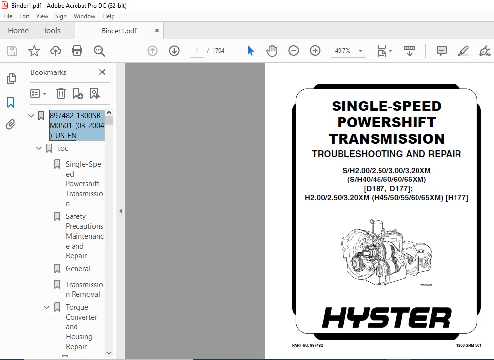
Hyster H177 Service Manual – PDF DOWNLOAD
PART NO. 897482
Description
Hyster H177 Service Manual – PDF DOWNLOAD
DESCRIPTION:
Hyster H177 Service Manual – PDF DOWNLOAD
PART NO. 897482
SAFETY PRECAUTIONS MAINTENANCE AND REPAIR :
• When lifting parts or assemblies, make sure all slings, chains, or cables are correctly
fastened, and that the load being lifted is balanced. Make sure the crane, cables, and
chains have the capacity to support the weight of the load.
• Do not lift heavy parts by hand, use a lifting mechanism.
• Wear safety glasses.
• DISCONNECT THE BATTERY CONNECTOR before doing any maintenance or repair
on electric lift trucks. Disconnect the battery ground cable on internal combustion lift
trucks.
• Always use correct blocks to prevent the unit from rolling or falling. See HOW TO PUT
THE LIFT TRUCK ON BLOCKS in the Operating Manual or the Periodic Maintenance
section.
• Keep the unit clean and the working area clean and orderly.
• Use the correct tools for the job.
• Keep the tools clean and in good condition.
• Always use HYSTER APPROVED parts when making repairs. Replacement parts
must meet or exceed the specifications of the original equipment manufacturer.
• Make sure all nuts, bolts, snap rings, and other fastening devices are removed before
using force to remove parts.
• Always fasten a DO NOT OPERATE tag to the controls of the unit whenmaking repairs,
or if the unit needs repairs.
• Be sure to follow the WARNING and CAUTION notes in the instructions.
• Gasoline, Liquid Petroleum Gas (LPG), Compressed Natural Gas (CNG), and Diesel fuel
are flammable. Be sure to follow the necessary safety precautions when handling these
fuels and when working on these fuel systems.
• Batteries generate flammable gas when they are being charged. Keep fire and sparks
away from the area. Make sure the area is well ventilated.
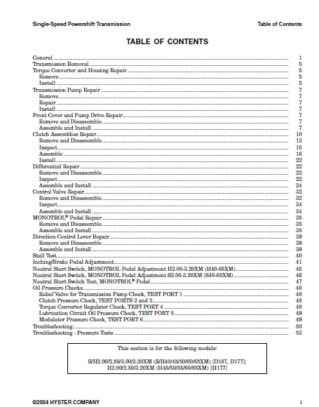
TABLE OF CONTENTS:
Hyster H177 Service Manual – PDF DOWNLOAD
897482-1300SRM0501-(03-2004)-US-EN...................................................... 1 toc................................................................................. 1 Single-Speed Powershift Transmission............................................ 1 Safety Precautions Maintenance and Repair....................................... 2 General......................................................................... 5 Transmission Removal............................................................ 9 Torque Converter and Housing Repair............................................. 9 Remove...................................................................... 9 Install..................................................................... 9 Transmission Pump Repair........................................................ 11 Remove...................................................................... 11 Repair...................................................................... 11 Install..................................................................... 11 Front Cover and Pump Drive Repair............................................... 11 Remove and Disassemble...................................................... 11 Assemble and Install........................................................ 11 Clutch Assemblies Repair........................................................ 14 Remove and Disassemble...................................................... 17 Inspect..................................................................... 19 Assemble.................................................................... 20 Install..................................................................... 26 Differential Repair............................................................. 26 Remove and Disassemble...................................................... 26 Inspect..................................................................... 26 Assemble and Install........................................................ 28 Control Valve Repair............................................................ 36 Remove and Disassemble...................................................... 36 Inspect..................................................................... 38 Assemble and Install........................................................ 38 MONOTROL® Pedal Repair.......................................................... 39 Remove and Disassemble...................................................... 39 Assemble and Install........................................................ 39 Direction Control Lever Repair.................................................. 43 Remove and Disassemble...................................................... 43 Assemble and Install........................................................ 43 Stall Test...................................................................... 44 Inching/Brake Pedal Adjustment.................................................. 45 Neutral Start Switch, MONOTROL Pedal Adjustment H2.00-3.20XM (H4................ 49 Neutral Start Switch, MONOTROL Pedal Adjustment S2.00-3.20XM (S4................ 50 Neutral Start Switch Test, MONOTROL® Pedal...................................... 51 Oil Pressure Checks............................................................. 52 Relief Valve for Transmission Pump Check, TEST PORT 1....................... 52 Clutch Pressure Check, TEST PORTS 2 and 3................................... 52 Torque Converter Regulator Check, TEST PORT 4............................... 52 Lubrication Circuit Oil Pressure Check, TEST PORT 5......................... 53 Modulator Pressure Check, TEST PORT 6....................................... 53 Troubleshooting................................................................. 54 Troubleshooting - Pressure Tests................................................ 57 tables.............................................................................. 1 Table 1. Adjustment of Shims for Pinion Assembly................................ 29 Table 2. Ring and Pinion Tooth Contact Adjustment............................... 30 Table 3. Stall Speeds........................................................... 45 Table 4. Transmission Oil Pressures Test Ports.................................. 53 897494-1900SRM0513-(06-2004)-US-EN...................................................... 61 toc................................................................................. 61 Hydraulic System................................................................ 61 Safety Precautions Maintenance and Repair....................................... 62 General......................................................................... 65 Description..................................................................... 65 Hydraulic System............................................................ 65 Gear Pump Assembly.......................................................... 65 Flow Control Valve.......................................................... 65 Relief Valve................................................................ 65 Operation....................................................................... 72 Hydraulic System............................................................ 72 Gear Pump................................................................... 72 Flow Control Valve.......................................................... 72 Relief Valve................................................................ 72 Gear Pump Assembly Repair....................................................... 74 Remove and Disassemble...................................................... 74 Assemble and Install........................................................ 75 Steering Relief Pressure Check and Adjustment................................... 75 Gear Pump Flow Check............................................................ 76 Troubleshooting................................................................. 76 897495-2200SRM0514-(01-2004)-US-EN Display.............................................. 81 toc................................................................................. 81 Instrument Cluster.............................................................. 81 Safety Precautions Maintenance and Repair....................................... 82 General......................................................................... 85 Description..................................................................... 85 Display Panels on Steering Column, Internal Combustion...................... 85 Display Panels on Steering Column, Electric Lift Trucks..................... 90 Standard Display Panel.................................................. 90 Enhanced Display Panel.................................................. 91 Curtis 1215 Display Panel................................................... 95 Description and Features................................................ 95 Operation............................................................... 95 Cluster-Type Display Panel (Internal Combustion) Replacement.................... 96 Remove and Disassemble...................................................... 96 Assemble and Install........................................................ 99 Cluster Display Panel (Electric Lift Truck) Replacement......................... 101 Display Panel Assembly, Replace............................................. 101 LED Indicators.............................................................. 101 Battery Indicators.......................................................... 102 Digital Display (Enhanced Display Panel Only)............................... 102 Status Code or Performance Level Switches and LED indicators (En............ 102 Standard Display Panel Parts, Replace....................................... 102 Enhanced Display Panel Parts, Replace....................................... 103 Curtis 1215 Display Panel Replacement........................................... 103 Remove...................................................................... 103 Install..................................................................... 103 tables.............................................................................. 81 Table 1. Instrument Cluster, Internal Combustion................................ 85 897495-2200SRM0514-(01-2004)-US-EN...................................................... 107 toc................................................................................. 107 Instrument Cluster.............................................................. 107 Safety Precautions Maintenance and Repair....................................... 108 General......................................................................... 111 Description..................................................................... 111 Display Panels on Steering Column, Internal Combustion...................... 111 Display Panels on Steering Column, Electric Lift Trucks..................... 116 Standard Display Panel.................................................. 116 Enhanced Display Panel.................................................. 117 Curtis 1215 Display Panel................................................... 121 Description and Features................................................ 121 Operation............................................................... 121 Cluster-Type Display Panel (Internal Combustion) Replacement.................... 122 Remove and Disassemble...................................................... 122 Assemble and Install........................................................ 125 Cluster Display Panel (Electric Lift Truck) Replacement......................... 127 Display Panel Assembly, Replace............................................. 127 LED Indicators.............................................................. 127 Battery Indicators.......................................................... 128 Digital Display (Enhanced Display Panel Only)............................... 128 Status Code or Performance Level Switches and LED indicators (En............ 128 Standard Display Panel Parts, Replace....................................... 128 Enhanced Display Panel Parts, Replace....................................... 129 Curtis 1215 Display Panel Replacement........................................... 129 Remove...................................................................... 129 Install..................................................................... 129 tables.............................................................................. 107 Table 1. Instrument Cluster, Internal Combustion................................ 111 897509-2200SRM0524-(02-2001)-US-EN...................................................... 133 toc................................................................................. 133 Electrical System............................................................... 133 Safety Precautions Maintenance and Repair....................................... 134 General......................................................................... 137 Description..................................................................... 137 Starting System............................................................. 137 Ignition System............................................................. 137 Charging System............................................................. 138 Starter Repair.................................................................. 139 Remove and Disassemble...................................................... 139 Assemble and Install........................................................ 139 Coil Replacement................................................................ 141 Distributor Repair H1.50-1.75XM, H2.00XMS (S/H25-35XM, S/H40XMS)................ 142 Remove and Disassemble...................................................... 142 Assemble and Install........................................................ 142 Distributor Repair S/H2.00-3.20XM (S/H40-65XM).................................. 144 Remove and Disassemble...................................................... 144 Assemble and Install........................................................ 146 Alternator Repair............................................................... 146 Remove and Disassemble...................................................... 146 Assemble and Install........................................................ 148 General Checks and Adjustments.................................................. 148 Starter Checks.................................................................. 148 Operation, Check............................................................ 148 Brush Holder, Check......................................................... 149 Armature, Check............................................................. 149 Field Windings, Check....................................................... 149 Clutch and Bearing, Check................................................... 150 Ignition System Check and Adjustment............................................ 150 Engine Timing, Adjust....................................................... 150 Spark Plugs, Check.......................................................... 151 Charging Circuit Checks......................................................... 151 Low Output, Check........................................................... 151 High Output, Check.......................................................... 152 Diodes, Check............................................................... 152 Rotor Field Winding, Check.................................................. 153 Stator Windings, Check...................................................... 153 Brushes and Bearings, Check................................................. 154 Voltage Regulator, Check.................................................... 154 Troubleshooting................................................................. 154 897844-2200SRM0603-(01-1996)-US-EN...................................................... 159 .................................................................................... 159 .................................................................................... 160 .................................................................................... 161 .................................................................................... 162 .................................................................................... 163 .................................................................................... 164 .................................................................................... 165 .................................................................................... 166 .................................................................................... 167 .................................................................................... 168 .................................................................................... 169 .................................................................................... 170 .................................................................................... 171 .................................................................................... 172 .................................................................................... 173 .................................................................................... 174 .................................................................................... 175 .................................................................................... 176 .................................................................................... 177 .................................................................................... 178 .................................................................................... 179 .................................................................................... 180 .................................................................................... 181 .................................................................................... 182 .................................................................................... 183 .................................................................................... 184 .................................................................................... 185 .................................................................................... 186 .................................................................................... 187 .................................................................................... 188 .................................................................................... 189 .................................................................................... 190 .................................................................................... 191 .................................................................................... 192 .................................................................................... 193 .................................................................................... 194 899784-2200SRM0002-(12-2004)-US-EN...................................................... 195 toc................................................................................. 195 Alternator with Regulator....................................................... 195 Safety Precautions Maintenance and Repair....................................... 196 General......................................................................... 199 Description..................................................................... 199 Alternator Repair............................................................... 201 Alternator Type A........................................................... 201 Remove and Disassemble.................................................. 201 Clean................................................................... 202 Assemble................................................................ 203 Install................................................................. 203 Alternator Type B........................................................... 206 Remove and Disassemble.................................................. 206 Clean................................................................... 206 Assemble................................................................ 207 Install................................................................. 208 General Check and Adjustment.................................................... 209 Low Output Check (Type A or Type B)............................................. 209 High Output Check (Type A or Type B)............................................ 211 Brushes Circuit Check........................................................... 212 Delco Alternators........................................................... 212 Motorola Alternators........................................................ 213 Diodes Check.................................................................... 214 Diode Bridge Check.............................................................. 214 Delco and Leece-Neville Alternators......................................... 214 Motorola Alternators........................................................ 214 Rotor Field Winding Check....................................................... 215 Stator Windings Check........................................................... 216 Voltage Regulator Check......................................................... 216 Troubleshooting................................................................. 216 1456975-0600SRM0706-(12-2004)-US-EN..................................................... 221 toc................................................................................. 221 Perkins Diesel Engines.......................................................... 221 Safety Precautions Maintenance and Repair....................................... 222 Description..................................................................... 229 General Safety Rules............................................................ 229 Engine Removal and Installation................................................. 230 General..................................................................... 230 Lifting Engine.............................................................. 230 Engine Identification........................................................... 230 General..................................................................... 230 Engine Data................................................................. 231 Cylinder Head Assembly Repair................................................... 232 Description................................................................. 232 Valve Cover................................................................. 232 Remove.................................................................. 232 Breather System, Clean and Replace...................................... 232 Install................................................................. 233 Rocker Assembly............................................................. 233 Remove.................................................................. 233 Disassemble............................................................. 234 Assemble................................................................ 234 Install................................................................. 234 Valve Clearance, Adjust................................................. 234 Valve Spring, Replace................................................... 235 Piston TDC.............................................................. 236 Cylinder Head............................................................... 236 Remove.................................................................. 236 Clean and Inspect....................................................... 238 Valve, Check............................................................ 238 Install................................................................. 238 Valves and Valve Springs.................................................... 240 Remove.................................................................. 240 Install................................................................. 240 Valve Guides................................................................ 241 Inspect................................................................. 241 Remove.................................................................. 241 Install................................................................. 241 Valve Seats, Repair..................................................... 242 Valve Seat Insert, Install.............................................. 242 Piston and Connecting Rod Assembly Repair....................................... 243 Description................................................................. 243 Connecting Rod Bearings, Replace............................................ 244 Piston and Connecting Rods.................................................. 245 Remove.................................................................. 245 Disassemble............................................................. 245 Inspect................................................................. 246 Replace................................................................. 246 Assemble................................................................ 246 Install................................................................. 247 Piston Rings................................................................ 248 Remove.................................................................. 248 Inspect................................................................. 248 Install................................................................. 249 Crankshaft Assembly Repair...................................................... 250 Description................................................................. 250 Crankshaft Pulley........................................................... 250 Remove.................................................................. 250 Install................................................................. 250 Rear Oil Seal............................................................... 250 Remove.................................................................. 250 Install................................................................. 251 Wear Sleeve, Install.................................................... 251 Thrust Washers.............................................................. 252 Crankshaft Axial Movement, Check........................................ 252 Remove.................................................................. 252 Install................................................................. 253 Main Bearings............................................................... 253 Remove.................................................................. 253 Install................................................................. 254 Crankshaft.................................................................. 254 Remove.................................................................. 254 Inspect................................................................. 255 Wear Sleeve, Install.................................................... 255 Install................................................................. 256 Front and Rear Bearing Cap Seals, Install................................... 257 Timing Case and Timing Gears Repair............................................. 258 Description................................................................. 258 Timing Case................................................................. 259 Remove.................................................................. 259 Replace................................................................. 259 Install................................................................. 260 Front Oil Seal.............................................................. 261 Remove.................................................................. 261 Install................................................................. 261 Idler Gear.................................................................. 262 Remove.................................................................. 262 Install................................................................. 262 Idler Gear Bushings, Replace................................................ 262 Idler Gear Hub.............................................................. 263 Remove.................................................................. 263 Install................................................................. 263 Camshaft Assembly, Fuel Injection Pump...................................... 264 Remove.................................................................. 264 Install................................................................. 264 Camshaft Assembly, Valves................................................... 265 Remove.................................................................. 265 Install................................................................. 266 Crankshaft Gear............................................................. 266 Remove.................................................................. 266 Install................................................................. 266 Timing Case Backplate....................................................... 266 Remove.................................................................. 266 Install................................................................. 267 Cylinder Block Assembly Repair.................................................. 267 Description................................................................. 267 Cylinder Block.............................................................. 267 Disassemble............................................................. 267 Inspect................................................................. 268 Cylinder Bore, Check.................................................... 268 Assemble................................................................ 268 Engine Timing................................................................... 269 Description................................................................. 269 Set Timing of Number One Piston to Top Dead Center (TDC).................... 270 Valve Timing, Check......................................................... 271 Fuel Pump Timing Check...................................................... 271 Lubrication System Repair....................................................... 273 Description................................................................. 273 Oil Filter, Replace......................................................... 273 Oil Sump.................................................................... 274 Remove.................................................................. 274 Install................................................................. 274 Oil Pump.................................................................... 275 Remove.................................................................. 275 Inspect................................................................. 275 Install................................................................. 276 Relief Valve................................................................ 276 Remove.................................................................. 276 Disassemble............................................................. 276 Inspect................................................................. 276 Assemble................................................................ 276 Install................................................................. 276 Fuel System Repair.............................................................. 277 Description................................................................. 277 Fuel Filter, Replace........................................................ 277 Fuel Injectors.............................................................. 278 Remove.................................................................. 278 Inspect................................................................. 278 Install................................................................. 278 Fuel Pump................................................................... 279 Remove.................................................................. 279 Disassemble............................................................. 279 Assemble................................................................ 280 Install................................................................. 280 Test.................................................................... 280 Water Separator............................................................. 281 Remove.................................................................. 281 Disassemble............................................................. 281 Assemble................................................................ 281 Install................................................................. 281 Fuel Injection Pump......................................................... 282 Remove.................................................................. 282 Install................................................................. 282 Fuel System Air Removal..................................................... 283 Governor Weight Assembly.................................................... 284 Remove.................................................................. 284 Install................................................................. 284 Engine Speed Control Assembly............................................... 284 Remove.................................................................. 284 Replace................................................................. 285 Install................................................................. 285 Fuel Injection Pump Linkage................................................. 286 Remove.................................................................. 286 Fuel Control Lever, Replace............................................. 286 Governor Control Lever, Replace......................................... 287 Install................................................................. 287 Record Maximum Fuel Position................................................ 288 Record Maximum Fuel Position of Fuel Rack............................... 288 Set Adjustment Screw for Maximum Fuel Setting........................... 290 Electrical Stop Solenoid.................................................... 291 Remove.................................................................. 291 Install................................................................. 291 Cooling System Repair........................................................... 291 Description................................................................. 291 Thermostat, Replace......................................................... 291 Coolant Pump................................................................ 292 Remove.................................................................. 292 Install................................................................. 292 Fan......................................................................... 292 Remove.................................................................. 292 Install................................................................. 292 Flywheel and Housing Repair..................................................... 293 Description................................................................. 293 Flywheel.................................................................... 293 Remove.................................................................. 293 Install................................................................. 293 Ring Gear, Replace.......................................................... 293 Flywheel Housing............................................................ 293 Remove.................................................................. 293 Install................................................................. 293 Electrical System Repair........................................................ 294 Drive Belt.................................................................. 294 Alternator.................................................................. 294 Remove.................................................................. 294 Install................................................................. 295 Starter Motor............................................................... 295 Remove.................................................................. 295 Install................................................................. 295 Glow Plugs.................................................................. 295 Remove.................................................................. 295 Continuity Check........................................................ 296 Operation Check......................................................... 296 Install................................................................. 296 Engine Specifications........................................................... 297 Cylinder Head Assembly...................................................... 297 Piston and Connecting Rods.................................................. 299 Crankshaft Assembly......................................................... 300 Crankshaft Heat Treatment............................................... 301 Crankshaft Overhaul..................................................... 301 Timing Case and Gear Assembly............................................... 302 Engine Block Assembly....................................................... 303 Timing Data................................................................. 303 Lubrication System.......................................................... 304 Fuel System................................................................. 304 Cooling System.............................................................. 305 Electrical Equipment........................................................ 305 Torque Specifications........................................................... 306 Cylinder Head Assembly...................................................... 306 Piston and Connecting Rod Assemblies........................................ 306 Crankshaft Assembly......................................................... 306 Timing Case and Drive Assembly.............................................. 306 Lubrication System.......................................................... 306 Fuel System................................................................. 306 Cooling System.............................................................. 307 Flywheel.................................................................... 307 Valve Cover................................................................. 307 Electrical Equipment........................................................ 307 Special Tools................................................................... 307 tables.............................................................................. 221 Table 1. Connecting Rod Dimensions.............................................. 246 Table 2. Cylinder Head.......................................................... 297 Table 3. Valve Guides........................................................... 297 Table 4. Inlet Valves........................................................... 298 Table 5. Exhaust Valves......................................................... 298 Table 6. Single Valve Springs................................................... 298 Table 7. Tappets................................................................ 299 Table 8. Rocker Arm Shaft....................................................... 299 Table 9. Rocker Arm............................................................. 299 Table 10. Pistons............................................................... 299 Table 11. Piston Rings.......................................................... 299 Table 12. Connecting Rods....................................................... 299 Table 13. Piston Pins........................................................... 300 Table 14. Connecting Rod Bearings............................................... 300 Table 15. Small End Bushings.................................................... 300 Table 16. Crankshaft............................................................ 300 Table 17. Crankshaft Overhaul Specifications.................................... 301 Table 18. Main Bearings......................................................... 302 Table 19. Crankshaft Thrust Washers............................................. 302 Table 20. Camshaft.............................................................. 302 Table 21. Camshaft Thrust Washer................................................ 303 Table 22. Camshaft Gear......................................................... 303 Table 23. Gear for Fuel Injection Pump.......................................... 303 Table 24. Crankshaft Gear....................................................... 303 Table 25. Idler Gear and Hub.................................................... 303 Table 26. Engine Block.......................................................... 303 Table 27. Fuel Injection Pump................................................... 303 Table 28. Timing Data........................................................... 304 Table 29. Fuel Injection Pump Timing Shims...................................... 304 Table 30. Oil Pump.............................................................. 304 Table 31. Relief Valve.......................................................... 304 Table 32. Oil Filter............................................................ 304 Table 33. Fuel Injection Pump................................................... 304 Table 34. Fuel Pump............................................................. 304 Table 35. Fuel Injector Codes................................................... 305 Table 36. Electrical Stop Solenoid.............................................. 305 Table 37. Coolant Pump.......................................................... 305 Table 38. Thermostat............................................................ 305 Table 39. Alternator............................................................ 305 Table 40. Starter Motor......................................................... 305 Table 41. Glow Plugs............................................................ 305 1456998-8000SRM0709-(10-2004)-US-EN Diagrams............................................ 311 toc................................................................................. 311 Diagrams........................................................................ 311 Safety Precautions Maintenance and Repair....................................... 312 1459370-1600SRM0720-(07-2005)-US-EN..................................................... 369 toc................................................................................. 369 Steering Housing and Control Unit............................................... 369 Safety Precautions Maintenance and Repair....................................... 370 General......................................................................... 373 Description..................................................................... 373 Operation....................................................................... 374 Steering Wheel and Column Assembly Repair....................................... 375 Assembly Components, Remove................................................. 375 Steering Control Unit, Disassemble.......................................... 380 Steering Control Unit, Clean................................................ 380 Steering Control Unit, Assemble............................................. 380 Assembly Components, Install................................................ 382 System Air Removal.............................................................. 384 Troubleshooting................................................................. 384 1488917-0900SRM0925-(08-2002)-US-EN..................................................... 389 toc................................................................................. 389 LPG Fuel System................................................................. 389 Safety Precautions Maintenance and Repair....................................... 390 General......................................................................... 393 Description and Operation....................................................... 393 Fuel Tank................................................................... 394 Regulator................................................................... 394 Start Mode.............................................................. 396 Idle Mode............................................................... 396 Run Mode................................................................ 396 Resonator................................................................... 396 Carburetor.................................................................. 397 Start Mode.............................................................. 397 Idle Mode............................................................... 397 Run Mode................................................................ 397 Governor................................................................ 398 Hoses Replacement............................................................... 399 LPG Tank Repair................................................................. 399 Remove...................................................................... 399 Install..................................................................... 400 Relief Valve Repair............................................................. 400 Remove and Install.......................................................... 400 Carburetor Repair............................................................... 400 Remove...................................................................... 400 Disassemble................................................................. 400 Clean....................................................................... 401 Assemble.................................................................... 402 Install..................................................................... 402 Governor Repair................................................................. 402 Remove...................................................................... 402 Inspect..................................................................... 402 Install..................................................................... 402 Regulator Repair................................................................ 403 Remove...................................................................... 403 Disassemble................................................................. 403 Clean....................................................................... 403 Inspect..................................................................... 403 Assemble.................................................................... 405 Install..................................................................... 406 Regulator Adjustment............................................................ 406 Regulator Height Adjustment................................................. 406 Regulator Assembly Air Tightness Test....................................... 407 Carburetor Adjustment........................................................... 408 Idle Speed and Fuel Mixture................................................. 408 Idle Control Adjustment..................................................... 408 Governor Adjustment............................................................. 409 Checks...................................................................... 409 Adjustments................................................................. 409 Throttle Linkage Adjustment S/H2.00-3.20XM (S/H40-65XM)......................... 410 MONOTROL® Pedal Check........................................................... 411 Throttle Linkage Adjustment S/H1.50-2.00XMS (S/H25-40XMS)....................... 412 Troubleshooting................................................................. 413 tables.............................................................................. 389 Table 1. Power Adjusting Screw.................................................. 402 Table 2. Air Adjusting Screw.................................................... 402 Table 3. Idle Mixture Adjusting Screw........................................... 405 Table 4. Idle Mixture Adjusting Screw........................................... 408 1519772-2200SRM1016-(10-2004)-US-EN..................................................... 421 toc................................................................................. 421 Electronic Engine Control....................................................... 421 Safety Precautions Maintenance and Repair....................................... 422 General......................................................................... 425 Description and Operation....................................................... 425 General..................................................................... 425 Electronic Control Module (ECM)............................................. 425 Diagnostic Connector.................................................... 425 How ECM Begins Operation................................................ 427 Electronic Engine Control................................................... 430 What ECM Does........................................................... 430 Distributor............................................................. 431 Ignition Module......................................................... 432 When Engine Is Being Started............................................ 433 When Engine Is Running.................................................. 434 Electronic Control Module (ECM) with Ignition Module Distributor........ 434 Fuel Control................................................................ 435 Throttle Body Injection (TBI)........................................... 436 Fuel Injectors.......................................................... 437 Fuel Pressure Regulator................................................. 437 Throttle Position Sensor (TPS).......................................... 437 Idle Air Control (IAC).................................................. 438 GM 4.3L Engine Governor System.......................................... 438 GM 3.0L Engine Governor System.......................................... 439 Vacuum Ports............................................................ 440 Fuel Pump............................................................... 440 ECM Sensors and Controllers................................................. 443 Manifold Absolute Pressure (MAP)........................................ 443 Engine Coolant Temperature (ECT) Sensor................................. 443 1519774-2200SRM1017-(10-2004)-US-EN..................................................... 447 toc................................................................................. 447 Electronic Engine Control....................................................... 447 Safety Precautions Maintenance and Repair....................................... 448 General......................................................................... 455 Troubleshooting Procedure................................................... 455 How This Section Is Arranged................................................ 455 Where Do I Start?........................................................... 455 Visual/Physical Inspection.................................................. 455 Knowledge/Tools Required.................................................... 455 Damage From Static Discharge (Static Electricity)........................... 455 Troubleshooting Information................................................. 456 Malfunction Indicator Lamp (MIL)........................................ 456 Reading Diagnostic Trouble Codes (DTC).................................. 456 Clearing Diagnostic Trouble Codes (DTCs)................................ 460 ECM Diagnostic Codes Available.............................................. 461 Diagnostic Mode......................................................... 461 Field Service Mode...................................................... 461 ECM Learning Ability.................................................... 462 SCAN Tool Information....................................................... 462 On-Board Diagnostic (OBD) System Check...................................... 464 Test Description........................................................ 465 Troubleshooting Charts.......................................................... 466 General..................................................................... 466 Tools and Test Equipment................................................ 466 Presssure Conversion Chart.............................................. 467 Troubleshooting Chart Description Summary................................... 468 A-1 No Malfunction Indicator Lamp............................................... 469 Circuit Description......................................................... 469 Diagnostic Aids............................................................. 469 Test Description............................................................ 469 A-2 No Scan Data, No DTC-12, Malfunction Indicator Lamp ON...................... 471 Circuit Description......................................................... 471 Diagnostic Aids............................................................. 471 Test Description............................................................ 471 A-3 Engine Cranks but Does Not Run.............................................. 473 Circuit Description......................................................... 473 Diagnostic Aids............................................................. 473 Test Description............................................................ 473 A-4 Fuel Injector Circuit....................................................... 476 Circuit Description......................................................... 476 Test Description............................................................ 476 A-5 Fuel Pump Relay Circuit..................................................... 478 Circuit Description......................................................... 478 Diagnostic Aids............................................................. 479 Test Description............................................................ 479 A-6 Fuel System Troubleshooting................................................. 481 Circuit Description......................................................... 481 Diagnostic Aids............................................................. 481 Test Description............................................................ 482 Test Description............................................................ 484 A-7 Ignition System Troubleshooting............................................. 486 Circuit Description......................................................... 486 Diagnostic Aids............................................................. 487 Test Description............................................................ 487 DTC 14 ECT Sensor Circuit - Low Temp Indicated (Scan Diagnostics................ 490 Circuit Description......................................................... 490 Diagnostic Aids............................................................. 491 Test Description............................................................ 491 DTC 15 Engine Coolant Temperature (ECT) Sensor Circuit High Temp................ 492 Circuit Description......................................................... 492 Diagnostic Aids............................................................. 493 Test Description............................................................ 493 DTC 21 Throttle Position (TP) Sensor Circuit Signal Voltage High................ 494 Circuit Description......................................................... 494 Diagnostic Aids............................................................. 495 Test Description............................................................ 495 DTC 22 Throttle Position (TP) Sensor Circuit Signal Voltage Low................. 496 Circuit Description......................................................... 496 Diagnostic Aids............................................................. 497 Test Description............................................................ 497 DTC 31 Engine Governor Circuit.................................................. 498 Circuit Description......................................................... 498 Diagnostic Aids............................................................. 499 Test Description............................................................ 499 DTC 33 Manifold Absolute Pressure (MAP) Sensor Circuit Signal Vo................ 501 Circuit Description......................................................... 501 Diagnostic Aids............................................................. 501 Test Description............................................................ 501 DTC 34 Manifold Absolute Pressure (MAP) Sensor Circuit Signal Vo................ 503 Circuit Description......................................................... 503 Diagnostic Aids............................................................. 504 Test Description............................................................ 504 DTC 41 Electronic Spark Timing (EST) - Open EST Circuit......................... 506 Circuit Description......................................................... 506 Diagnostic Aids............................................................. 506 Test Description............................................................ 506 DTC 42 EST - Grounded EST Circuit, Open or Grounded Bypass Circu................ 508 Circuit Description......................................................... 508 Diagnostic Aids............................................................. 508 Test Description............................................................ 508 DTC 51 Calibration Checksum Failure............................................. 510 Circuit Description......................................................... 510 Diagnostic Aids............................................................. 510 Test Description............................................................ 510 DTC 81 Fuel Pump Relay Driver Circuit High, Low, or Open........................ 511 Circuit Description......................................................... 511 Diagnostic Aids............................................................. 512 Test Description............................................................ 512 DTC 81 5-Volt Reference Circuit Out of Range.................................... 514 Circuit Description......................................................... 514 Diagnostic Aids............................................................. 515 Test Description............................................................ 515 DTC 81 FPRSENSE Circuit Fault................................................... 516 Circuit Description......................................................... 516 Diagnostic Aids............................................................. 517 Test Description............................................................ 517 Troubleshooting, Poor Operation................................................. 518 General..................................................................... 518 Make a Careful Visual Check................................................. 518 FAULT: Codes or Performance That Is Abnormal................................ 518 FAULT: Loss of Diagnostic Trouble Code (DTC) Memory......................... 518 FAULT: Engine Quits While Driving........................................... 518 Additional Checks....................................................... 518 FAULT: Engine Is Difficult to Start......................................... 518 FAULT: Variation in Engine Power When Throttle Is Held Steady............... 519 FAULT: Decreased Engine Power............................................... 519 FAULT: Detonation/Spark Knock............................................... 520 FAULT: Engine Momentarily Does Not Increase Power When Throttle ............ 520 FAULT: One or More Cylinders Do Not Operate Correctly - Engine D............ 521 FAULT: Rough Idle or Engine Stalls During Idle.............................. 521 FAULT: Fuel Usage Too High.................................................. 521 FAULT: Dieseling............................................................ 522 FAULT: Backfire............................................................. 522 System Test Charts.............................................................. 522 General..................................................................... 522 Engine Coolant Temperature (ECT) Sensor Test................................ 522 Throttle Position (TP) Sensor Check......................................... 523 Minimum Idle Speed.......................................................... 523 Adjustment.............................................................. 523 B-1 - Idle Air Control (IAC) System Check....................................... 525 Circuit Description......................................................... 525 Diagnostic Aids............................................................. 525 B-2 - Manifold Absolute Pressure (MAP) Sensor Output Test....................... 526 Circuit Description......................................................... 526 Test Description............................................................ 527 B-3 - Check Governor System..................................................... 529 Governor System Not Operating Correctly..................................... 529 Check Function of Governor System........................................... 529 Check PCV System............................................................ 529 Fuel System Components Repair................................................... 530 General..................................................................... 530 Fuel Pressure Relief Procedure.............................................. 530 Fuel Pump Replacement....................................................... 530 Throttle Body Injection Unit (TBI).......................................... 531 Remove.................................................................. 531 Clean and Inspect....................................................... 531 Install................................................................. 532 Fuel Meter Body............................................................. 534 Remove.................................................................. 534 Install................................................................. 534 Fuel Injector............................................................... 535 Remove.................................................................. 535 Install................................................................. 535 Pressure Regulator.......................................................... 536 Remove.................................................................. 536 Inspect................................................................. 536 Install................................................................. 536 Throttle Position Sensor (TPS).............................................. 536 Remove.................................................................. 536 Install................................................................. 537 Idle Air Control (IAC) Valve................................................ 537 Remove.................................................................. 537 Clean and Inspect....................................................... 537 Install................................................................. 537 Governor System 3.0L Engine Repair.............................................. 538 Governor Module, Replace.................................................... 538 Governor Motor, Replace..................................................... 538 Throttle Cables, Install and Adjust......................................... 538 MONOTROL® Pedal, Check...................................................... 539 Governor System 4.3L Engine Repair.............................................. 540 Governor Throttle Drive Assembly............................................ 540 Remove.................................................................. 540 Inspect................................................................. 541 Install................................................................. 541 Governor Drive Motor........................................................ 541 Remove.................................................................. 541 Clean and Lubricate..................................................... 542 Install................................................................. 542 Inspect................................................................. 543 MONOTROL® Pedal, Check...................................................... 543 Ignition System Components Repair............................................... 543 ECM Replacement............................................................. 543 Function Check.............................................................. 544 Distributor................................................................. 544 Remove.................................................................. 544 Disassemble............................................................. 544 Inspect................................................................. 545 Assemble................................................................ 545 Install................................................................. 545 Firing Order............................................................ 545 Ignition Timing......................................................... 546 Ignition Module Repair.......................................................... 546 Test For Fault.............................................................. 546 Replace..................................................................... 547 Sensing Coil................................................................ 547 Test.................................................................... 547 Replace................................................................. 547 Ignition Coil............................................................... 547 Test.................................................................... 547 Remove.................................................................. 548 Install................................................................. 548 Sensors Repair.................................................................. 548 Engine Coolant Temperature (ECT) Sensor, Replace............................ 548 MAP Sensor, Replace......................................................... 549 PCV System Repair............................................................... 549 Replace..................................................................... 549 Wiring.......................................................................... 549 Connectors and Terminals.................................................... 550 Procedures for Spark Plugs, Spark Plug Wires, and Boots..................... 553 Wiring Diagram.............................................................. 553 Spark Plugs Troubleshooting..................................................... 557 Special Tools................................................................... 558 tables.............................................................................. 447 Table 1. ECM Diagnostic Codes Available......................................... 461 Table 2. Rinda SCAN Tool Information............................................ 462 Table 3. TECH 1 SCAN Tool Information........................................... 463 Table 4. On-Board Diagnostic System Checks...................................... 465 Table 5. Voltage and Pressure Chart............................................. 467 Table 6. Troubleshooting Chart Description Summary.............................. 468 Table 7. No Malfunction Indicator Lamp (GM 3.0L Engine Only).................... 470 Table 8. No Scan Data, No DTC-12, Malfunction Indicator Lamp ON................. 472 Table 9. Engine Cranks but Does Not Run......................................... 474 Table 10. Fuel Injector Circuit................................................. 476 Table 11. Fuel Pump Relay Circuit............................................... 479 Table 12. A-6A Fuel System Troubleshooting...................................... 482 Table 13. A-6B Fuel system Troubleshooting...................................... 485 Table 14. Ignition System Troubleshooting....................................... 487 Table 15. Engine Coolant Temperature Sensor..................................... 491 Table 16. DTC 14 Engine Coolant Temperature (ECT) Sensor Circuit................ 492 Table 17. Engine Coolant Temperature Sensor Table............................... 493 Table 18. DTC 15 Engine Coolant Temperature (ECT) Sensor Circuit................ 494 Table 19. DTC 21 Throttle Position (TP) Sensor Circuit Signal Vo................ 495 Table 20. DTC 22 Throttle Position (TP) Sensor Circuit Signal Vo................ 497 Table 21. DTC 31 Engine Governor Circuit........................................ 499 Table 22. DTC 33 Manifold Absolute Pressure (MAP) Sensor Circuit................ 502 Table 23. DTC 34 Manifold Absolute Pressure (MAP) Sensor Circuit................ 504 Table 24. DTC 41 Electronic Spark Timing (EST) - Open EST Circui................ 507 Table 25. DTC 42 Electronic Spark Timing (EST) - Grounded EST Ci................ 509 Table 26. DTC 51 Calibration Checksum Failure................................... 511 Table 27. DTC 81 Fuel Pump Relay Driver Circuit High, Low, or Op................ 512 Table 28. DTC 81 5 Volt Reference Circuit Out of Range.......................... 515 Table 29. DTC 81 FPRSENSE Circuit Fault......................................... 517 Table 30. ECT Sensor - Temperature vs. Resistance............................... 523 Table 31. Idle Air Control (IAC) System Check................................... 526 Table 32. Altitude Voltage Chart................................................ 527 Table 33. Manifold Absolute Pressure (MAP) Sensor Output Test................... 528 Table 34. Weather-Pack Terminal Repair.......................................... 552 Table 35. ECM Connector J1 Identification....................................... 554 Table 36. ECM Connector J2 Identification....................................... 556 1559540-0900SRM1088-(11-2004)-US-EN..................................................... 563 toc................................................................................. 563 Electronic Controlled LPG/Gasoline Fuel System.................................. 563 Safety Precautions Maintenance and Repair....................................... 564 General......................................................................... 569 Fuel System Warnings and Cautions........................................... 569 Glossary........................................................................ 570 Description and Operation of LPG Fuel System.................................... 574 Propane Fuel System......................................................... 574 LPG Fuel Tank............................................................... 574 Service Line................................................................ 574 Fuel Filter................................................................. 576 Low Pressure Lock-Off (LPL)................................................. 576 Low Pressure Regulator (LPR)................................................ 577 Air Fuel Mixer.............................................................. 577 Throttle Control Device..................................................... 578 Drive By Cable.......................................................... 578 Three-Way Catalytic (TWC) Muffler........................................... 579 Electronic Control Module (ECM)............................................. 579 Heated Exhaust Gas Oxygen (HEGO) Sensor..................................... 580 Description and Operation of Gasoline Fuel System............................... 582 Gasoline Fuel System Throttle Body Injection (TBI), 3.0L Engine ............ 582 Gasoline Multi-Point Fuel Injection (MPFI) System, 4.3L Only................ 582 Gasoline Fuel Storage Tank.................................................. 582 Gasoline Fuel Pump.......................................................... 582 Fuel Filter................................................................. 582 Fuel Pressure Regulator, 3.0L Only.......................................... 585 Fuel Rail and Pressure Regulator, 4.3L Only................................. 586 Fuel Injector............................................................... 586 Throttle Control Device..................................................... 586 Drive By Cable.......................................................... 586 Three-Way Catalytic Muffler................................................. 587 Electronic Control Module (ECM)............................................. 587 Heated Exhaust Gas Oxygen (HEGO) Sensor..................................... 589 LPG Fuel System Repair.......................................................... 589 Propane Fuel System Pressure Relief......................................... 589 Propane Fuel System Leak Test............................................... 589 Propane Fuel Filter Replacement............................................. 590 Remove.................................................................. 590 Install................................................................. 590 Low Pressure Lock-Off (LPL) Replacement..................................... 590 Remove.................................................................. 590 Install................................................................. 590 Pressure Trim Valve (PTV) Replacement....................................... 592 Remove.................................................................. 592 Install................................................................. 592 Low Pressure Regulator...................................................... 592 Remove.................................................................. 592 Install................................................................. 593 Fuel Trim Valve (FTV) Solenoid Replacement.................................. 593 Remove.................................................................. 593 Install................................................................. 593 Temperature Manifold Absolute Pressure (TMAP)............................... 595 Remove.................................................................. 595 Install................................................................. 595 Throttle Body Replacement................................................... 595 Remove.................................................................. 595 Install................................................................. 597 Mixer Replacement........................................................... 597 Remove.................................................................. 597 Install................................................................. 598 Coolant Hose Replacement.................................................... 598 Remove.................................................................. 598 Install................................................................. 598 Vapor Hose Replacement...................................................... 598 Remove.................................................................. 598 Install................................................................. 598 Balance Line Hose Replacement............................................... 598 Remove.................................................................. 598 Install................................................................. 599 PTV Hose Replacement........................................................ 599 Remove.................................................................. 599 Install................................................................. 599 FTV Hose Replacement........................................................ 599 Remove.................................................................. 599 Install................................................................. 599 Throttle Position Sensor (TPS) Replacement.................................. 599 Foot Pedal Position (FPP) Sensor Replacement................................ 602 Electronic Control Module (ECM) Replacement................................. 605 Remove.................................................................. 605 Install................................................................. 605 Heated Exhaust Gas Oxygen (HEGO) Sensor Replacement......................... 606 Remove.................................................................. 606 Install................................................................. 606 Three-Way Catalytic Muffler (TWC) Replacement............................... 606 Remove.................................................................. 606 Install................................................................. 606 Restricted Exhaust System Diagnosis......................................... 606 Exhaust System Description.............................................. 606 Tools Required...................................................... 606 Diagnostic Tool..................................................... 606 Check at Heated Exhaust Gas Oxygen Sensor (HEGO)........................ 606 Gasoline Fuel System Repair..................................................... 607 Gasoline MPFI and TBI Fuel System Pressure Relief........................... 607 Gasoline Fuel System Leak Test.............................................. 608 Throttle Body Injector (TBI) Assembly Replacement, 3.0L Only................ 608 Remove.................................................................. 608 Install................................................................. 608 Throttle Body Assembly Replacement, 3.0L Only............................... 610 Remove.................................................................. 610 Install................................................................. 610 Throttle Body Assembly Replacement, 4.3L Only............................... 610 Remove.................................................................. 610 Install................................................................. 611 Fuel Rail Replacement, Gasoline 4.3L Only................................... 611 Remove.................................................................. 611 Install................................................................. 613 Injector Replacement, Gasoline 4.3L Only.................................... 613 Remove.................................................................. 613 Install................................................................. 613 Injector Replacement, Gasoline 3.0L Only.................................... 613 Remove.................................................................. 613 Install................................................................. 614 Temperature Manifold Absolute Pressure (TMAP) Replacement................... 614 Remove.................................................................. 614 Install................................................................. 614 Throttle Position Sensor (TPS) Replacement.................................. 614 Foot Pedal Position (FPP) Sensor Replacement................................ 618 Electronic Control Module (ECM) Replacement................................. 620 Remove.................................................................. 620 Install................................................................. 620 Heated Exhaust Gas Oxygen (HEGO) Sensor Replacement......................... 620 Remove.................................................................. 620 Install................................................................. 621 Three-Way Catalytic Muffler (TWC) Replacement............................... 621 Remove.................................................................. 621 Install................................................................. 621 Restricted Exhaust System Diagnosis......................................... 621 Exhaust System Description.............................................. 621 Tools Required...................................................... 621 Diagnostic Tool..................................................... 621 Check at Heated Exhaust Gas Oxygen Sensor (HEGO)........................ 621 LPG System Diagnosis............................................................ 622 Fuel System Description..................................................... 622 Diagnostic Aids............................................................. 623 Tools Required.......................................................... 623 Duty Cycle Monitoring Tool.............................................. 623 Diagnostic Tool......................................................... 623 Pressure Gauges......................................................... 623 Test Description........................................................ 623 Gasoline System Diagnosis....................................................... 631 Fuel System Description, 3.0L Only.......................................... 631 Fuel System Description, 4.3L Only.......................................... 631 Diagnostic Aids............................................................. 632 Tools Required.......................................................... 632 Diagnostic Tool......................................................... 632 Test Description........................................................ 632 LPG Symptom Diagnosis........................................................... 639 Gasoline Symptom Diagnosis...................................................... 652 Wire Harness Repair............................................................. 662 On Vehicle Service Wiring Harness Repair.................................... 662 Connectors and Terminals.................................................... 663 Twisted/Shielded Cable Repair........................................... 663 Twisted Leads Repair.................................................... 664 Micro-Pack.............................................................. 665 Metri-Pack.............................................................. 665 Remove.............................................................. 665 Weather-Pack............................................................ 667 Weather-Pack Terminal Repair........................................ 668 tables.............................................................................. 563 Table 1. TPS Replacement Procedure.............................................. 600 Table 2. FPP Replacement Procedure.............................................. 603 Table 3. TPS Replacement Procedure.............................................. 615 Table 4. FPP Replacement Procedure.............................................. 618 Table 5. LPG Fuel System Diagnosis.............................................. 623 Table 6. Fuel Control Diagnosis................................................. 627 Table 7. Gasoline Fuel System Diagnosis, 3.0L Only.............................. 633 Table 8. Gasoline Fuel System Diagnosis, 4.3L Only.............................. 636 Table 9. Preliminary Checks..................................................... 639 Table 10. Intermittent ......................................................... 640 Table 11. No Start.............................................................. 641 Table 12. Hard Start............................................................ 643 Table 13. Cuts Out or Misses.................................................... 644 Table 14. Hesitation, Sag, or Stumble........................................... 645 Table 15. Backfire.............................................................. 646 Table 16. Lack of Power, Sluggishness, or Sponginess............................ 647 Table 17. Poor Fuel Economy..................................................... 648 Table 18. Rough, Unstable, Incorrect Idle, or Stalling.......................... 649 Table 19. Surges or Chuggles.................................................... 651 Table 20. Preliminary Checks.................................................... 652 Table 21. Intermittent.......................................................... 653 Table 22. No Start.............................................................. 654 Table 23. Hard Start............................................................ 655 Table 24. Cuts Out or Misses.................................................... 656 Table 25. Hesitation, Sag, or Stumble........................................... 657 Table 26. Backfire.............................................................. 658 Table 27. Lack of Power, Sluggishness, or Sponginess............................ 659 Table 28. Poor Fuel Economy..................................................... 660 Table 29. Rough, Unstable, Incorrect Idle, or Stalling.......................... 661 Table 30. Surges or Chuggles.................................................... 662 1559545-2200SRM1090-(04-2005)-US-EN..................................................... 673 toc................................................................................. 673 Electronic Control Module (ECM) Diagnostic Troubleshooting...................... 673 Safety Precautions Maintenance and Repair....................................... 674 General......................................................................... 683 Description of ECM Based Diagnostics............................................ 683 Definition of Terms......................................................... 683 Diagnostics Overview of the Spectrum Fuel System............................ 683 Malfunction Indicator Lamp (MIL)............................................ 684 Spectrum Diagnostic Trouble Codes (DTC)..................................... 684 Using a Laptop Computer to Diagnose the Spectrum System..................... 684 Installing the Spectrum Diagnostic Software............................. 685 Connecting a Laptop Computer to the Spectrum System..................... 685 Diagnostic Communication Error.......................................... 685 Diagnostic Trouble Codes.................................................... 686 Checking Diagnostic Trouble Codes....................................... 686 Clearing Diagnostic Trouble Codes....................................... 686 DATA Stream................................................................. 687 Reading Sensor and Actuator Values...................................... 687 Graphing and Data Logging............................................... 688 Ignition System Test........................................................ 689 Disabling Ignition Outputs.............................................. 689 Injector Test............................................................... 690 Disabling Injectors..................................................... 690 Throttle Test............................................................... 690 Using a Diagnostic Jumper to Diagnose the ECI System.................... 691 On-Board Diagnostics System Check/Malfunction Indicator Lamp.................... 692 Circuit Description......................................................... 692 Preliminary and Intermittent Checks............................................. 695 GM 3.0L Wiring Schematics and Connectors........................................ 697 GM 3.0L Diagnostic Trouble Codes................................................ 711 DTC 111 - IAT High Voltage Motorola® TMAP................................... 711 Circuit Description..................................................... 711 Conditions for Setting the DTC.......................................... 711 DTC 112 - IAT Low Voltage Motorola® TMAP.................................... 714 Circuit Description..................................................... 714 Conditions for Setting the DTC.......................................... 714 DTC 113 - IAT Higher Than Expected 1 Motorola® TMAP......................... 716 Circuit Description..................................................... 716 Conditions for Setting the DTC.......................................... 716 Diagnostic Aids......................................................... 717 DTC 114 - IAT Higher Than Expected 2 Motorola® TMAP......................... 718 Circuit Description..................................................... 718 Conditions for Setting the DTC.......................................... 718 Diagnostic Aids......................................................... 718 DTC 115 - Oil Pressure Low.................................................. 719 Circuit Description..................................................... 719 Conditions for Setting the DTC.......................................... 719 DTC 121 - ECT Voltage High.................................................. 722 Circuit Description..................................................... 722 Conditions for Setting the DTC.......................................... 723 DTC 122 - ECT Voltage Low................................................... 726 Circuit Description..................................................... 726 Conditions for Setting the DTC.......................................... 726 DTC 123 - ECT Higher Than Expected 1........................................ 728 Circuit Description..................................................... 728 Conditions for Setting the DTC.......................................... 728 DTC 124 - ECT Higher Than Expected 2........................................ 730 Circuit Description..................................................... 730 Conditions for Setting the DTC.......................................... 730 DTC 131 - MAP High Pressure Motorola® TMAP.................................. 732 Circuit Description..................................................... 732 Conditions for Setting the DTC.......................................... 732 Diagnostic Aids......................................................... 732 DTC 132 - MAP Low Voltage Motorola® TMAP.................................... 735 Circuit Description..................................................... 735 Conditions for Setting the DTC.......................................... 735 DTC 134 - BP High Pressure Motorola® TMAP................................... 739 Circuit Description..................................................... 739 Conditions for Setting the DTC.......................................... 739 DTC 135 - BP Low Pressure Motorola® TMAP.................................... 740 Circuit Description..................................................... 740 Conditions for Setting the DTC.......................................... 740 DTC 142 - Crank Sync Noise.................................................. 744 Circuit Description..................................................... 744 Conditions for setting the DTC.......................................... 744 DTC 143 - Never Crank Synced At Start....................................... 748 Circuit Description..................................................... 748 Conditions for Setting the DTC.......................................... 748 DTC 144 - Camshaft Sensor Loss.............................................. 751 Circuit Description..................................................... 751 Conditions for Setting the DTC.......................................... 751 DTC 145 - Camshaft Sensor Noise............................................. 754 Circuit Description..................................................... 754 Conditions for Setting the DTC.......................................... 754 DTC 211 - Closed Loop Multiplier High (LPG)................................. 757 Circuit Description..................................................... 757 Conditions for Setting the DTC.......................................... 757 Diagnostic Aids......................................................... 757 DTC 212 - HO 2 S Open/Inactive.............................................. 760 Circuit Description..................................................... 760 Conditions for Setting the DTC.......................................... 760 DTC 221 - Closed Loop Multiplier High (Gasoline)............................ 762 Circuit Description..................................................... 762 Conditions for Setting the DTC.......................................... 762 Diagnostic Aids......................................................... 763 DTC 222 - Closed Loop Multiplier Low (Gasoline)............................. 766 Circuit Description..................................................... 766 Conditions for Setting the DTC.......................................... 766 Diagnostic Aids......................................................... 766 DTC 224 - Closed Loop Multiplier Low (LPG).................................. 768 Circuit Description..................................................... 768 Conditions for Setting the DTC.......................................... 768 Diagnostic Aids......................................................... 768 DTC 241 - Adaptive Lean Fault (High Limit-Gasoline)......................... 770 Circuit Description..................................................... 770 Conditions for Setting the DTC.......................................... 770 Diagnostic Aids......................................................... 770 DTC 242 - Adaptive Rich Fault (Low Limit-Gasoline).......................... 773 Circuit Description..................................................... 773 Conditions for Setting the DTC.......................................... 773 Diagnostic Aids......................................................... 773 DTC 243 - Adaptive Learn High (LPG)......................................... 776 Circuit Description..................................................... 776 Conditions for Setting the DTC.......................................... 776 Diagnostic Aids......................................................... 776 DTC 244 - Adaptive Learn Low (LPG).......................................... 779 Circuit Description..................................................... 779 Conditions for Setting the DTC.......................................... 779 Diagnostic Aids......................................................... 779 DTC 261 - System Voltage High............................................... 782 Circuit Description..................................................... 782 Conditions for Setting the DTC.......................................... 782 DTC 262 - System Voltage Low................................................ 784 Circuit Description..................................................... 784 Conditions for Setting the DTC.......................................... 784 DTC 411 - Injector Driver 1 Open............................................ 786 Circuit Description..................................................... 786 Conditions for Setting the DTC.......................................... 786 DTC 412 - Injector Driver 1 Shorted......................................... 789 Circuit Description..................................................... 789 Conditions for Setting the DTC.......................................... 789 DTC 511 - COP Failure....................................................... 792 Circuit Description..................................................... 792 Conditions for Setting the DTC.......................................... 792 DTC 512 - Invalid Interrupt................................................. 794 Circuit Description..................................................... 794 Conditions for Setting the DTC.......................................... 794 DTC 513 - A/D Loss.......................................................... 796 Circuit Description..................................................... 796 Conditions for Setting the DTC.......................................... 796 DTC 514 - RTI 1 Loss........................................................ 798 Circuit Description..................................................... 798 Conditions for Setting the DTC.......................................... 798 DTC 515 - Flash Checksum Invalid............................................ 800 Circuit Description..................................................... 800 Conditions for Setting the DTC.......................................... 800 DTC 516 - Ram Failure....................................................... 802 Circuit Description..................................................... 802 Conditions for Setting the DTC.......................................... 802 DTC 531 - External 5V Ref Lower Than Expected............................... 804 Circuit Description..................................................... 804 Conditions for Setting the DTC.......................................... 804 DTC 532 - External 5V Ref Higher Than Expected.............................. 806 Circuit Description..................................................... 806 Conditions for Setting the DTC.......................................... 806 DTC 555 - RTI 2 Loss........................................................ 808 Circuit Description..................................................... 808 Conditions for Setting the DTC.......................................... 808 DTC 556 - RTI 3 Loss........................................................ 810 Circuit Description..................................................... 810 Conditions for Setting the DTC.......................................... 810 DTC 611 - FPP High Voltage.................................................. 812 Circuit Description..................................................... 812 Conditions for Setting the DTC.......................................... 812 DTC 612 - FPP Low Voltage................................................... 816 Circuit Description..................................................... 816 Conditions for Setting the DTC.......................................... 816 DTC 631 - TPS1 Signal Voltage High.......................................... 820 Circuit Description..................................................... 820 Conditions for Setting the DTC.......................................... 820 DTC 632 - TPS1 Signal Voltage Low........................................... 823 Circuit Description..................................................... 823 Conditions for Setting the DTC.......................................... 823 DTC 638 - Throttle Unable To Close.......................................... 826 Circuit Description..................................................... 826 Conditions for Setting the DTC.......................................... 826 Diagnostic Aids......................................................... 827 DTC 651 - Maximum Govern Speed Override..................................... 829 Circuit Description..................................................... 829 Conditions for Setting the DTC.......................................... 829 Diagnostic Aids......................................................... 829 DTC 652 - Fuel Rev Limit.................................................... 832 Circuit Description..................................................... 832 Conditions for Setting the DTC.......................................... 832 Diagnostic Aids......................................................... 832 DTC 653 - Spark Rev Limit................................................... 834 Circuit Description..................................................... 834 Conditions for Setting the DTC.......................................... 834 Diagnostic Aids......................................................... 834 GM 4.3L Wiring Schematics and Connectors........................................ 838 GM 4.3L Diagnostic Trouble Codes................................................ 855 DTC 111 - IAT High Voltage Bosch® TMAP...................................... 855 Circuit Description..................................................... 855 Conditions for Setting the DTC.......................................... 855 DTC 111 - IAT High Voltage Motorola® TMAP................................... 858 Circuit Description..................................................... 858 Conditions for Setting the DTC.......................................... 858 DTC 112 - IAT Low Voltage Bosch® TMap....................................... 860 Circuit Description..................................................... 860 Conditions for Setting the DTC.......................................... 861 DTC 112 - IAT Low Voltage Motorola® TMAP.................................... 863 Circuit Description..................................................... 863 Conditions for Setting the DTC.......................................... 863 DTC 113 - IAT Higher Than Expected 1 Bosch® TMAP............................ 866 Circuit Description..................................................... 866 Conditions for Setting the DTC.......................................... 866 Diagnostic Aids......................................................... 866 DTC 113 - IAT Higher Than Expected 1 Motorola® TMAP......................... 867 Circuit Description..................................................... 867 Conditions for Setting the DTC.......................................... 867 Diagnostic Aids......................................................... 867 DTC 114 - IAT Higher Than Expected 2 Bosch® TMAP€........................... 868 Circuit Description..................................................... 868 Conditions for Setting the DTC.......................................... 868 Diagnostic Aids......................................................... 868 DTC 114 - IAT Higher Than Expected 2 Motorola® TMAP......................... 869 Circuit Description..................................................... 869 Conditions for Setting the DTC.......................................... 869 Diagnostic Aids......................................................... 869 DTC 115 - Oil Pressure Low.................................................. 870 Circuit Description..................................................... 870 Conditions for Setting the DTC.......................................... 870 DTC 121 - ECT Voltage High.................................................. 872 Circuit Description..................................................... 872 Conditions for Setting the DTC.......................................... 873 DTC 122 - ECT Voltage Low................................................... 876 Circuit Description..................................................... 876 Conditions for Setting the DTC.......................................... 876 DTC 123 - ECT Higher Than Expected 1........................................ 879 Circuit Description..................................................... 879 Conditions for Setting the DTC.......................................... 879 DTC 124 - ECT Higher Than Expected 2........................................ 881 Circuit Description..................................................... 881 Conditions for Setting the DTC.......................................... 881 DTC 131 - MAP High Pressure Bosch® TMAP..................................... 882 Circuit Description..................................................... 882 Conditions for Setting the DTC.......................................... 882 Diagnostic Aids......................................................... 882 DTC 131 - MAP High Pressure Motorola® TMAP.................................. 886 Circuit Description..................................................... 886 Conditions for Setting the DTC.......................................... 886 Diagnostic Aids......................................................... 886 DTC 132 - MAP Low Voltage Bosch® TMAP....................................... 889 Circuit Description..................................................... 889 Conditions for Setting the DTC.......................................... 889 DTC 132 - MAP Low Voltage Motorola® TMAP.................................... 892 Circuit Description..................................................... 892 Conditions for Setting the DTC.......................................... 892 DTC 134 - BP High Pressure Bosch® TMAP...................................... 897 Circuit Description..................................................... 897 Conditions for Setting the DTC.......................................... 897 DTC 134 - BP High Pressure Motorola® TMAP................................... 899 Circuit Description..................................................... 899 Conditions for Setting the DTC.......................................... 899 DTC 135 - BP Low Pressure Bosch® TMAP....................................... 901 Circuit Description..................................................... 901 Conditions for Setting the DTC.......................................... 901 DTC 135 - BP Low Pressure Motorola® TMAP.................................... 905 Circuit Description..................................................... 905 Conditions for Setting the DTC.......................................... 905 DTC 142 - Crank Sync Noise.................................................. 908 Circuit Description..................................................... 908 Conditions for setting the DTC.......................................... 908 DTC 143 - Never Crank Synced At Start....................................... 912 Circuit Description..................................................... 912 Conditions for Setting the DTC.......................................... 912 DTC 144 - Camshaft Sensor Loss.............................................. 915 Circuit Description..................................................... 915 Conditions for Setting the DTC.......................................... 915 DTC 145 - Camshaft Sensor Noise............................................. 918 Circuit Description..................................................... 918 Conditions for Setting the DTC.......................................... 918 DTC 211 - Closed Loop Multiplier High (LPG)................................. 921 Circuit Description..................................................... 921 Conditions for Setting the DTC.......................................... 921 Diagnostic Aids......................................................... 922 DTC 212 - HO 2 S Open/Inactive.............................................. 924 Circuit Description..................................................... 924 Conditions for Setting the DTC.......................................... 924 DTC 221 - Closed Loop Multiplier High (Gasoline)............................ 927 Circuit Description..................................................... 927 Conditions for Setting the DTC.......................................... 927 Diagnostic Aids......................................................... 927 DTC 222 - Closed Loop Multiplier Low (Gasoline)............................. 930 Circuit Description..................................................... 930 Conditions for Setting the DTC.......................................... 930 Diagnostic Aids......................................................... 930 DTC 224 - Closed Loop Multiplier Low (LPG).................................. 932 Circuit Description..................................................... 932 Conditions for Setting the DTC.......................................... 932 Diagnostic Aids......................................................... 933 DTC 241 - Adaptive Lean Fault (High Limit-Gasoline)......................... 934 Circuit Description..................................................... 934 Conditions for Setting the DTC.......................................... 934 Diagnostic Aids......................................................... 934 DTC 242 - Adaptive Rich Fault (Low Limit-Gasoline).......................... 937 Circuit Description..................................................... 937 Conditions for Setting the DTC.......................................... 937 Diagnostic Aids......................................................... 937 DTC 243 - Adaptive Learn High (LPG)......................................... 940 Circuit Description..................................................... 940 Conditions for Setting the DTC.......................................... 940 Diagnostic Aids......................................................... 940 DTC 244 - Adaptive Learn Low (LPG).......................................... 943 Circuit Description..................................................... 943 Conditions for Setting the DTC.......................................... 943 Diagnostic Aids......................................................... 943 DTC 261 - System Voltage High............................................... 946 Circuit Description..................................................... 946 Conditions for Setting the DTC.......................................... 946 DTC 262 - System Voltage Low................................................ 948 Circuit Description..................................................... 948 Conditions for Setting the DTC.......................................... 948 DTC 511 - COP Failure....................................................... 950 Circuit Description..................................................... 950 Conditions for Setting the DTC.......................................... 950 DTC 512 - Invalid Interrupt................................................. 952 Circuit Description..................................................... 952 Conditions for Setting the DTC.......................................... 952 DTC 513 - A/D Loss.......................................................... 954 Circuit Description..................................................... 954 Conditions for Setting the DTC.......................................... 954 DTC 514 - RTI 1 Loss........................................................ 956 Circuit Description..................................................... 956 Conditions for Setting the DTC.......................................... 956 DTC 515 - Flash Checksum Invalid............................................ 958 Circuit Description..................................................... 958 Conditions for Setting the DTC.......................................... 958 DTC 516 - Ram Failure....................................................... 960 Circuit Description..................................................... 960 Conditions for Setting the DTC.......................................... 960 DTC 531 - External 5V Ref Lower Than Expected............................... 962 Circuit Description..................................................... 962 Conditions for Setting the DTC.......................................... 962 DTC 532 - External 5V Ref Higher Than Expected.............................. 964 Circuit Description..................................................... 964 Conditions for Setting the DTC.......................................... 964 DTC 555 - RTI 2 Loss........................................................ 966 Circuit Description..................................................... 966 Conditions for Setting the DTC.......................................... 966 DTC 556 - RTI 3 Loss........................................................ 968 Circuit Description..................................................... 968 Conditions for Setting the DTC.......................................... 968 DTC 611 - FPP High Voltage.................................................. 970 Circuit Description..................................................... 970 Conditions for Setting the DTC.......................................... 970 DTC 612 - FPP Low Voltage................................................... 974 Circuit Description..................................................... 974 Conditions for Setting the DTC.......................................... 974 DTC 631 - TPS1 Signal Voltage High.......................................... 978 Circuit Description..................................................... 978 Conditions for Setting the DTC.......................................... 978 DTC 632 - TPS1 Signal Voltage Low........................................... 981 Circuit Description..................................................... 981 Conditions for Setting the DTC.......................................... 981 DTC 638 - Throttle Unable To Close.......................................... 984 Circuit Description..................................................... 984 Conditions for Setting the DTC.......................................... 984 Diagnostic Aids......................................................... 985 DTC 651 - Maximum Govern Speed Override..................................... 987 Circuit Description..................................................... 987 Conditions for Setting the DTC.......................................... 987 Diagnostic Aids......................................................... 987 DTC 652 - Fuel Rev Limit.................................................... 990 Circuit Description..................................................... 990 Conditions for Setting the DTC.......................................... 990 Diagnostic Aids......................................................... 990 DTC 653 - Spark Rev Limit................................................... 992 Circuit Description..................................................... 992 Conditions for Setting the DTC.......................................... 992 Diagnostic Aids......................................................... 992 Wire Harness Repair............................................................. 995 On Vehicle Service Wiring Harness Repair.................................... 995 Connectors and Terminals.................................................... 996 Twisted/Shielded Cable Repair........................................... 996 Twisted Leads Repair.................................................... 997 Micro-Pack.............................................................. 998 Metri-Pack.............................................................. 998 Remove.............................................................. 998 Weather-Pack............................................................1000 Weather-Pack Terminal Repair........................................1001 tables.............................................................................. 673 Table 1. OBD System Check....................................................... 693 Table 2. Preliminary Checks..................................................... 695 Table 3. Intermittent Checks.................................................... 696 Table 4. Communication Port C002................................................ 697 Table 5. Coil Connector C003.................................................... 697 Table 6. Fuel System Interface C004............................................. 697 Table 7. Oil Pressure Connector C005............................................ 698 Table 8. Distributor Connector C006............................................. 698 Table 9. Magnetic Pickup Connector C007......................................... 698 Table 10. Heated Oxygen Sensor C008............................................. 698 Table 11. Throttle Position Sensor Connector C009............................... 699 Table 12. Foot Pedal Position Connector C010.................................... 699 Table 13. Governor Motor Connector C011......................................... 699 Table 14. TMAP Connector C012................................................... 699 Table 15. Starter Solenoid C013................................................. 700 Table 16. Engine Coolant Temperature C014....................................... 700 Table 17. Battery Connector C015................................................ 700 Table 18. Alternator Connection C016............................................ 700 Table 19. Battery Connector C017................................................ 700 Table 20. Alternator Connector C018............................................. 701 Table 21. Instrument Panel Connector C019....................................... 701 Table 22. Instrument Panel Connector C020....................................... 701 Table 23. Instrument Panel Connector C021....................................... 702 Table 24. Fuel Trim Valve Connector C022........................................ 702 Table 25. Fuel Lockoff Connector C023........................................... 702 Table 26. Pressure Trim Valve Connector C024.................................... 703 Table 27. Throttle Body Injector Connector C025................................. 703 Table 28. Relay and Fuse Center................................................. 703 Table 29. DTC 111 - IAT Voltage High (Motorola® TMAP)........................... 712 Table 30. DTC 112 - IAT Low Voltage (Motorola® TMAP)............................ 715 Table 31. DTC 115 - Oil Pressure Low............................................ 720 Table 32. Temperature Resistance................................................ 722 Table 33. DTC 121 - ECT VOLTAGE HIGH............................................ 723 Table 34. DTC 122 - ECT Voltage Low............................................. 727 Table 35. DTC 123 - ECT Higher Than Expected 1.................................. 729 Table 36. DTC 124 - ECT Higher Than Expected 2.................................. 731 Table 37. DTC 131 - MAP HIGH PRESSURE (Motorola® TMAP).......................... 733 Table 38. DTC 132 - MAP Low Voltage (Motorola® TMAP)............................ 736 Table 39. DTC 134 - BP High Pressure (Motorola® TMAP)........................... 739 Table 40. DTC 135 - BP Low Pressure (Motorola® TMAP)............................ 741 Table 41. DTC 142 - Crank Sync Noise............................................ 745 Table 42. DTC 143 - Never Crank Synced At Start................................. 748 Table 43. DTC 144 - Camshaft Sensor Loss........................................ 751 Table 44. DTC 145 - Camshaft Sensor Noise....................................... 754 Table 45. DTC 211 - Closed Loop Multiplier High (LPG)........................... 758 Table 46. DTC 212 - HO 2 S Open/Inactive........................................ 761 Table 47. DTC 221 - Closed Loop Multiplier High (Gasoline)...................... 764 Table 48. DTC 222 - Closed Loop Multiplier Low (Gasoline)....................... 767 Table 49. DTC 224 - Closed Loop Multiplier Low (LPG)............................ 769 Table 50. DTC 241 - Adaptive Lean Fault (High Limit-Gasoline)................... 771 Table 51. DTC 242 - Adaptive Rich Fault (Low Limit-Gasoline).................... 774 Table 52. DTC 243 - Adaptive Learn High (LPG)................................... 777 Table 53. DTC 244 - Adaptive Learn Low (LPG).................................... 780 Table 54. DTC 261 - System Voltage High......................................... 783 Table 55. DTC 262 - System Voltage Low.......................................... 784 Table 56. DTC 411 - Injector Driver 1 Open...................................... 787 Table 57. DTC 412 - Injector Driver 1 Shorted................................... 790 Table 58. DTC 511 - COP Failure................................................. 793 Table 59. DTC 512 - Invalid Interrupt........................................... 795 Table 60. DTC 513 - A/D Loss.................................................... 797 Table 61. DTC 514 - RTI 1 Loss.................................................. 799 Table 62. DTC 515 - Flash Checksum Invalid...................................... 801 Table 63. DTC 516 - Ram Failure................................................. 803 Table 64. DTC 531 - External 5V Ref Lower Than Expected......................... 805 Table 65. DTC 532 - External 5 V Ref Higher Than Expected....................... 807 Table 66. DTC 555 - RTI 2 Loss.................................................. 809 Table 67. DTC 556 - RTI 3 Loss.................................................. 811 Table 68. DTC 611 - FPP High Voltage............................................ 813 Table 69. DTC 612 - FPP Low Voltage............................................. 817 Table 70. DTC 631 - TPS1 Signal Voltage High.................................... 821 Table 71. DTC 632 - TPS1 Signal Voltage Low..................................... 824 Table 72. DTC 638 - Throttle Unable To Close.................................... 827 Table 73. DTC 651 - Maximum Govern Speed Override............................... 830 Table 74. DTC 652 - Fuel Rev Limit.............................................. 833 Table 75. DTC 653 - Spark Rev Limit............................................. 835 Table 76. Communication Port C002............................................... 838 Table 77. Injector Connector C003............................................... 838 Table 78. Injector Connector C004............................................... 838 Table 79. Oil Pressure Connector C005........................................... 839 Table 80. Throttle Position Sensor 1 Connector C006............................. 839 Table 81. Foot Pedal Position Connector C006A................................... 839 Table 82. Coil Connector C007................................................... 839 Table 83. Module Connector C008................................................. 840 Table 84. Crank Sensor Connector C009........................................... 840 Table 85. EGO Sensor Connector C010............................................. 840 Table 86. Cam Connector C011.................................................... 841 Table 87. Throttle Connector C012............................................... 841 Table 88. Bosch TMAP Connector C013 (Gasoline Fuel System Only)................. 841 Table 89. Motorola TMAP Connector C013 (LPG Fuel System Only)................... 842 Table 90. Starter Solenoid Connector C014....................................... 842 Table 91. ECT Connector C015.................................................... 842 Table 92. Starter Relay C016.................................................... 842 Table 93. Power Relay C017...................................................... 842 Table 94. Fuel Pump Relay C018.................................................. 842 Table 95. Battery Connector C019................................................ 843 Table 96. Alternator Connector C020............................................. 843 Table 97. Alternator Connector C021............................................. 843 Table 98. Instrument Panel Connector C022....................................... 843 Table 99. Instrument Panel Connector C023....................................... 844 Table 100. Instrument Panel Connector C024...................................... 844 Table 101. Fuel Trim Valve Connector C025....................................... 844 Table 102. Fuel Lockoff Connector C026.......................................... 845 Table 103. Pressure Trim Valve Connector C027................................... 845 Table 104. Injector 1 Connector C028............................................ 845 Table 105. Injector 2 Connector C029............................................ 846 Table 106. Injector 3 Connector C030............................................ 846 Table 107. Injector 4 Connector C031............................................ 846 Table 108. Injector 5 Connector C032............................................ 847 Table 109. Injector 6 Connector C033............................................ 847 Table 110. Relay and Fuse Center................................................ 847 Table 111. DTC 111 - IAT Voltage High (Bosch® TMAP)............................. 856 Table 112. DTC 111 - IAT Voltage High (Motorola® TMAP).......................... 859 Table 113. DTC 112 - IAT Low Voltage (Bosch® TMAP).............................. 861 Table 114. DTC 112 - IAT Low Voltage (Motorola® TMAP)........................... 864 Table 115. DTC 115 - Oil Pressure Low........................................... 870 Table 116. Temperature Resistance............................................... 873 Table 117. DTC 121 - ECT VOLTAGE HIGH........................................... 874 Table 118. DTC 122 - ECT Voltage Low............................................ 877 Table 119. DTC 123 - ECT Higher Than Expected 1................................. 880 Table 120. DTC 124 - ECT Higher Than Expected 2................................. 882 Table 121. DTC 131 - MAP High Pressure (Bosch® TMAP)............................ 883 Table 122. DTC 131 - MAP HIGH PRESSURE (Motorola® TMAP)......................... 887 Table 123. DTC 132 - MAP Low Voltage (Bosch® TMAP).............................. 890 Table 124. DTC 132 - MAP Low Voltage (Motorola® TMAP)........................... 893 Table 125. DTC 134 - BP High Pressure (Bosch® TMAP)............................. 898 Table 126. DTC 134 - BP High Pressure (Motorola® TMAP).......................... 900 Table 127. DTC 135 - BP Low Pressure (Bosch® TMAP).............................. 901 Table 128. DTC 135 - BP Low Pressure (Motorola® TMAP)........................... 905 Table 129. DTC 142 - Crank Sync Noise........................................... 909 Table 130. DTC 143 - Never Crank Synced At Start................................ 912 Table 131. DTC 144 - Camshaft Sensor Loss....................................... 915 Table 132. DTC 145 - Camshaft Sensor Noise...................................... 918 Table 133. DTC 211 - Closed Loop Multiplier High (LPG).......................... 922 Table 134. DTC 212 - HO 2 S Open/Inactive....................................... 925 Table 135. DTC 221 - Closed Loop Multiplier High (Gasoline)..................... 928 Table 136. DTC 222 - Closed Loop Multiplier Low (Gasoline)...................... 931 Table 137. DTC 224 - Closed Loop Multiplier Low (LPG)........................... 933 Table 138. DTC 241 - Adaptive Lean Fault (High Limit-Gasoline).................. 935 Table 139. DTC 242 - Adaptive Rich Fault (Low Limit-Gasoline)................... 938 Table 140. DTC 243 - Adaptive Learn High (LPG).................................. 941 Table 141. DTC 244 - Adaptive Learn Low (LPG)................................... 944 Table 142. DTC 261 - System Voltage High........................................ 947 Table 143. DTC 262 - System Voltage Low......................................... 948 Table 144. DTC 511 - COP Failure................................................ 951 Table 145. DTC 512 - Invalid Interrupt.......................................... 953 Table 146. DTC 513 - A/D Loss................................................... 955 Table 147. DTC 514 - RTI 1 Loss................................................. 957 Table 148. DTC 515 - Flash Checksum Invalid..................................... 959 Table 149. DTC 516 - Ram Failure................................................ 961 Table 150. DTC 531 - External 5V Ref Lower Than Expected........................ 963 Table 151. DTC 532 - External 5 V Ref Higher Than Expected...................... 965 Table 152. DTC 555 - RTI 2 Loss................................................. 967 Table 153. DTC 556 - RTI 3 Loss................................................. 969 Table 154. DTC 611 - FPP High Voltage........................................... 971 Table 155. DTC 612 - FPP Low Voltage............................................ 974 Table 156. DTC 631 - TPS1 Signal Voltage High................................... 979 Table 157. DTC 632 - TPS1 Signal Voltage Low.................................... 982 Table 158. DTC 638 - Throttle Unable To Close................................... 985 Table 159. DTC 651 - Maximum Govern Speed Override.............................. 988 Table 160. DTC 652 - Fuel Rev Limit............................................. 991 Table 161. DTC 653 - Spark Rev Limit............................................ 994 1565592-0900SRM1089-(04-2004)-US-EN.....................................................1005 toc.................................................................................1005 Gasoline Fuel System............................................................1005 Safety Precautions Maintenance and Repair.......................................1006 General.........................................................................1011 Description of Operation........................................................1011 Intake-Air System...........................................................1012 Throttle Body...........................................................1013 Idle Air Control (IAC) Valve............................................1013 Electronic Governor.....................................................1013 Fuel System.................................................................1015 Fuel Injector...........................................................1016 Pressure Regulator......................................................1017 Exhaust System..............................................................1017 Three Way Catalytic Converter (TWC).....................................1019 Control System..............................................................1019 Intake Air Temperature (IAT) Sensor.....................................1021 Mass Air Flow (MAF) Sensor..............................................1022 Throttle Position (TP) Sensor...........................................1023 Camshaft Position (CMP) Sensor..........................................1024 Engine Coolant Temperature (ECT) Sensor.................................1025 Boost Sensor............................................................1026 Heated Oxygen Sensor (HO 2 S)...........................................1027 Electronic Governor Sensor..............................................1028 Engine Control Unit (ECU)...............................................1029 Diagnosis System................................................................1031 Service Code Check..........................................................1031 Procedure After the Failure Correction......................................1031 Service Code P0102 MAF Sensor Signals: Too Low Input Voltage to ................1034 Failure Detection Condition.................................................1034 Fail/Safe...................................................................1034 Possible Sources............................................................1034 Service Code P0103 MAF Sensor Signals: Too High Input Voltage to................1035 Failure Detection Condition.................................................1035 Fail/Safe...................................................................1035 Possible Source.............................................................1035 Service Code P0112 IAT Sensor Signals: Too Low Input Voltage to ................1036 Failure Detection Condition.................................................1036 Fail/Safe...................................................................1036 Possible Sources............................................................1036 Service Code P0113 IAT Sensor Signals: Too High Input Voltage to................1037 Failure Detection Condition.................................................1037 Fail/Safe...................................................................1037 Possible Sources............................................................1037 Service Code P0117 ECT Sensor Signals: Too Low Input Voltage to ................1038 Failure Detection Condition.................................................1038 Fail/Safe...................................................................1038 Possible Sources............................................................1038 Service Code P0118 ECT Sensor Signals: Too High Input Voltage to................1039 Failure Detection Condition.................................................1039 Fail/Safe...................................................................1039 Possible Sources............................................................1039 Service Code P0122 TP Sensor Signals: Too Low Input Voltage to E................1040 Failure Detection Condition.................................................1040 Fail/Safe...................................................................1040 Possible Sources............................................................1040 Service Code P0123 TP Sensor Signals: Too High Input Voltage to ................1041 Failure Detection Condition.................................................1041 Fail/Safe...................................................................1041 Possible Sources............................................................1041 Service Code P0131 HO 2 S Signals: Too Low Input Voltage to ECU.................1042 Failure Detection Condition.................................................1042 Fail/Safe...................................................................1042 Possible Sources............................................................1042 Service Code P0132 HO 2 S Signals: Too High Input Voltage to ECU................1043 Failure Detection Conditions................................................1043 Fail/Safe...................................................................1043 Possible Sources............................................................1043 Service Code P0134 HO 2 S Signals: Inactive.....................................1044 Failure Detection Condition.................................................1044 Fail/Safe...................................................................1044 Possible Sources............................................................1044 Service Code P0171 Fuel Injection Control System: A/F Ratio Lean................1048 Failure Detection Condition.................................................1048 Possible Sources............................................................1048 Service Code P0172 Fuel Injection Control System: A/F Rich......................1052 Failure Detection Condition.................................................1052 Possible Sources............................................................1052 Service Code P0340 CMP Sensor Signals...........................................1054 Failure Detection Condition.................................................1054 Fail/Safe...................................................................1054 Possible sources............................................................1054 Service Code P1504 IAC System...................................................1055 Failure Detection Condition.................................................1055 Fail/Safe...................................................................1055 Possible Sources............................................................1055 Service Code P1562 Battery Backup Power Supply..................................1056 Failure Detection Condition.................................................1056 Possible Sources............................................................1056 Service Code P1608 ECU Internal Circuit Breakage................................1056 Failure Detection Condition.................................................1056 Possible Sources............................................................1056 Data Monitor....................................................................1057 Data Monitor Check..........................................................1057 Freeze Frame Data...........................................................1059 Simulation Check............................................................1059 Drive Cycle.................................................................1060 Pending Code................................................................1061 Engine Tune-up..................................................................1061 Engine Tune-Up Preparation..................................................1061 Idle Speed Adjustment.......................................................1061 Idle-Up Speed Check.........................................................1061 Idle Mixture Check..........................................................1062 Intake-Air System...............................................................1062 Intake-Air System Manifold Vacuum Check.....................................1062 Throttle Body...............................................................1062 Remove..................................................................1064 Install.................................................................1064 Electronic Governor.........................................................1064 Resistance Check........................................................1064 Remove..................................................................1064 Install.................................................................1064 Intake-Air Control (IAC) Valve..............................................1065 Resistance Check........................................................1065 Remove..................................................................1065 Install.................................................................1065 Intake Manifold.............................................................1065 Remove..................................................................1065 Install.................................................................1066 Fuel System.....................................................................1066 Before Repair Procedure.....................................................1066 Fuel Line Safety Procedure..............................................1066 After Repair Procedure......................................................1067 Fuel Hose, Install......................................................1067 Fuel Leakage Check......................................................1068 Fuel Line Pressure Check....................................................1068 Fuel Injector...............................................................1069 Remove..................................................................1069 Install.................................................................1070 Resistance, Inspect.....................................................1070 Fuel Leakage Test.......................................................1070 Volume Test.............................................................1071 Pressure Regulator..........................................................1071 Remove..................................................................1071 Install.................................................................1072 Operation Check.........................................................1072 Exhaust System..................................................................1072 Exhaust System, Inspect.....................................................1072 Three Way Catalytic (TWC) Converter.........................................1072 Remove and Install......................................................1072 Exhaust Manifold............................................................1072 Remove..................................................................1072 Install.................................................................1074 Positive Crankcase Ventilation (PCV) Valve..................................1074 Remove..................................................................1074 Inspect.................................................................1074 Install.................................................................1074 Control System..................................................................1074 Engine Control Unit (ECU)...................................................1074 Remove..................................................................1074 Install.................................................................1075 ECU, Inspect................................................................1075 Using a Voltmeter.......................................................1075 Using an Oscilloscope (Reference).......................................1078 Intake Air Temperature (IAT) Sensor.........................................1081 Remove..................................................................1081 Inspect.................................................................1081 Install.................................................................1081 Mass Air Flow (MAF) Sensor..................................................1081 Inspect.................................................................1081 Voltage Check...........................................................1081 Remove..................................................................1082 Install.................................................................1082 Throttle Position (TP) Sensor...............................................1082 Resistance Check........................................................1082 TP Sensor, Adjust.......................................................1082 Remove..................................................................1083 Install.................................................................1083 Engine Coolant Temperature (ECT) Sensor.....................................1083 Resistance Check........................................................1083 Remove..................................................................1084 Install.................................................................1084 Camshaft Position (CMP) Sensor..............................................1084 Voltage Check...........................................................1084 Heated Oxygen Sensor (HO 2 S)...............................................1085 Voltage Check...........................................................1085 Heater Resistance Check.................................................1085 Boost Sensor................................................................1085 Inspect.................................................................1085 Remove..................................................................1086 Install.................................................................1086 Electronic Governor Sensor Check............................................1086 Troubleshooting.................................................................1087 Intermittent Concern Troubleshooting........................................1087 Vibration Method........................................................1087 Inspection Method for Switch Connectors or Wires....................1087 Inspection Method for Sensor Connectors or Wires....................1087 Inspection Method for Sensors.......................................1088 Inspection Method for Actuators or Relays...........................1088 Water Sprinkling Method.............................................1088 Symptom Diagnostics.........................................................1088 Engine Control System Operation Inspection..................................1092 Input Signal System Investigation Procedure.............................1092 Finding Unusual Signals.................................................1092 Locating the Source of Unusual Signals..................................1092 Investigate the Input Signal System for Variable Resistance Type....1092 Investigate the Standard Power Supply System for Variable Resist....1093 Investigate the Ground (GND) System for Variable Resistance Type....1093 Investigate the Input Signal System for Variable Resistance Type....1093 Investigate the Electrical Supply System for Variable Resistance....1094 Investigate the Ground (GND) System for Variable Resistance Type....1094 Investigate the Input Signal System for Thermistor Type.............1094 Investigate the Ground (GND) System for Thermistor Type.............1094 Technical Data..................................................................1095 tables..............................................................................1005 Table 1. Specifications.........................................................1012 Table 2. Specifications.........................................................1016 Table 3. Specifications.........................................................1017 Table 4. Specifications.........................................................1019 Table 5. Specifications.........................................................1019 Table 6. Engine Control Unit (ECU) Functions....................................1029 Table 7. Engine Control System Relation.........................................1030 Table 8. Service Codes..........................................................1032 Table 9. Diagnosis Procedure....................................................1045 Table 10. Diagnosis Procedure...................................................1048 Table 11. Diagnosis Procedure...................................................1052 Table 12. Monitor Item Chart....................................................1057 Table 13. Freeze Frame Data Monitor Chart.......................................1059 Table 14. Simulation Item Chart.................................................1059 Table 15. Drive Cycle Chart.....................................................1061 Table 16. Specification.........................................................1061 Table 17. PCV Valve Specifications..............................................1074 Table 18. ECU Terminal Voltage (Reference)......................................1076 Table 19. SGT Signal............................................................1078 Table 20. HO 2 S Signal.........................................................1079 Table 21. IGT Signal............................................................1079 Table 22. Fuel Injection Control Signal.........................................1080 Table 23. IAC Signal............................................................1080 Table 24. Specification.........................................................1081 Table 25. Closed Throttle Position Specifications...............................1083 Table 26. Specifications........................................................1084 Table 27. Specifications........................................................1085 Table 28. Specifications........................................................1086 Table 29. Troubleshooting.......................................................1089 Table 30. List of Possible Causes...............................................1091 Table 31. Gasoline Fuel Systems Technical Data..................................1095 1565593-2200SRM1104-(03-2004)-US-EN.....................................................1099 toc.................................................................................1099 Electrical System...............................................................1099 Safety Precautions Maintenance and Repair.......................................1100 Ignition System.................................................................1103 General.....................................................................1103 Ignition Timing Adjustment..................................................1103 Spark Plugs Check...........................................................1103 Spark Plug Wires Check......................................................1104 Distributor Repair..............................................................1104 Remove......................................................................1104 Disassemble.................................................................1104 Inspect.....................................................................1105 Assemble....................................................................1105 Install.....................................................................1106 Ignition Coil Check.............................................................1106 Primary Coil Winding........................................................1106 Secondary Coil Winding......................................................1106 Starter Repair..................................................................1107 General.....................................................................1107 Remove......................................................................1108 No-Load Test................................................................1108 Magnetic Switch Test........................................................1109 Pull-Out Test...........................................................1109 Holding Coil Test.......................................................1109 Return Test.............................................................1109 Inspection of the Pinion Movement.......................................1110 Disassemble.................................................................1110 Inspect.....................................................................1110 Armature................................................................1110 Brush and Brush Holder..................................................1112 Magnetic Switch Check...................................................1113 Assemble....................................................................1113 Alternator Repair...............................................................1114 General.....................................................................1114 Charging System Inspection..................................................1115 Output Current Check........................................................1115 No-Load Adjusted Voltage Check..............................................1115 Remove and Disassemble......................................................1116 Inspection..................................................................1117 Stator Coil Check.......................................................1117 Rotor Check.............................................................1117 Rectifier Check.........................................................1118 Brushes and Springs.....................................................1118 Bearings Inspection.....................................................1119 Assemble and Install........................................................1119 Troubleshooting.................................................................1120 Battery and Related Parts...................................................1120 Magnetic Switch and Related Parts...........................................1120 tables..............................................................................1099 Table 1. Engine Specification Table.............................................1103 Table 2. Spark Plug Wire Table..................................................1104 Table 3. Starter Specifications.................................................1107 Table 4. Problem Diagnosis Chart................................................1108 Table 5. Rectifier Check Table..................................................1118 Transmission............................................................................1125 toc.................................................................................1125 Single-Speed Powershift Transmission............................................1125 Safety Precautions Maintenance and Repair.......................................1126 General.........................................................................1129 Description and Operation.......................................................1129 General.....................................................................1129 Torque Converter............................................................1130 Description.............................................................1130 Operation...............................................................1130 Clutch Assemblies...........................................................1132 Description.............................................................1132 Operation...............................................................1133 Hydraulic System............................................................1136 General.................................................................1136 Control Valve...............................................................1137 General.................................................................1137 Clutch Pressure Regulator...............................................1138 Inching Spool Assembly..................................................1139 Direction Spool.........................................................1139 Modulator Circuit.......................................................1139 Torque Converter Regulator..............................................1139 MONOTROL® Pedal.............................................................1139 MONOTROL Pedal Start Circuit............................................1140 Direction Control Lever.....................................................1140 Differential................................................................1140 Oil Flow Diagrams...............................................................1142 Neutral.....................................................................1142 Modulator Operation.........................................................1142 Forward.....................................................................1146 Forward-Inching.............................................................1146 Unlock-897479-0900SRM0498-(01-1996)-US-EN...............................................1153 Unlock-897483-0900SRM0502-(01-2001)-US-EN...............................................1181 Unlock-897497-2000SRM0516-(11-1995)-US-EN...............................................1205 Unlock-897508-0900SRM0523-(01-1996)-US-EN...............................................1221 Unlock-897855-2200SRM0611-(02-1996)-US-EN...............................................1249 Unlock-899784-2200SRM0002-(12-2004)-US-EN...............................................1345 Unlock-899788-2200SRM0107-(03-2002)-US-EN...............................................1371 Unlock-1456975-0600SRM0706-(12-2004)-US-EN..............................................1399 Unlock-1456998-8000SRM0709-(10-2004)-US-EN..............................................1489 Unlock-1474823-2200SRM0781-(01-2000)-US-EN..............................................1547 Unlock-1474824-2200SRM0782-(03-2000)-US-EN..............................................1569 Unlock-1495954-0900SRM0948-(09-2005)-US-EN..............................................1671
HYSTER H177 SERVICE MANUAL – PDF DOWNLOAD:
IMAGES PREVIEW OF THE MANUAL:
PLEASE NOTE:
- This is the SAME MANUAL used by the dealerships to diagnose your vehicle
- No waiting for couriers / posts as this is a PDF manual and you can download it within 2 minutes time once you make the payment.
- Your payment is all safe and the delivery of the manual is INSTANT – You will be taken to the DOWNLOAD PAGE.
- So have no hesitations whatsoever and write to us about any queries you may have : heydownloadss @gmail.com
S.V