Trusted Business
Verified & Licensed
Virus Free Files
100% Safe Downloads
Secure Payment
SSL Protected
Instant Delivery
Available Immediately
Sale!


Hyster H25XM H30XM H35XM H40XM H40XMS (E001) Parts Manual – PDF DOWNLOAD
Original price was: $89.95.$29.95Current price is: $29.95.
Hyster H25XM H30XM H35XM H40XM H40XMS (E001) Parts Manual – PDF DOWNLOAD
Instant PDF Download
Available immediately
Save to Your Device
Download & keep forever
Antivirus Scanned
100% virus-free
Trusted Worldwide
175,000+ customers
Description
Hyster H25XM H30XM H35XM H40XM H40XMS (E001) Parts Manual – PDF DOWNLOAD
DESCRIPTION:
Hyster H25XM H30XM H35XM H40XM H40XMS (E001) Parts Manual – PDF DOWNLOAD
HOW TO USE THE ILLUSTRATED PARTS MANUAL :
- This parts manual describes and illustrates assemblies, sub-assemblies, and detail parts needed for service replacement.
- The different constructions are indicated by keys and footnotes. The call outs correspond to descriptions found on the next page.
HOW TO FIND THE DESIRED PART NUMBER
WHEN THE PART NUMBER AND THE NEXT HIGHER ASSEMBLY IS NOT KNOWN:
1. Determine the function and application of the part required. Turn to the Sections Page. Choose the general area of reference most likely to include the part.
WHEN THE PART NUMBER AND THE NEXT HIGHER ASSEMBLY IS NOT KNOWN:
1. Determine the function and application of the part required. Turn to the Sections Page. Choose the general area of reference most likely to include the part.
2. Turn to the section you chose. Use the Section Table of Contents to determine the assembly which would normally contain the part required. Then locate the part on the assembly breakdown page.
WHEN THE PART NUMBER IS NOT KNOWN AND THE NEXT HIGHER ASSEMBLY IS KNOWN:
3. Determine the assembly the required part is used on. Turn to the Table of Contents (Page i).
WHEN THE PART NUMBER IS NOT KNOWN AND THE NEXT HIGHER ASSEMBLY IS KNOWN:
3. Determine the assembly the required part is used on. Turn to the Table of Contents (Page i).
4. Locate the assembly the required part is used on and turn to the page indicated for that assembly. Then locate the part on the assembly breakdown page.
WHEN THE PART NUMBER IS KNOWN:
5. Use the Numerical Index (Page 13-1) to find the part number. Turn to the page listed and locate the part as indicated by the item number.
GENERAL:
The assembly breakdowns include part numbers, descriptions, quantities required, keys and footnotes to help in selecting correct parts.
6. Parts Super session Information. Part numbers that have this history will be displayed in the parts list in the order that they were superseded (from oldest to newest). The superseded part numbers will be shown with a line through them.
- Five periods in the PART NO. column (. . . . .) indicate that the part is either Not Serviced Separately or there is a reference to another figure. A figure reference is denoted by a pointing hand followed by a figure number in the DESCRIPTION column (Figure 10)
7. Keys are used to show two or more similar assemblies, RH and LH assembly parts, etc. Select the appropriate key, “A”, “B”, “C”, “D”, or “E” and the corresponding quantity column to find the required parts. Two periods in the QTY column (..) indicate that the part is not used for that assembly.
TABLE OF CONTENTS:
Hyster H25XM H30XM H35XM H40XM H40XMS (E001) Parts Manual – PDF DOWNLOAD
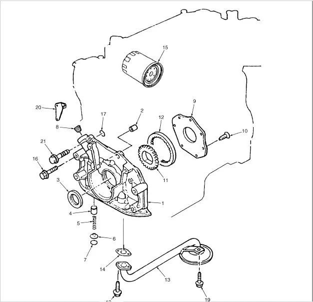
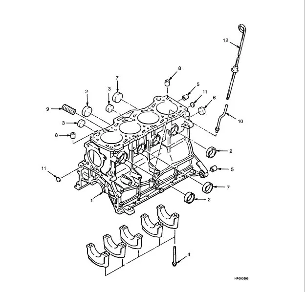
toc..........................................................  1
	1........................................................ 17
		FRAME AND FLOORPLATES (Figure 1-1)................... 20
		OVERHEAD GUARD (Figure 1-2).......................... 23
		ENGINE COVER (Figure 1-3)............................ 24
		SEAT (Figure 1-4).................................... 26
		SEAT (Figure 1-5).................................... 28
		SEAT (Figure 1-6).................................... 30
		LABELS (Figure 1-7).................................. 32
		COUNTERWEIGHT (Figure 1-8)........................... 36
	2........................................................ 39
		CYLINDER HEAD AND COVER (Figure 2-1)................. 42
		CYLINDER BLOCK (Figure 2-2).......................... 44
		OIL PAN AND TIMING GEAR COVER (Figure 2-3)........... 46
		CRANKSHAFT AND PISTON (Figure 2-4)................... 48
		CAMSHAFT AND VALVES (Figure 2-5)..................... 50
		MANIFOLD (Figure 2-6)................................ 52
		ELECTRICAL SYSTEM (Figure 2-7)....................... 54
		FUEL SYSTEM (Figure 2-8)............................. 56
		FUEL SYSTEM (Figure 2-9)............................. 58
		OIL PUMP AND FILTER (Figure 2-10).................... 60
		COOLING SYSTEM (Figure 2-11)......................... 62
		RADIATOR AND HOSES (Figure 2-12)..................... 64
		ENGINE MOUNTS (Figure 2-13).......................... 66
		CYLINDER HEAD (Figure 2-14).......................... 68
		CYLINDER BLOCK (Figure 2-15)......................... 70
		OIL PAN AND TIMING GEAR COVER (Figure 2-16).......... 72
		CRANKSHAFT AND PISTON (Figure 2-17).................. 74
		CAMSHAFT AND VALVES (Figure 2-18).................... 76
		MANIFOLD (Figure 2-19)............................... 78
		ELECTRICAL SYSTEM (Figure 2-20)...................... 80
		OIL PUMP AND FILTER (Figure 2-21).................... 82
		COOLING SYSTEM (Figure 2-22)......................... 84
		RADIATOR AND HOSES (Figure 2-23)..................... 86
		ENGINE MOUNTS (Figure 2-24).......................... 88
		EXHAUST (Figure 2-25)................................ 90
		EXHAUST (Figure 2-26)................................ 92
		EXHAUST (Figure 2-27)................................ 94
		EXHAUST (Figure 2-28)................................ 96
		EXHAUST (Figure 2-29)................................ 98
		EXHAUST (Figure 2-30)................................100
		EXHAUST (Figure 2-31)................................102
	3........................................................105
		THROTTLE ASSEMBLY (Figure 3-1).......................108
		MONOTROL PEDAL (Figure 3-2)..........................110
		THROTTLE LINKAGE (Figure 3-3)........................112
		THROTTLE LINKAGE (Figure 3-4)........................114
		THROTTLE LINKAGE (Figure 3-5)........................115
		CARBURETOR (Figure 3-6)..............................116
		GOVERNOR (Figure 3-7)................................118
		AIR INTAKE AND FILTER (Figure 3-8)...................120
		AIR INTAKE AND FILTER (Figure 3-9)...................122
		AIR INTAKE AND FILTER (Figure 3-10)..................124
		FUEL SYSTEM (Figure 3-11)............................126
		CARBURETOR (Figure 3-12).............................130
		REGULATOR (Figure 3-13)..............................132
		CARBURETOR (Figure 3-14).............................134
		REGULATOR (Figure 3-15)..............................136
		FUEL SYSTEM (Figure 3-16)............................138
		NOZZLE HOLDER (Figure 3-17)..........................140
		FUEL FILTER (Figure 3-18)............................142
		FUEL INJECTION PUMP (Figure 3-19)....................144
		FUEL TANK (Figure 3-20)..............................146
		FUEL TANK (Figure 3-21)..............................148
		FUEL TANK (Figure 3-22)..............................150
	4........................................................153
		ELECTRICAL SYSTEM (Figure 4-1).......................156
		ELECTRICAL SYSTEM (Figure 4-2).......................160
		ELECTRICAL SYSTEM (Figure 4-3).......................164
		ELECTRICAL (Figure 4-4)..............................168
		CONTROL UNIT (Figure 4-5)............................172
		TAIL LIGHTS (Figure 4-6).............................174
		BATTERY (Figure 4-7).................................176
		INSTRUMENT CLUSTER (Figure 4-8)......................178
		LEVER (Figure 4-9)...................................180
		WIRE HARNESS (Figure 4-10)...........................181
		WIRE HARNESS (Figure 4-11)...........................182
		WIRE HARNESS (Figure 4-12)...........................183
		WIRE HARNESS (Figure 4-13)...........................184
		WIRE HARNESS (Figure 4-14)...........................185
		WIRE HARNESS (Figure 4-15)...........................186
		WIRE HARNESS (Figure 4-16)...........................187
		WIRE HARNESS (Figure 4-17)...........................188
		WIRE HARNESS (Figure 4-18)...........................190
		WIRE HARNESS (Figure 4-19)...........................192
		WIRE HARNESS (Figure 4-20)...........................194
		WIRE HARNESS (Figure 4-21)...........................195
		WIRE HARNESS (Figure 4-22)...........................196
		WIRE HARNESS (Figure 4-23)...........................197
		DISTRIBUTOR (Figure 4-24)............................198
		STARTER (Figure 4-25)................................200
		STARTER (Figure 4-26)................................202
		ALTERNATOR (Figure 4-27).............................204
		ALTERNATOR (Figure 4-28).............................206
	5........................................................209
		TORQUE CONVERTOR (Figure 5-1)........................212
		GEAR PUMP (Figure 5-2)...............................214
		SOLENOID VALVE (Figure 5-3)..........................215
		TRANSMISSION HOUSING (Figure 5-4)....................216
		TRANSMISSION GEARS (Figure 5-5)......................218
		TRANSMISSION HYDRAULIC LINES (Figure 5-6)............220
		CLUTCH (Figure 5-7)..................................222
		VALVE (Figure 5-8)...................................224
		DIFFERENTIAL (Figure 5-9)............................226
		DRIVE AXLE (Figure 5-10).............................228
		END PLATE (Figure 5-11)..............................230
	6........................................................233
		STEERING COLUMN (Figure 6-1).........................236
		STEERING PUMP (Figure 6-2)...........................238
		STEERING AXLE (Figure 6-3)...........................240
		STEERING CYLINDER (Figure 6-4).......................242
	7........................................................243
		BRAKE LINKAGE (Figure 7-1)...........................246
		BRAKE LINES (Figure 7-2).............................248
		BRAKE ASSEMBLY (Figure 7-3)..........................250
		PARK BRAKE LEVER (Figure 7-4)........................252
		MASTER CYLINDER (Figure 7-5).........................254
	8........................................................257
		HYDRAULICS (Figure 8-1)..............................260
		HYDRAULIC GEAR PUMP (Figure 8-2).....................264
		HYDRAULIC GEAR PUMP DRIVE (Figure 8-3)...............266
		VALVE ATTACHING PARTS (Figure 8-4)...................268
		VALVE (Figure 8-5)...................................272
		VALVE ATTACHING PARTS (Figure 8-6)...................276
		VALVE (Figure 8-7)...................................278
		TILT CYLINDER (Figure 8-8)...........................282
		TILT CYLINDER (Figure 8-9)...........................284
		TILT CYLINDER (Figure 8-10)..........................286
	9........................................................289
		OUTER MAST (Figure 9-1)..............................292
		INNER MAST (Figure 9-2)..............................294
		FREE LIFT (Figure 9-3)...............................296
		LIFT CYLINDER (Figure 9-4)...........................298
		LIFT CYLINDER (Figure 9-5)...........................300
		CARRIAGE (Figure 9-6)................................302
		LOAD BACKREST EXTENSION (Figure 9-7).................304
		MAST INSTALLATION (Figure 9-8).......................306
		HEADER HOSE (Figure 9-9).............................308
		HEADER HOSE (Figure 9-10)............................310
		FORKS (Figure 9-11)..................................312
		FORKS (Figure 9-12)..................................313
	10.......................................................315
		OUTER MAST (Figure 10-1).............................318
		INNER MAST (Figure 10-2).............................320
		MAIN LIFT (Figure 10-3)..............................322
		FREE LIFT (Figure 10-4)..............................324
		MAIN LIFT CYLINDER (Figure 10-5).....................326
		MAIN LIFT CYLINDER (Figure 10-6).....................328
		FREE-LIFT CYLINDER (Figure 10-7).....................330
		CARRIAGE (Figure 10-8)...............................332
		LOAD BACKREST EXTENSION (Figure 10-9)................334
		MAST INSTALLATION (Figure 10-10).....................336
		HEADER HOSE (Figure 10-11)...........................338
		HEADER HOSE (Figure 10-12)...........................342
		FORKS (Figure 10-13).................................345
		FORKS (Figure 10-14).................................346
	11.......................................................347
		OUTER MAST (Figure 11-1).............................350
		INTERMEDIATE MAST (Figure 11-2)......................352
		INNER MAST (Figure 11-3).............................354
		MAIN LIFT (Figure 11-4)..............................356
		FREE LIFT (Figure 11-5)..............................358
		MAIN LIFT CYLINDER (Figure 11-6).....................360
		MAIN LIFT CYLINDER (Figure 11-7).....................362
		FREE-LIFT CYLINDER (Figure 11-8).....................364
		CARRIAGE (Figure 11-9)...............................366
		LOAD BACKREST EXTENSION (Figure 11-10)...............368
		MAST INSTALLATION (Figure 11-11).....................370
		HEADER HOSE (Figure 11-12)...........................372
		HEADER HOSE (Figure 11-13)...........................374
		FORKS (Figure 11-14).................................377
		FORKS (Figure 11-15).................................378
	12.......................................................379
		SIDE-SHIFT CARRIAGE (Figure 12-1)....................382
		SIDE-SHIFT CYLINDER (Figure 12-2)....................384
		INTEGRAL SIDE-SHIFT CARRIAGE (Figure 12-3)...........386
		INTEGRAL SIDE-SHIFT CARRIAGE (Figure 12-4)...........388
		INTEGRAL SIDE-SHIFT CYLINDER (Figure 12-5)...........390
		INTEGRAL SIDE-SHIFT HYDRAULIC HOSES (Figure 12-6)....391
		INTEGRAL SIDE-SHIFT HYDRAULIC HOSES (Figure 12-7)....392
		AUXILIARY FUNCTION TUBE (Figure 12-8)................394
		AUXILIARY FUNCTION TUBE (Figure 12-9)................396
		WHEEL AND TIRE (Figure 12-10)........................398
		WHEEL AND TIRE (Figure 12-11)........................400
		WHEEL AND TIRE (Figure 12-12)........................402
		WHEEL AND TIRE (Figure 12-13)........................404
		LIFTING EYE (Figure 12-14)...........................405
		LIGHTS (Figure 12-15)................................406
		BACK-UP ALARM (Figure 12-16).........................408
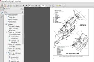
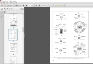
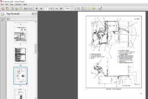
IMAGES PREVIEW OF THE MANUAL:
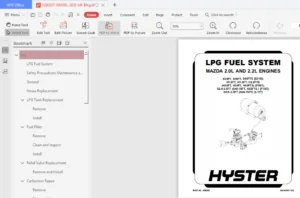
HYSTER H25XM H30XM H35XM H40XM H40XMS (E001) PARTS MANUAL – PDF DOWNLOAD:
PLEASE NOTE:
- This is the SAME exact manual used by your dealers to fix your vehicle.
- The same can be yours in the next 2-3 mins as you will be directed to the download page immediately after paying for the manual.
- Any queries / doubts regarding your purchase, please feel free to contact [email protected]
S.V