Hyster H50CT-BR Parts Manual A297 – Complete Illustrated Catalog PDF 2014
Original price was: $95.00.$19.95Current price is: $19.95.
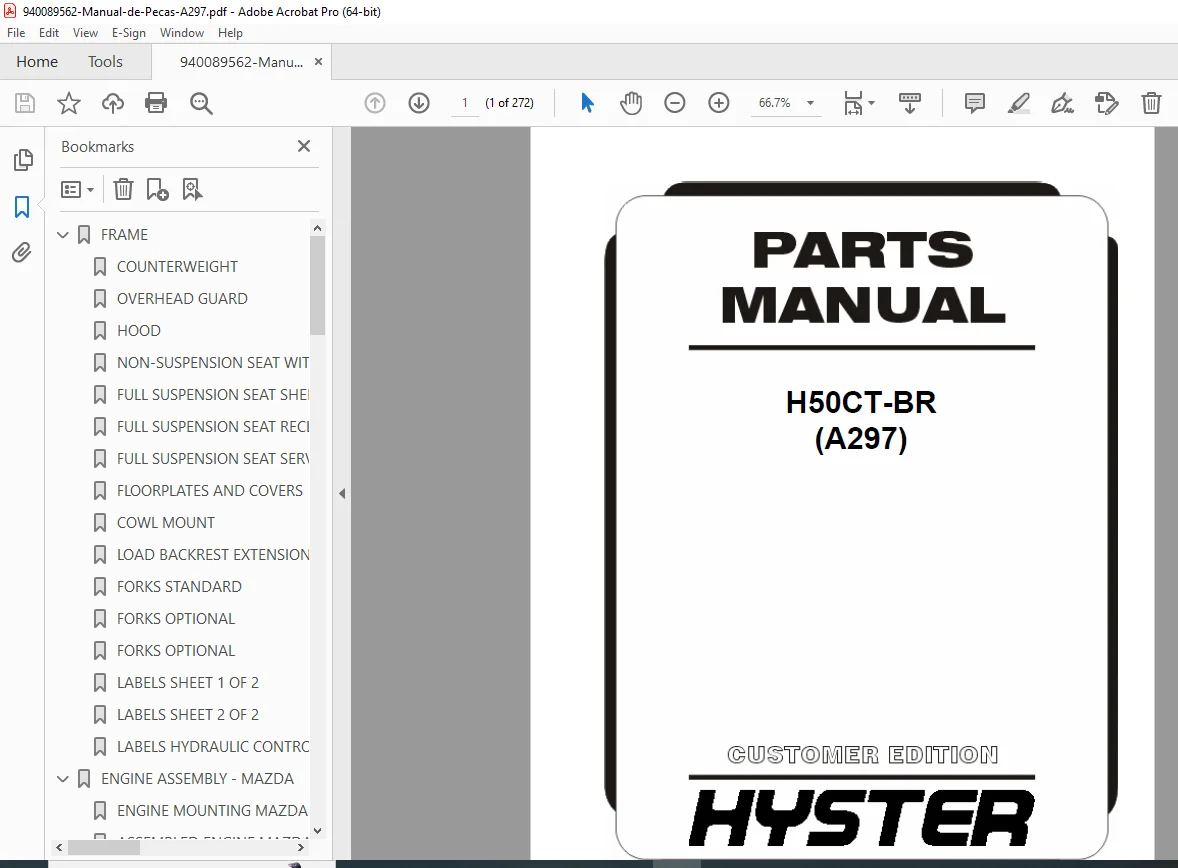
Official Hyster H50CT-BR (A297) illustrated parts manual covering complete forklift components with exploded diagrams and part numbers. This comprehensive 272-page catalog includes all assemblies for Mazda 2.0L and 2.2L LPG engines, transmission, hydraulic systems, mast assemblies, electrical components, and more. Essential reference for parts identification, ordering, and maintenance planning for Hyster forklift technicians and parts departments.
Description
Hyster H50CT-BR Parts Manual A297 – Complete Illustrated Catalog PDF DOWNLOAD 2014
FILE DETAILS
| Specification | Details |
|---|---|
| Manual Name | Hyster H50CT-BR Illustrated Parts Manual |
| Model Covered | H50CT-BR (Unit Code A297) |
| Equipment Type | Counterbalance Forklift – LPG Powered |
| Engine | Mazda 2.0L and 2.2L LPG (Emission Compliant) |
| Edition Date | August 2014 |
| Pages | 272 Pages |
| File Format | |
| File Size | 6.1 MB |
| Quality | Factory Original with High-Quality Exploded Diagrams |
| Document Code | 0860444 |
| Publisher | ©2014 Hyster Company |
| Region | North America |
FULL DESCRIPTION
Official Hyster H50CT-BR Illustrated Parts Catalog
This is the complete factory-authorized Hyster H50CT parts manual PDF for the A297 unit code, published by Hyster Company. This comprehensive A297 forklift parts catalog download provides detailed exploded-view diagrams, complete part numbers, and assembly illustrations for every component on the Hyster H50CT-BR counterbalance forklift equipped with Mazda 2.0L and 2.2L LPG engines.
FORKLIFT SPECIFICATIONS
Model Information:
- Model: Hyster H50CT-BR
- Unit Code: A297
- Fuel Type: LPG (Liquid Propane Gas)
- Engine: Mazda 2.0L and 2.2L (Emission Compliant)
- Transmission: Single Speed with Aluminum Chain Drive
- Mast Configuration: Three-Stage Full Free-Lift
- Region: North America
COMPLETE SECTION BREAKDOWN – 12 MAJOR SECTIONS
SECTION 1 – FRAME
Complete Frame and Body Components:
- Counterweight (Pages 1-2)
- Detailed part numbers for counterweight assembly
- Mounting hardware and fasteners
- Overhead Guard (Page 1-4)
- Complete overhead guard structure
- Post assemblies and cross members
- Mounting brackets and hardware
- Hood Assembly (Page 1-6)
- Engine compartment hood
- Hinges, latches, and supports
- Gas spring assemblies
- Non-Suspension Seat (Page 1-8)
- Without electronic controls
- Seat mounting hardware
- Adjustment mechanisms
- Full Suspension Seat (Pages 1-10 to 1-16)
- Sheet 1 of 3: Complete seat assembly
- Sheet 2 of 3: Recliner and damper kits
- Sheet 3 of 3: Service kits for non-swivel
- Suspension components
- Adjustment controls
- Floorplates and Covers (Page 1-18)
- Floor mat assemblies
- Access panels and covers
- Mounting hardware
- Cowl Mount (Page 1-21)
- Cowl panel assemblies
- Instrument panel mounting
- Load Backrest Extension (Page 1-22)
- Load guard components
- Extension assemblies
- Forks (Pages 1-24 to 1-26)
- Standard forks (Page 1-24)
- Optional forks (Page 1-25)
- Optional configurations (Page 1-26)
- Fork specifications and part numbers
- Labels (Pages 1-28 to 1-32)
- Sheet 1 of 2: General safety labels
- Sheet 2 of 2: Additional warning labels
- Hydraulic control labels
SECTION 2 – ENGINE ASSEMBLY – MAZDA
Complete Mazda 2.0L and 2.2L LPG Engine Components:
- Engine Mounting (Page 2-2)
- Engine mount assemblies
- Vibration isolators
- Mounting brackets and hardware
- Assembled Engine (Page 2-4)
- Complete engine assembly diagram
- Major component identification
- Cylinder Head and Cover (Page 2-6)
- Valve cover assemblies
- Gaskets and seals
- Mounting hardware
- Cylinder Block (Page 2-8)
- Engine block assembly
- Core plugs and fittings
- Timing Gear Cover and Oil Pan (Page 2-10)
- Front cover assembly
- Oil pan and drain plugs
- Gaskets and seals
- Crankshaft and Pistons (Page 2-12)
- Crankshaft assembly
- Piston and connecting rod kits
- Bearings and thrust washers
- Piston rings
- Intake Manifold (Page 2-14)
- Intake manifold assembly
- Gaskets and mounting hardware
- Throttle body mounting
- Exhaust Manifold (Page 2-16)
- Exhaust manifold assembly
- Heat shields
- Gaskets and studs
- Engine Cooling System (Page 2-18)
- Radiator assembly
- Fan and shroud
- Hoses and clamps
- Thermostat housing
- Emission Control System (Page 2-20)
- Emission components
- Sensors and valves
- Vacuum lines
- Oil Pump and Filter (Page 2-22)
- Oil pump assembly
- Oil filter mounting
- Pressure relief valve
- Camshaft and Valves (Page 2-24)
- Camshaft assembly
- Valve train components
- Rocker arms and shafts
- Valve springs and retainers
- Flywheel and Housing Assembly (Page 2-26)
- Flywheel and ring gear
- Flywheel housing
- Mounting bolts
- Exhaust System (Pages 2-28 to 2-30)
- Mazda 2.0L LPG without catalytic converter (Page 2-28)
- Mazda 2.2L LPG without catalytic converter (Page 2-30)
- Muffler assemblies
- Exhaust pipes and clamps
- Cooling System (Page 2-32)
- Complete cooling system layout
- Water pump
- Coolant hoses
- Expansion tank
SECTION 3 – FUEL SYSTEM
Complete LPG Fuel System Components:
- Air Intake System (Page 3-2)
- Air intake ducting
- Pre-cleaner assemblies
- Air Filter Assembly (Page 3-4)
- Air filter housing
- Filter elements
- Restriction indicators
- LPG Fuel Tank and Mounting (Page 3-6)
- Steel strap mounting system
- Tank brackets and hardware
- Safety valves
- Fuel System (Page 3-8)
- Complete fuel delivery system
- Fuel lines and fittings
- Lockoff valves
- Fuel System Hoses and Attaching Parts (Page 3-10)
- High-pressure fuel hoses
- Quick-disconnect fittings
- Mounting clips
- Mixer and Throttle Body Assembly (Page 3-12)
- LPG mixer assembly
- Throttle body components
- Gaskets and seals
- Electronic Pressure Regulator Assembly (Page 3-14)
- Pressure regulator components
- Diaphragms and springs
- Adjustment screws
- Electronic Pressure Regulator Kit (Page 3-16)
- Complete regulator service kit
- Installation hardware
- Throttle Pedal and Attaching Parts (Page 3-18)
- Accelerator pedal assembly
- Cable connections
- Return springs
SECTION 4 – ELECTRICAL SYSTEM
Complete Electrical Components and Wiring:
- Electrical Arrangement (Page 4-2)
- Overall electrical system layout
- Component locations
- Engine Electrical Components (Page 4-4)
- Starter motor
- Alternator
- Sensors and switches
- Engine Control Module (Page 4-6)
- ECM and mounting
- Wiring connectors
- Fuel System Sensors (Page 4-7)
- Pressure sensors
- Temperature sensors
- Oxygen sensors (if equipped)
- Battery and Cables (Page 4-8)
- Battery tray and hold-down
- Battery cables
- Terminal connectors
- Lights (Page 4-10)
- Stop, tail, turn, backup, and strobe lights
- Overhead guard mounting
- Lens assemblies
- Display Cluster (Page 4-12)
- Instrument panel
- Gauges and warning lights
- Hour meter
- Fuse Box – Power Distribution Module (Page 4-14)
- Fuse and relay locations
- Circuit protection
- Power distribution diagram
- Wire Harness (Pages 4-16 to 4-28)
- Powertrain – Mazda 2.0L/2.2L Sheet 1 of 2 (Page 4-16)
- Powertrain – Mazda 2.0L/2.2L Sheet 2 of 2 (Page 4-20)
- RH Chassis – Sheet 1 of 2 (Page 4-24)
- RH Chassis – Sheet 2 of 2 (Page 4-26)
- Lights harness (Page 4-28)
- Complete wiring diagrams with color codes
SECTION 5 – TRANSMISSION
Single Speed Transmission Components:
- Transmission Cooling (Page 5-2)
- Transmission oil cooler
- Cooling lines
- Transmission Mount (Page 5-4)
- Transmission mounting system
- Isolation mounts
- Torque Converter (Page 5-5)
- Complete torque converter assembly
- Seals and bearings
- Torque Converter Housing and Attaching Parts (Page 5-6)
- Housing assembly
- Mounting bolts and hardware
- Transmission Housing and Assembly (Page 5-8)
- Single speed, aluminum chain drive
- Case assemblies
- Gaskets and seals
- Stator Support Housing (Page 5-12)
- Support housing components
- Thrust bearings
- Input/Forward Clutch (Page 5-14)
- Forward clutch assembly
- Clutch plates and springs
- Seals and snap rings
- Counter/Reverse Clutch (Page 5-16)
- Reverse clutch assembly
- Friction discs
- Pressure plates
SECTION 6 – DRIVE AXLE
Complete Drive Axle Assembly:
- Drive Axle Assembly (Page 6-2)
- Complete axle assembly
- Differential components
- Axle shafts and bearings
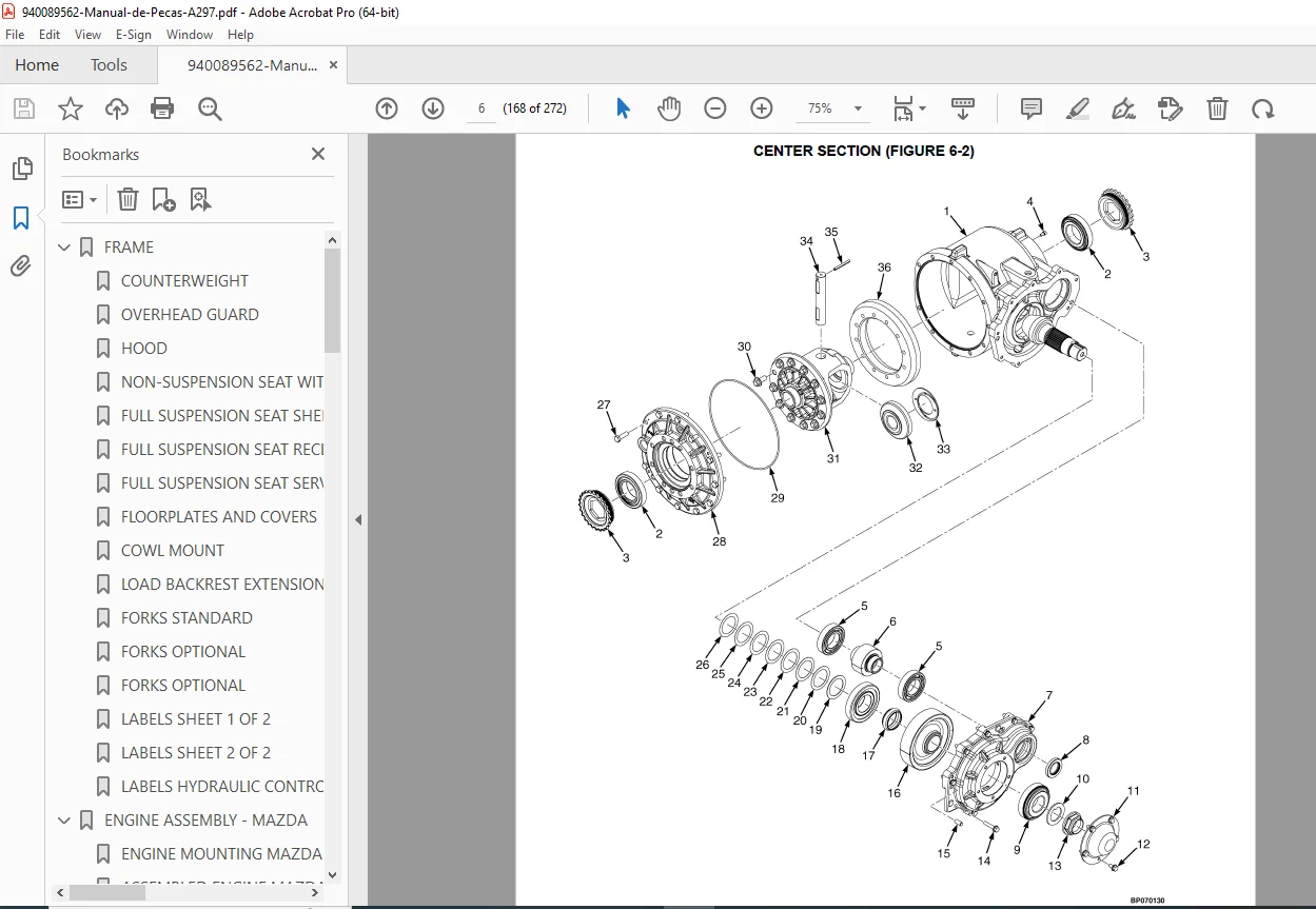
- Center Section (Page 6-6)
- Differential carrier
- Ring and pinion gears
- Bearing caps
- Drive Tire and Wheel (Pages 6-8 to 6-9)
- Standard pneumatic tires (Page 6-8)
- Standard solid tires (Page 6-9)
- Wheel assemblies
- Rim and tire specifications
SECTION 7 – STEERING SYSTEM
Complete Steering Components:
- Steering Wheel and Column (Page 7-2)
- Non-isolated LPG configuration
- Steering wheel assembly
- Column covers
- Steering Column Assembly (Page 7-4)
- Non-isolated LPG
- Column mounting
- Universal joints
- Steering Axle and Attaching Parts (Page 7-6)
- Steer axle assembly
- King pins and bearings
- Axle pivots
- Steering Cylinder (Page 7-8)
- Hydraulic steering cylinder
- Rod and gland assemblies
- Seals and O-rings
- Steer Tire and Wheel (Pages 7-9 to 7-10)
- Standard pneumatic tires (Page 7-9)
- Standard solid tires (Page 7-10)
- Wheel assemblies and hardware
SECTION 8 – BRAKE SYSTEM
Complete Brake System Components:
- Brake Assembly (Page 8-2)
- Brake drum and shoes
- Wheel cylinders
- Hardware kits
- Brake Pedal Linkage (Page 8-4)
- Brake pedal assembly
- Linkage rods
- Return springs
- Park Brake (Page 8-6)
- Parking brake mechanism
- Cables and adjusters
- Release handles
SECTION 9 – HYDRAULIC SYSTEM
Complete Hydraulic System:
- Hydraulic Supply and Return (Page 9-2)
- Main hydraulic lines
- Return filters
- Fittings and adapters
- Hydraulic Hoses – Steering (Page 9-4)
- Power steering hoses
- Pressure and return lines
- Hydraulic Hoses – Tilt, Hoist and Auxiliary (Page 9-6)
- Function control hoses
- High-pressure rated hoses
- Hydraulic Filter (Page 9-8)
- Filter assembly
- Filter elements
- Bypass valves
- Gear Pump Assembly (Page 9-10)
- Hydraulic gear pump
- Drive couplings
- Pump mounting
- Hand Levers (Page 9-12)
- Control lever assemblies
- Grips and knobs
- Hydraulic Control Valve – Manual 3 Function (Page 9-14)
- Complete control valve assembly
- Spool valves
- Springs and seals
- Control Valve Lockout Group (Page 9-16)
- Lockout mechanism
- Safety interlocks
- Valve Assembly, Lift and Tilt (Page 9-18)
- Manual control valve – three function
- Lift and tilt spools
- Valve Assembly, Auxiliary (Page 9-20)
- Manual control valve – three function
- Auxiliary function spool
- Valve Assembly, Outlet Section (Page 9-22)
- Manual control valve – three function
- Outlet section components
- Steering Control Unit (Page 9-24)
- Priority steering valve
- Load sensing components
- Tilt Cylinder and Mast Installation (Page 9-26)
- Tilt cylinder mounting
- Mast attachment points
- Tilt Cylinder Assembly (Page 9-28)
- Complete tilt cylinder
- Rod and gland assemblies
- Seal kits
SECTION 10 – MAST – THREE STAGE FULL FREE-LIFT
Complete Mast Assembly Components:
- Outer Mast (Page 10-2)
- Outer mast channels
- Roller assemblies
- Top cap and base
- Intermediate Mast and Main Lift (Page 10-4)
- Intermediate mast rails
- Main lift chain system
- Sheaves and anchors
- Inner Mast and Free-Lift (Page 10-8)
- Inner mast channels
- Free-lift chain system
- Carriage rollers
- Main Lift Cylinder Assembly (Page 10-12)
- Three-stage full free lift cylinder
- Cylinder stages
- Seals and bearings
- Free Lift Cylinder Assembly (Page 10-16)
- Free lift cylinder components
- Mounting hardware
- Side Shift Carriage – Integral Class II (Page 10-18)
- Side-shifting carriage
- Fork positioning bars
- Hook assemblies
- Header Hose and Attaching Parts (Page 10-20)
- Three-function hoses
- Mast hose routing
- Quick couplers
SECTION 11 – OPTIONS
Optional Equipment and Accessories:
- Mirrors (Page 11-2)
- Rearview mirror assemblies
- Mounting brackets
- Audible Backup Alarm (Page 11-3)
- Backup alarm device
- Wiring harness
- Fire Extinguisher (Page 11-4)
- Fire extinguisher bracket
- Mounting hardware
- Integral Side-Shift Hydraulic Hoses (Page 11-5)
- Three-stage full free-lift configuration
- Side-shift function hoses
- Integral Side-Shift Cylinder (Page 11-6)
- Side-shift hydraulic cylinder
- Mounting pins
- Seal kits
SECTION 12 – NUMERICAL INDEX
- Complete Part Number Index
- Alphabetical and numerical part number listing
- Cross-reference to page locations
- Quick part lookup system
KEY FEATURES OF THIS PARTS MANUAL
✓ 272 Pages of Detailed Diagrams – Comprehensive exploded-view illustrations
✓ Complete Part Numbers – Every component clearly identified
✓ Factory Original Documentation – Official Hyster publication
✓ 12 Major Sections – Organized by system for easy navigation
✓ Quick Reference Tabs – Thumb-indexed sections for fast access
✓ Numerical Index – Complete part number cross-reference
✓ All Assembly Groups – Frame to electrical to hydraulics
✓ Engine Components – Complete Mazda 2.0L and 2.2L LPG parts
✓ Mast Assemblies – Three-stage full free-lift detailed breakdown
✓ Wire Harness Diagrams – Complete electrical routing
✓ Option Packages – All available accessories and attachments
IDEAL FOR:
- Hyster Dealership Parts Departments
- Independent Forklift Repair Shops
- Fleet Maintenance Managers
- Parts Inventory Specialists
- Forklift Service Technicians
- Equipment Rental Companies
- Warehouse Maintenance Teams
- Material Handling Equipment Suppliers
- Forklift Rebuilders
- Parts Wholesalers and Distributors
WHY THIS MANUAL IS ESSENTIAL:
This Hyster LPG forklift illustrated parts list is the definitive reference for identifying, ordering, and managing replacement parts for the H50CT-BR (A297) model. The detailed exploded-view diagrams show exactly how components fit together, making it easy to identify the correct part numbers for ordering. With complete coverage of the Mazda LPG engine, transmission, hydraulic systems, and mast assemblies, this manual eliminates guesswork and ensures you order the right parts the first time.
The numerical index provides quick access to any part number, while the organized section structure lets you navigate directly to the system you’re working on. Wire harness diagrams show exact routing and connector locations, crucial for electrical troubleshooting and repair.
📋 INSTANT DOWNLOAD – ACCURATE PARTS ORDERING STARTS NOW! This official Hyster H50CT parts manual PDF is used by Hyster dealerships and parts departments worldwide to ensure accurate part identification and ordering. With 272 pages of factory exploded-view diagrams and complete part numbers, you’ll eliminate ordering errors, reduce downtime, and maintain your Hyster forklift with genuine parts confidence. Stop struggling with incomplete parts information or ordering wrong components – download this official catalog now and have instant access to every part number and assembly diagram for your H50CT-BR (A297) forklift!