Hyster J160 Service Manual – PDF DOWNLOAD
Original price was: $98.95.$29.95Current price is: $29.95.
Hyster J160 Service Manual – PDF DOWNLOAD
PART NO. 1534737
Description
Hyster J160 Service Manual – PDF DOWNLOAD
DESCRIPTION:
Hyster J160 Service Manual – PDF DOWNLOAD
PART NO. 1534737
SAFETY PRECAUTIONS MAINTENANCE AND REPAIR
• When lifting parts or assemblies,make sure all slings, chains, or cables are correctly fastened, and
that the load being lifted is balanced. Make sure the crane, cables, and chains have the capacity
to support the weight of the load.
• Do not lift heavy parts by hand, use a lifting mechanism.
• Wear safety glasses.
• DISCONNECT THE BATTERY CONNECTOR before doing any maintenance or repair on electric
lift trucks. Disconnect the battery ground cable on internal combustion lift trucks.
• Always use correct blocks to prevent the unit fromrolling or falling. See HOWTO PUT THE LIFT
TRUCK ON BLOCKS in the Operating Manual or the Periodic Maintenance section.
• Keep the unit clean and the working area clean and orderly.
• Use the correct tools for the job.
• Keep the tools clean and in good condition.
• Always use HYSTER APPROVED parts when making repairs. Replacement parts must meet
or exceed the specifications of the original equipment manufacturer.
• Make sure all nuts, bolts, snap rings, and other fastening devices are removed before using force
to remove parts.
• Always fasten a DO NOT OPERATE tag to the controls of the unit when making repairs, or if the
unit needs repairs.
• Be sure to follow the WARNING and CAUTION notes in the instructions.
• Gasoline, Liquid Petroleum Gas (LPG), Compressed Natural Gas (CNG), and Diesel fuel are
flammable. Be sure to follow the necessary safety precautions when handling these fuels and
when working on these fuel systems.
• Batteries generate flammable gas when they are being charged. Keep fire and sparks away from
the area. Make sure the area is well ventilated.
TABLE OF CONTENTS:
Hyster J160 Service Manual – PDF DOWNLOAD
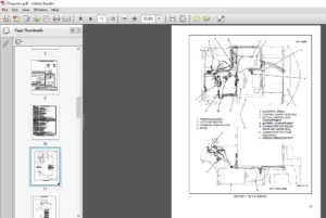
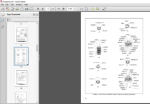
1534737-2200SRM1058-(09-2008)-US-EN.............................................  1
	toc.........................................................................  1
		Troubleshooting and Adjustments Using the AC Controls Program (E........  1
		Safety Precautions Maintenance and Repair...............................  2
		General.................................................................  5
			Computer Requirements...............................................  5
			Software, Install...................................................  5
			Language Selection..................................................  5
			Demo Mode...........................................................  6
			Connect PC to Lift Truck............................................ 10
			Starting AC Controls Program........................................ 12
		Lift Truck Control Setup................................................ 16
			Change Lift Truck Serial Number or Hourmeter........................ 16
			Setting Factory Default Values or Changing Lift Truck Parameters.... 18
			Create New Custom Lift Truck Configuration.......................... 24
			Lift Truck Configuration Properties................................. 27
			Import New Lift Truck Configuration From Disk....................... 30
			Delete Custom Lift Truck Configuration or Password File............. 32
		Dash Display............................................................ 35
			Custom Display Languages............................................ 35
			Download Display Language........................................... 37
			Clear Operator Log.................................................. 37
		Password Functions...................................................... 40
			Enable/Disable Password and Lift Truck Inspection Functions......... 40
				Truck Inspection Checklist...................................... 40
				Password........................................................ 40
			Password Properties................................................. 40
			Create New Password File............................................ 45
			Download Passwords.................................................. 47
			Upload Passwords.................................................... 47
		Reports Menu............................................................ 51
			Devices Report...................................................... 51
			Custom Report....................................................... 51
			Password Report..................................................... 51
			Operator Report..................................................... 58
			Current Settings Report............................................. 61
			Status Code Report.................................................. 64
			Status Codes Log.................................................... 67
		Troubleshooting......................................................... 69
			Diagnostics......................................................... 69
		Help Menu............................................................... 72
			General............................................................. 72
			Contents............................................................ 72
			Technical Support................................................... 72
			About Electric Truck AC Controls Program............................ 72
1554633-2200SRM1087-(08-2005)-US-EN............................................. 79
	toc......................................................................... 79
		AC Motor Controllers/ Display Panel..................................... 79
		Safety Precautions Maintenance and Repair............................... 80
		Description............................................................. 83
			General............................................................. 83
			Description......................................................... 83
				AC Motors....................................................... 83
				ZAPI™ AC Motor Controller....................................... 83
				Principles of Operation......................................... 84
				Controller Thermal Management................................... 85
				Controller Area Network (CANbus)................................ 85
			Discharging the Capacitors.......................................... 85
		AC Motor Controller Repair.............................................. 86
			General............................................................. 86
				Special Precautions............................................. 86
			Thermal Sensors..................................................... 87
			Motor Controller, Replace........................................... 87
		Controller Checks and Adjustments....................................... 87
		Function Parameters..................................................... 88
			General............................................................. 88
		Function Parameter Descriptions......................................... 89
			Parameters.......................................................... 89
				Top Speed Forward............................................... 89
				Top Speed Reverse............................................... 89
				Acceleration.................................................... 89
				Regen Braking................................................... 89
				Auto Deceleration............................................... 89
				Extended Shift.................................................. 89
				Pump Acceleration............................................... 90
				Tilt/Auxiliary Pump Acceleration................................ 90
				Low Lift Speed.................................................. 90
				Maximum Lift Speed.............................................. 90
				Maximum Lowering Speed.......................................... 90
				Tilt Speed...................................................... 90
				3rd Function.................................................... 90
				3rd Function Speed.............................................. 90
				4th Function.................................................... 90
				4th Function Speed.............................................. 91
				Battery Voltage................................................. 91
				Lift Interrupt.................................................. 91
				BDI Adjustment (Early Models)................................... 91
				BDI Adjustment (Later Models)................................... 91
				BDI Decrement Time.............................................. 91
				Service Reminder................................................ 92
				Custom.......................................................... 92
				Restore Defaults................................................ 92
		Calibration Parameters.................................................. 92
			Throttle Calibration................................................ 92
			Steering Calibration................................................ 92
		Display Panel........................................................... 92
			General............................................................. 92
				Premium Display Panel........................................... 92
				Standard Display Panel.......................................... 92
		Display Functions and Features.......................................... 93
			Key-On Initialization............................................... 93
			Standard Display.................................................... 93
			Premium Display..................................................... 95
			Lift Truck Inspection Function...................................... 95
			Access to Service Functions......................................... 96
			Service Functions................................................... 96
			Performance Modes................................................... 97
			Battery Discharge Indication (BDI).................................. 98
			Hourmeter........................................................... 98
			Status Code List.................................................... 98
		Dash Display Service Menu Navigation.................................... 99
			General............................................................. 99
			Moving Through Menu Selections...................................... 99
			Editing and Adding Information...................................... 99
		ETACC Test..............................................................100
			Manual Hydraulics:..................................................100
			Electro-Hydraulics:.................................................100
		Troubleshooting.........................................................100
			General.............................................................100
			Status Codes........................................................101
			Controller Connector Pin Outs.......................................192
			Valve Driver Module (Electro-Hydraulic Valve Option)................193
			Hydraulic Lever Console (Electro-Hydraulic Option Only).............194
			Dash Display........................................................194
			System Logic Diagrams...............................................195
	tables...................................................................... 79
		Table 1. Traction Parameters............................................ 88
		Table 2. Transistor Lift With Manual Valve Parameters................... 88
		Table 3. Transistor Lift With Electro-Hydraulic Valve Parameters........ 88
		Table 4. List of Status Codes...........................................101
		Table 5. Connector A....................................................192
		Table 6. Connector C....................................................192
		Table 7. Connector D - Standard Model...................................193
		Table 8. Connector D - Premium Model....................................193
		Table 9. Connector B....................................................193
		Table 10. Connector C...................................................193
1554633-2200SRM1087-(10-2006)-US-EN.............................................201
	toc.........................................................................201
		AC Motor Controllers/Display Panel......................................201
		Safety Precautions Maintenance and Repair...............................202
		Description.............................................................205
			General.............................................................205
			Description.........................................................205
				AC Motors.......................................................205
				ZAPI™ AC Motor Controller.......................................205
				Principles of Operation.........................................206
				Controller Thermal Management...................................207
				Controller Area Network (CANbus)................................207
			Discharging the Capacitors..........................................207
		AC Motor Controller Repair..............................................208
			General.............................................................208
				Special Precautions.............................................208
			Thermal Sensors.....................................................209
			Motor Controller, Replace...........................................209
		Controller Checks and Adjustments.......................................209
		Function Parameters.....................................................210
			General.............................................................210
		Function Parameter Descriptions.........................................211
			Parameters..........................................................211
				Top Speed Forward...............................................211
				Top Speed Reverse...............................................211
				Acceleration....................................................211
				Regen Braking...................................................212
				Auto Deceleration...............................................212
				Extended Shift..................................................212
				Pump Acceleration...............................................212
				Tilt/Auxiliary Pump Acceleration................................212
				Low Lift Speed..................................................212
				Maximum Lift Speed..............................................212
				Maximum Lowering Speed..........................................212
				Tilt Speed......................................................213
				3rd Function....................................................213
				3rd Function Speed..............................................213
				4th Function....................................................213
				4th Function Speed..............................................213
				Battery Voltage.................................................213
				Lift Interrupt..................................................213
				BDI Adjustment (Early Models)...................................213
				BDI Adjustment (Later Models)...................................214
				BDI Decrement Time..............................................214
				Service Reminder................................................214
				Custom..........................................................215
				Restore Defaults................................................215
		Calibration Parameters..................................................215
			Throttle Calibration................................................215
			Steering Calibration................................................215
		Display Panel...........................................................216
			General.............................................................216
				Premium Display Panel...........................................216
				Standard Display Panel..........................................216
		Display Functions and Features..........................................217
			Key-On Initialization...............................................217
			Standard Display....................................................218
			Premium Display.....................................................218
			Lift Truck Inspection Function......................................218
			Access to Service Functions.........................................219
			Service Functions...................................................219
			Performance Modes...................................................221
			Battery Discharge Indication (BDI)..................................221
			Hourmeter...........................................................222
			Status Code List....................................................222
		Dash Display Service Menu Navigation....................................222
			General.............................................................222
			Moving Through Menu Selections......................................222
			Editing and Adding Information......................................223
		ETACC Test..............................................................223
			Manual Hydraulics...................................................223
			Electro-Hydraulics..................................................223
		Troubleshooting.........................................................224
			General.............................................................224
			Status Codes........................................................224
			Controller Connector Pin Outs.......................................316
			Valve Driver Module (Electro-Hydraulic Valve Option)................317
			Hydraulic Lever Console (Electro-Hydraulic Option Only).............318
			Dash Display........................................................318
			System Logic Diagrams...............................................319
	tables......................................................................201
		Table 1. Traction Parameters............................................210
		Table 2. Transistor Lift With Manual Valve Parameters...................210
		Table 3. Transistor Lift With Electro-Hydraulic Valve Parameters........211
		Table 4. List of Status Codes...........................................225
		Table 5. Connector A....................................................316
		Table 6. Connector C....................................................316
		Table 7. Connector D - Standard Model...................................317
		Table 8. Connector D - Premium Model....................................317
		Table 9. Connector B....................................................317
		Table 10. Connector C...................................................317
1554634-2200SRM1078-(07-2005)-US-EN.............................................325
	toc.........................................................................325
		Electrical System.......................................................325
		Safety Precautions Maintenance and Repair...............................326
		Introduction............................................................329
			General.............................................................329
			Discharging the Capacitors..........................................329
			Emissions...........................................................331
				Electromagnetic Interference....................................331
		Motor Controllers.......................................................331
			Controllers.........................................................331
				Remove..........................................................331
				Install.........................................................332
			Hydraulics Contactor................................................333
				Remove..........................................................333
				Disassemble.....................................................333
				Assemble........................................................333
				Install.........................................................333
		Contactor Panel.........................................................334
			Main Contactor......................................................334
				Remove..........................................................334
				Disassemble.....................................................335
				Assemble........................................................335
				Install.........................................................335
				Contactor Coil..................................................336
				Contactor Tips..................................................336
			Fuses...............................................................336
		Display Units...........................................................337
			Features............................................................337
			Replace.............................................................338
		Key Switch..............................................................339
			Replace.............................................................339
		Directional Controls....................................................340
			Directional Control Switches........................................340
			Accelerator Switches and Pedal Assembly.............................341
			Install.............................................................341
			Calibrate...........................................................344
			MONOTROL™ Directional Control.......................................344
		Brakes..................................................................346
			Brake Switch........................................................346
				Adjust or Replace...............................................346
			Master Cylinder Indicator...........................................346
			Parking Brake Disengage.............................................347
				Override Mode...................................................347
		Horn Components and Steering Encoder....................................348
			Horn Components.....................................................348
				Horn............................................................348
				Horn Button and Contacts........................................349
			Steering Encoder....................................................349
		Hood and Seat Switches..................................................350
			Hood Position Switches..............................................350
			Seat Switch.........................................................350
		Steer Angle Potentiometer...............................................350
			General.............................................................350
			Operation...........................................................350
				Example.........................................................351
			Position Steer Tire for Straight Travel.............................351
			Install.............................................................352
				Set Potentiometer to Midpoint...................................352
				Install to Steer Axle...........................................352
				Calibrate.......................................................353
			Test................................................................353
		Wiring Harness..........................................................354
	tables......................................................................325
		Table 1. Potentiometer Specifications...................................353
1554637-8000SRM1081-(04-2007)-US-EN.............................................361
	toc.........................................................................361
		Diagrams................................................................361
		Safety Precautions Maintenance and Repair...............................362
1554637-8000SRM1081-(11-2004)-US-EN.............................................395
	toc.........................................................................395
		Diagrams................................................................395
		Safety Precautions Maintenance and Repair...............................396
HYSTER J160 SERVICE MANUAL – PDF DOWNLOAD:
IMAGES PREVIEW OF THE MANUAL:
PLEASE NOTE:
- This is the SAME MANUAL used by the dealerships to diagnose your vehicle
- No waiting for couriers / posts as this is a PDF manual and you can download it within 2 minutes time once you make the payment.
- Your payment is all safe and the delivery of the manual is INSTANT – You will be taken to the DOWNLOAD PAGE.
- So have no hesitations whatsoever and write to us about any queries you may have : heydownloadss @gmail.com
S.V