Hyster K005 (H70-120XM) Service Manual – PDF DOWNLOAD
Original price was: $89.95.$29.95Current price is: $29.95.
Hyster K005 (H70-120XM) Service Manual – PDF DOWNLOAD
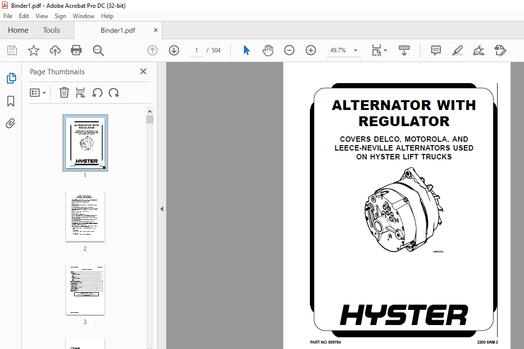
PART NO. 899784
Description
Hyster K005 (H70-120XM) Service Manual – PDF DOWNLOAD
DESCRIPTION:
Hyster K005 (H70-120XM) Service Manual – PDF DOWNLOAD
PART NO. 899784
SAFETY PRECAUTIONS MAINTENANCE AND REPAIR :
• When lifting parts or assemblies, make sure all slings, chains, or cables are correctly
fastened, and that the load being lifted is balanced. Make sure the crane, cables, and
chains have the capacity to support the weight of the load.
• Do not lift heavy parts by hand, use a lifting mechanism.
• Wear safety glasses.
• DISCONNECT THE BATTERY CONNECTOR before doing any maintenance or repair
on electric lift trucks.
• Disconnect the battery ground cable on internal combustion lift trucks.
• Always use correct blocks to prevent the unit from rolling or falling. See HOW TO PUT
THE LIFT TRUCK ON BLOCKS in the Operating Manual or the Periodic Maintenance
section.
• Keep the unit clean and the working area clean and orderly.
• Use the correct tools for the job.
• Keep the tools clean and in good condition.
• Always use HYSTER APPROVED parts when making repairs. Replacement parts
must meet or exceed the specifications of the original equipment manufacturer.
• Make sure all nuts, bolts, snap rings, and other fastening devices are removed before
using force to remove parts.
• Always fasten a DO NOT OPERATE tag to the controls of the unit whenmaking repairs,
or if the unit needs repairs.
• Be sure to follow the WARNING and CAUTION notes in the instructions.
• Gasoline, Liquid Petroleum Gas (LPG), Compressed Natural Gas (CNG), and Diesel fuel
are flammable. Be sure to follow the necessary safety precautions when handling these
fuels and when working on these fuel systems.
• Batteries generate flammable gas when they are being charged. Keep fire and sparks
away from the area. Make sure the area is well ventilated.
TABLE OF CONTENTS:
Hyster K005 (H70-120XM) Service Manual – PDF DOWNLOAD
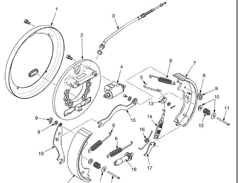
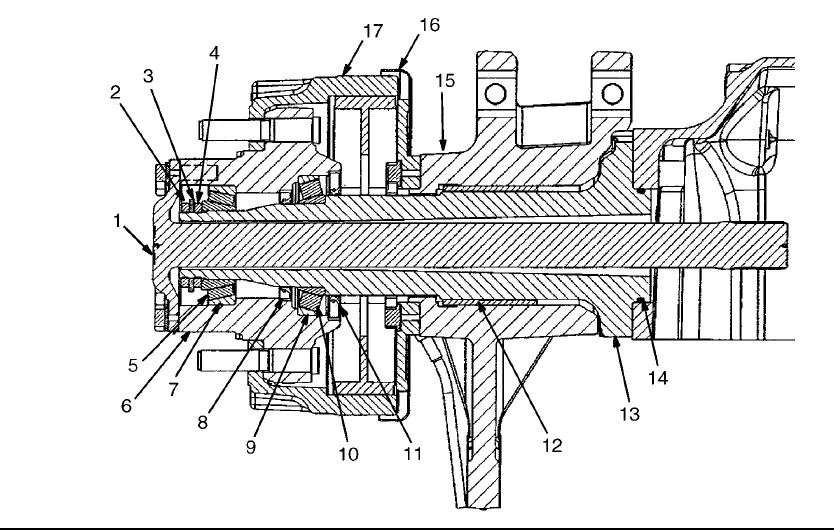
Hyster-H80XM-Alternator-With-Regulator-899784-2200SRM0002-(12-2004)-US-EN................  1
	toc..................................................................................  1
		Alternator with Regulator........................................................  1
		Safety Precautions Maintenance and Repair........................................  2
		General..........................................................................  5
		Description......................................................................  5
		Alternator Repair................................................................  7
			Alternator Type A............................................................  7
				Remove and Disassemble...................................................  7
				Clean....................................................................  8
				Assemble.................................................................  9
				Install..................................................................  9
			Alternator Type B............................................................ 12
				Remove and Disassemble................................................... 12
				Clean.................................................................... 12
				Assemble................................................................. 13
				Install.................................................................. 14
		General Check and Adjustment..................................................... 15
		Low Output Check (Type A or Type B).............................................. 15
		High Output Check (Type A or Type B)............................................. 17
		Brushes Circuit Check............................................................ 18
			Delco Alternators............................................................ 18
			Motorola Alternators......................................................... 19
		Diodes Check..................................................................... 20
		Diode Bridge Check............................................................... 20
			Delco and Leece-Neville Alternators.......................................... 20
			Motorola Alternators......................................................... 20
		Rotor Field Winding Check........................................................ 21
		Stator Windings Check............................................................ 22
		Voltage Regulator Check.......................................................... 22
		Troubleshooting.................................................................. 22
Hyster-H80XM-Brake-System-1466229-1800SRM0734-(05-2005)-US-EN............................ 27
	toc.................................................................................. 27
		Brake System..................................................................... 27
		Safety Precautions Maintenance and Repair........................................ 28
		General.......................................................................... 31
		Description and Operation........................................................ 31
			Brake Booster and Master Cylinder............................................ 31
			Service Brake Assembly....................................................... 31
			Parking Brake................................................................ 32
		Brake Shoe Assemblies Repair..................................................... 32
			Remove and Disassemble....................................................... 32
			Clean........................................................................ 33
			Inspect...................................................................... 35
			Assemble and Install......................................................... 35
		Brake Booster and Master Cylinder Repair......................................... 38
			Remove....................................................................... 38
			Disassemble.................................................................. 38
			Clean and Inspect............................................................ 38
			Assemble..................................................................... 38
			Install...................................................................... 40
			Brake Booster Filter, Replace................................................ 41
		Parking Brake Repair............................................................. 41
			Remove and Disassemble....................................................... 41
			Assemble and Install......................................................... 41
		Brake System Air Removal......................................................... 41
		Brake Pedal Adjustment........................................................... 42
		Parking Brake Adjustment......................................................... 42
		Parking Brake Not Applied Switch Test............................................ 43
		Parking Brake Switch Test ( MONOTROL® Pedal Only)................................ 43
		Brake Shoes Adjustment........................................................... 44
		Troubleshooting.................................................................. 44
Hyster-H80XM-Capacities-and-Specifications-1467764-8000SRM0738-(05-2004)-US-EN........... 49
	toc.................................................................................. 49
		Capacities and Specifications.................................................... 49
		Safety Precautions Maintenance and Repair........................................ 50
		Lift Truck Weights............................................................... 53
		Electrical System................................................................ 53
		Stall Speeds..................................................................... 53
		Capacities....................................................................... 54
		Tire Pressure.................................................................... 54
		Engine Specifications............................................................ 55
		Transmission Oil Pressures....................................................... 56
		Hydraulic System................................................................. 57
		Mast Speeds...................................................................... 58
		Torque Specifications............................................................ 58
			Brake System................................................................. 58
			Differential................................................................. 58
			Drive Axle................................................................... 59
			Engine, GM V-6 4.3 Liter..................................................... 59
			Engine, Perkins 1004-42...................................................... 60
			Frame........................................................................ 60
			Lift Cylinders............................................................... 60
			Main Control Valve........................................................... 60
			Masts........................................................................ 60
			Powershift Transmission...................................................... 61
			Steering System.............................................................. 61
			Tilt Cylinders............................................................... 61
			Hydrostatic Components....................................................... 61
	tables............................................................................... 49
		Table 1. Single-Speed............................................................ 56
		Table 2. Two-Speed............................................................... 56
		Table 3. Hydrostatic Transmission................................................ 57
Hyster-H80XM-Drive-Axle-1466247-1400SRM0731-(09-2003)-US-EN.............................. 65
	toc.................................................................................. 65
		Drive Axle....................................................................... 65
		Safety Precautions Maintenance and Repair........................................ 66
		General.......................................................................... 69
		Description...................................................................... 69
		Drive Axle Repair................................................................ 69
			Remove and Disassemble....................................................... 69
			Clean and Inspect............................................................ 71
			Assemble and Install......................................................... 71
		Troubleshooting.................................................................. 73
Hyster-H80XM-Dual-Fuel-System-1467755-0900SRM0768-(05-2001)-US-EN........................ 77
	toc.................................................................................. 77
		Dual Fuel System................................................................. 77
		Safety Precautions Maintenance and Repair........................................ 78
		General.......................................................................... 81
		Description...................................................................... 82
		Operation........................................................................ 82
		LPG Solenoid Valve Repair........................................................ 82
		Fuel Selector Switch Repair...................................................... 82
		Adjustments...................................................................... 83
		Troubleshooting.................................................................. 83
Hyster-H80XM-Electronic-Engine-Control-1467758-2200SRM0766-(08-2002)-US-EN............... 87
	toc.................................................................................. 87
		Electronic Engine Control........................................................ 87
		Safety Precautions Maintenance and Repair........................................ 88
		General.......................................................................... 91
		Description and Operation........................................................ 91
			General...................................................................... 91
			ECM (Electronic Control Module).............................................. 91
				Diagnostic Connector..................................................... 91
				How ECM Begins Operation................................................. 93
			Electronic Engine Control.................................................... 93
				What ECM Does............................................................ 93
				Pulse Generator, EST Distributor......................................... 95
				EST Module............................................................... 95
				When Engine is Being Started............................................. 96
				When Engine is Running................................................... 97
				Electronic Control Module (ECM) With EST Distributor, Correction......... 97
			Fuel Control................................................................. 98
			Injection Throttle Body...................................................... 99
				Fuel Injectors........................................................... 99
				Fuel Pressure Regulator.................................................. 99
			Governor Throttle Body Assembly..............................................100
				Throttle Position Sensor (TPS)...........................................101
				Idle Air Control.........................................................101
				Vacuum Ports.............................................................102
				Fuel Pump................................................................102
			ECM Sensors and Controllers..................................................103
				Manifold Absolute Pressure (MAP).........................................103
				Coolant Temperature Sensor (CTS).........................................103
Hyster-H80XM-Electronic-Engine-Control-1474823-2200SRM0781-(01-2000)-US-EN...............107
	.....................................................................................107
	.....................................................................................108
	.....................................................................................109
	.....................................................................................110
	.....................................................................................111
	.....................................................................................112
	.....................................................................................113
	.....................................................................................114
	.....................................................................................115
	.....................................................................................116
	.....................................................................................117
	.....................................................................................118
	.....................................................................................119
	.....................................................................................120
	.....................................................................................121
	.....................................................................................122
	.....................................................................................123
	.....................................................................................124
	.....................................................................................125
	.....................................................................................126
	.....................................................................................127
	.....................................................................................128
Hyster-H80XM-Electronic-Engine-Control-1474824-2200SRM0782-(03-2000)-US-EN...............129
	.....................................................................................129
	.....................................................................................130
	.....................................................................................131
	.....................................................................................132
	.....................................................................................133
	.....................................................................................134
	.....................................................................................135
	.....................................................................................136
	.....................................................................................137
	.....................................................................................138
	.....................................................................................139
	.....................................................................................140
	.....................................................................................141
	.....................................................................................142
	.....................................................................................143
	.....................................................................................144
	.....................................................................................145
	.....................................................................................146
	.....................................................................................147
	.....................................................................................148
	.....................................................................................149
	.....................................................................................150
	.....................................................................................151
	.....................................................................................152
	.....................................................................................153
	.....................................................................................154
	.....................................................................................155
	.....................................................................................156
	.....................................................................................157
	.....................................................................................158
	.....................................................................................159
	.....................................................................................160
	.....................................................................................161
	.....................................................................................162
	.....................................................................................163
	.....................................................................................164
	.....................................................................................165
	.....................................................................................166
	.....................................................................................167
	.....................................................................................168
	.....................................................................................169
	.....................................................................................170
	.....................................................................................171
	.....................................................................................172
	.....................................................................................173
	.....................................................................................174
	.....................................................................................175
	.....................................................................................176
	.....................................................................................177
	.....................................................................................178
	.....................................................................................179
	.....................................................................................180
	.....................................................................................181
	.....................................................................................182
	.....................................................................................183
	.....................................................................................184
	.....................................................................................185
	.....................................................................................186
	.....................................................................................187
	.....................................................................................188
	.....................................................................................189
	.....................................................................................190
	.....................................................................................191
	.....................................................................................192
	.....................................................................................193
	.....................................................................................194
	.....................................................................................195
	.....................................................................................196
	.....................................................................................197
	.....................................................................................198
	.....................................................................................199
	.....................................................................................200
	.....................................................................................201
	.....................................................................................202
	.....................................................................................203
	.....................................................................................204
	.....................................................................................205
	.....................................................................................206
	.....................................................................................207
	.....................................................................................208
	.....................................................................................209
	.....................................................................................210
	.....................................................................................211
	.....................................................................................212
	.....................................................................................213
	.....................................................................................214
	.....................................................................................215
	.....................................................................................216
	.....................................................................................217
	.....................................................................................218
	.....................................................................................219
	.....................................................................................220
	.....................................................................................221
	.....................................................................................222
	.....................................................................................223
	.....................................................................................224
	.....................................................................................225
	.....................................................................................226
	.....................................................................................227
	.....................................................................................228
	.....................................................................................229
	.....................................................................................230
Hyster-H80XM-High-Energy-Ignition-System-899788-2200SRM0107-(03-2002)-US-EN..............231
	toc..................................................................................231
		High Energy Ignition (HEI) System................................................231
		Safety Precautions Maintenance and Repair........................................232
		Description......................................................................235
		Distributor Repair...............................................................237
			Remove.......................................................................237
			Disassemble..................................................................237
			Assemble.....................................................................242
			Install, If Crankshaft WAS NOT Rotated when Distributor was Remo.............243
			Install, If Crankshaft WAS Rotated when Distributor was Removed..............243
		Ignition Coil Replacement........................................................244
			Some Four- and Six-Cylinder Models...........................................244
				Remove...................................................................244
				Install..................................................................245
			V8, Some Four- and Six-Cylinder Models.......................................245
				Remove...................................................................245
				Install..................................................................246
		Electronic Module Replacement....................................................247
			Remove.......................................................................247
			Install......................................................................247
		Sensing Coil Replacement.........................................................248
			Remove.......................................................................248
			Install......................................................................248
		Spark Plugs Replacement..........................................................248
			Remove.......................................................................248
			Install......................................................................249
		Visual Check.....................................................................249
		High Voltage Wires Check.........................................................249
		Ignition Coil Check..............................................................250
			Coil in Distributor Cap Design...............................................250
			Separate Coil Design.........................................................250
			Sensing Coil, Check..........................................................251
		Electronic Module Check..........................................................251
		Ignition Timing Adjustment.......................................................251
		GM V8-366 (6-liter) Ignition System Check........................................253
		GM V6-LPG (4.3 liter) GM V6-LPG (4.3 liter) Ignition Timing and .................253
		Specifications...................................................................253
		Troubleshooting..................................................................254
Hyster-H80XM-Hydraulic-Gear-Pump-1466223-1900SRM0753-(09-2003)-US-EN.....................259
	toc..................................................................................259
		Hydraulic Gear Pump..............................................................259
		Safety Precautions Maintenance and Repair........................................260
		General..........................................................................263
		Description......................................................................263
		Operation........................................................................263
		Hydraulic Gear Pump Repair.......................................................264
			Remove.......................................................................264
			Disassemble..................................................................264
			Clean........................................................................264
			Inspect......................................................................266
			Assemble.....................................................................266
			Install......................................................................267
		Pump Output Check................................................................268
			Method No. 1.................................................................268
			Method No. 2.................................................................269
		Hydraulic System Air Check.......................................................270
		Troubleshooting..................................................................270
Hyster-H80XM-Hydraulic-System-1466217-1900SRM0743-(06-2005)-US-EN........................275
	toc..................................................................................275
		Hydraulic System.................................................................275
		Safety Precautions Maintenance and Repair........................................276
		General..........................................................................279
		Description......................................................................279
		Operation........................................................................281
			Hydraulic Pump H3.50-5.50XM (H70-120XM)......................................281
			Hydraulic Pump S3.50-5.50XM (S70-120XM)......................................281
			Main Control Valve...........................................................281
			Steering Control Unit........................................................282
		Specifications...................................................................282
			Hydraulic System Capacity (Powershift).......................................282
			Hydraulic System Capacity (Hydrostatic)......................................282
			Hydraulic Tank Capacity (Powershift and Hydrostatic).........................283
			Hydraulic Tank Capacity......................................................283
			Relief Pressures @ 2200 RPM, 50 to 80 C ( 120 to 180 F)......................283
			Hydraulic Pump Flow to Valve.................................................283
			Steering Priority Flow.......................................................283
		Troubleshooting..................................................................283
			Lift, Lower and Tilt Circuit.................................................284
			Steering Circuit.............................................................285
Hyster-H80XM-Lift-Cylinders-1466169-4000SRM0741-(03-2005)-US-EN..........................289
	toc..................................................................................289
		Lift Cylinders...................................................................289
		Safety Precautions Maintenance and Repair........................................290
		Safety Procedures When Working Near Mast.........................................293
		General..........................................................................295
		Description......................................................................295
			Lowering Control Valve (Velocity Fuse).......................................295
		Lift Cylinder Repair.............................................................298
			Remove.......................................................................298
			Disassemble..................................................................299
			Assemble.....................................................................299
			Install......................................................................300
		Lift System Leak Check...........................................................300
		Troubleshooting..................................................................301
Hyster-H80XM-Main-Control-Valve-1466211-2000SRM0754-(12-2003)-US-EN......................305
	toc..................................................................................305
		Main Control Valve...............................................................305
		Safety Precautions Maintenance and Repair........................................306
		General..........................................................................309
		Description......................................................................309
		Operation........................................................................309
			Lift Section.................................................................309
			Tilt and Auxiliary Sections..................................................313
				Reattaching the Clevis End of the Tilt Spool.............................314
			Relief Valve.................................................................314
		Main Control Valve Repair........................................................314
			Remove and Disassemble.......................................................314
			Clean and Inspect............................................................316
			Assemble.....................................................................318
			Install......................................................................318
		Pressure Relief Valve Check and Adjustment.......................................319
			Main Relief Valve (Lift).....................................................319
			Steering Relief Valve........................................................319
			Secondary Relief Valve (Tilt and Auxiliary)..................................322
		Specifications...................................................................323
		Troubleshooting..................................................................323
Hyster-H80XM-Masts-1466163-4000SRM0736-(03-2005)-US-EN...................................329
	toc..................................................................................329
		Masts............................................................................329
		Safety Precautions Maintenance and Repair........................................330
		General..........................................................................333
		Description and Operation........................................................333
			Carriages....................................................................333
			Two-Stage Mast With Limited Free-Lift........................................333
			Two-Stage Mast With Full Free-Lift...........................................334
			Three-Stage Mast With Full Free-Lift.........................................335
		Safety Procedures When Working Near Mast.........................................337
		Fork Replacement.................................................................339
			Remove.......................................................................340
			Install......................................................................340
		Carriage Repair..................................................................341
			Remove.......................................................................341
		Sideshift Carriage Repair........................................................342
			Remove.......................................................................342
			Disassemble..................................................................343
			Assemble.....................................................................343
			Install......................................................................343
		Two-Stage Mast With Limited Free-Lift Repair.....................................344
			Remove, H3.50-5.50XM (H70-120XM) Model Lift Trucks...........................344
			Remove, S3.50-5.50XM (S70-120XM), E3.50-5.50XL 3 (E70-120XL 3 ) .............344
			Disassemble..................................................................348
			Clean and Inspect............................................................348
			Assemble.....................................................................349
			Install, H3.50-5.50XM (H70-120XM) Lift Truck Models..........................350
			Install, S3.50-5.50XM (S70-120XM), E3.50-5.50XL 3 (E70-120XL 3 ).............352
		Two-Stage Mast With Full Free-Lift Repair........................................354
			Remove.......................................................................354
			Disassemble..................................................................354
			Clean and Inspect............................................................354
			Assemble.....................................................................356
			Install......................................................................356
		Three-Stage Mast With Full Free-Lift Repair......................................358
			Remove.......................................................................358
			Disassemble..................................................................358
			Clean and Inspect............................................................362
			Assemble.....................................................................362
			Install......................................................................362
		Mast Operation Check.............................................................367
		Lift and Tilt System Leak Check..................................................367
			Lift System..................................................................367
			Tilt System..................................................................368
		Tilt Cylinder Stroke and Backward Tilt Angle Adjustment..........................369
		Lift Chain Adjustments...........................................................371
		Mast Adjustments.................................................................373
		Carriage Adjustment..............................................................375
		Troubleshooting..................................................................375
	tables...............................................................................329
		Table 1. Tilt Cylinder Leak Check Specifications, S3.50-5.50XM (.................369
		Table 2. Hook type Carriage Chain Adjustment.....................................371
		Table 3. Pin-Type Carriage Chain Adjustment......................................372
Hyster-H80XM-Microprocessor-Spark-Timing-System-1473385-2200SRM0765-(11-2001)-US-EN......381
	toc..................................................................................381
		Microprocessor Spark Timing System (MSTS)........................................381
		Safety Precautions Maintenance and Repair........................................382
		General..........................................................................385
		Description......................................................................386
			What MSTS Does...............................................................386
			How MSTS Begins Operation....................................................386
		Operation........................................................................387
			Distributor..................................................................387
			Ignition Coil................................................................387
			Ignition Module..............................................................387
			When Engine Is Being Started.................................................388
			When Engine Is Running.......................................................389
			Manifold Absolute Pressure (MAP) Sensor......................................390
			Engine Coolant Temperature (ECT) Sensor......................................390
			MSTS Module Corrections......................................................391
		Troubleshooting..................................................................392
			General......................................................................392
			Tools and Test Equipment.....................................................394
			MSTS.........................................................................395
			Troubleshooting Procedure....................................................395
				Where to Start...........................................................395
				Visual/Physical Inspection...............................................395
				Knowledge/Tools Required.................................................395
				Damage from Static Discharge (Static Electricity)........................395
			Troubleshooting Information..................................................396
				Malfunction Indicator Lamp (MIL).........................................396
				Connecting CodeMate Tester...............................................396
				Reading Diagnostic Trouble Codes (DTC)...................................397
				Clearing Diagnostic Trouble Codes (DTC's)................................398
			On-Board Diagnostic (OBD) System Check.......................................398
				Test Description.........................................................398
		No Malfunction Indicator Lamp....................................................400
			Circuit Description..........................................................400
			Test Description.............................................................400
		No DTC-12, Malfunction Indicator Lamp ON.........................................402
			Circuit Description..........................................................402
			Test Description.............................................................402
		Starter Rotates Engine, Engine Does Not Run......................................403
			Test Description.............................................................403
		DTC-14 Engine Coolant Temperature (ECT) (Low Temperature Indicat.................407
			Circuit Description..........................................................407
			Test Description.............................................................407
		DTC-15 Engine Coolant Temperature Sensor (ECT) (High Temperature.................409
			Circuit Description..........................................................409
			Test Description.............................................................409
		DTC-34 Manifold Absolute Pressure (MAP) Sensor...................................411
			Circuit Description..........................................................411
			Test Description.............................................................411
		DTC-41 Electronic Spark Timing (EST) Open Circuit................................414
			Circuit Description..........................................................414
			Test Description.............................................................414
		DTC-42 Electronic Spark Timing (EST) Grounded Circuit............................416
			Circuit Description..........................................................416
			Test Description.............................................................416
		DTC-51 MSTS Failure..............................................................418
			Circuit Description..........................................................418
		Distributor Repair...............................................................418
			Remove.......................................................................418
			Disassemble..................................................................419
			Inspect......................................................................419
			Assemble.....................................................................419
			Install......................................................................420
			Ignition Timing..............................................................420
		Ignition Module Repair...........................................................421
			Test For Fault...............................................................421
			Replace......................................................................422
		Sensing Coil Repair..............................................................422
			Test For Fault...............................................................422
			Replace......................................................................422
		Ignition Coil Repair.............................................................423
			Test For Fault...............................................................423
			Remove.......................................................................423
			Install......................................................................423
		MSTS Module Repair...............................................................424
			Remove.......................................................................424
			Install......................................................................424
		ECT Sensor Replacement...........................................................424
		MAP Sensor Replacement...........................................................425
	tables...............................................................................381
		Table 1. MSTS Module Connections.................................................393
		Table 2. Pressure Conversion Chart...............................................394
		Table 3. MSTS Diagnostic Codes...................................................396
Hyster-H80XM-Single-Speed-Powershift-Transmission-1467757-1300SRM0752-(06-2004)-US-EN....429
	toc..................................................................................429
		Single-Speed Powershift Transmission.............................................429
		Safety Precautions Maintenance and Repair........................................430
		General..........................................................................433
		Transmission Repair..............................................................433
			Remove.......................................................................433
			Install......................................................................433
		Clutch Assemblies Repair.........................................................436
			Remove and Disassemble.......................................................436
				Clutch Assemblies, Disassemble...........................................439
			Inspect......................................................................441
			Assemble and Install.........................................................442
				Clutch Assemblies, Assemble and Install..................................442
		Differential Repair..............................................................449
			Remove and Disassemble.......................................................449
			Inspect......................................................................450
			Original Parts, Assemble and Install.........................................450
			New Parts, Assemble and Install..............................................450
				Adjustments With Original Shim Pack......................................451
				Adjustments Without Original Shim Pack...................................452
				Assemble Differential and Ring Gear Assembly.............................452
		Control Valve Repair.............................................................458
			Remove and Disassemble.......................................................458
			Inspect......................................................................460
			Assemble and Install.........................................................461
		MONOTROL® Pedal Repair...........................................................461
			Remove and Disassemble.......................................................461
			Assemble and Install.........................................................461
		Direction Control Lever Repair...................................................465
			Remove and Disassemble.......................................................465
			Assemble and Install.........................................................465
		Stall Test.......................................................................466
		Inching/Brake Pedal Adjustment...................................................466
		Neutral Start Switch Adjustment, MONOTROL® Pedal.................................469
		Neutral Start Switch Test, MONOTROL® Pedal.......................................470
		Oil Pressures Check..............................................................470
			Check Relief Valve for Transmission Pump, TEST PORT 1........................470
			Check Input (Reverse) Clutch Pressure, TEST PORT 2...........................470
			Check Counter (Forward) Clutch Pressure, TEST PORT 3.........................470
			Check Torque Converter Regulator, TEST PORT 4................................471
			Check Lubrication Circuit Oil Pressure, TEST PORT 5..........................471
			Check Modulator Pressure, TEST PORT 6........................................471
		Troubleshooting..................................................................472
		Troubleshooting - Pressure Tests.................................................475
	tables...............................................................................429
		Table 1. Pinion Variation Numbers Examples.......................................451
		Table 2. Ring and Pinion Tooth Contact Adjustment................................457
		Table 3. Stall Speeds............................................................466
		Table 4. Check Ports for Transmission Pressure...................................471
Hyster-H80XM-Steering-Axle-1466235-1600SRM0733-(09-2003)-US-EN...........................479
	toc..................................................................................479
		Steering Axle....................................................................479
		Safety Precautions Maintenance and Repair........................................480
		General..........................................................................483
		Description......................................................................483
		Steering Axle Assembly Repair....................................................484
			Remove.......................................................................484
			Install......................................................................484
		Wheels and Hub Repair............................................................485
			Remove and Disassemble.......................................................485
			Clean........................................................................485
			Inspect......................................................................485
			Assemble and Install.........................................................485
		Spindles and Bearings Repair.....................................................486
			Remove.......................................................................486
			Clean........................................................................486
			Inspect......................................................................486
			Assemble and Install.........................................................486
		Tie Rods Repair..................................................................487
			Remove.......................................................................487
			Clean........................................................................487
			Inspect......................................................................487
			Install......................................................................487
		Steering Cylinder Repair.........................................................487
			Remove and Disassemble.......................................................487
			Clean and Inspect............................................................488
			Assemble and Install.........................................................488
		Troubleshooting..................................................................489
Hyster-H80XM-Tilt-Cylinders-1466205-2100SRM0735-(11-2004)-US-EN..........................493
	toc..................................................................................493
		Tilt Cylinders...................................................................493
		Safety Precautions Maintenance and Repair........................................494
		General..........................................................................497
		Description......................................................................497
		Tilt Cylinder Repair.............................................................497
			Remove.......................................................................497
			Disassemble..................................................................498
			Clean........................................................................499
			Inspect......................................................................499
			Assemble.....................................................................499
			Install......................................................................499
		Tilt Cylinder Leak Check.........................................................500
		Tilt Cylinder Stroke and Mast Tilt Angle Adjustment..............................500
		Troubleshooting..................................................................500
HYSTER K005 (H70-120XM) SERVICE MANUAL – PDF DOWNLOAD:
IMAGES PREVIEW OF THE MANUAL:
PLEASE NOTE:
- This is the SAME MANUAL used by the dealerships to diagnose your vehicle
- No waiting for couriers / posts as this is a PDF manual and you can download it within 2 minutes time once you make the payment.
- Your payment is all safe and the delivery of the manual is INSTANT – You will be taken to the DOWNLOAD PAGE.
- So have no hesitations whatsoever and write to us about any queries you may have : heydownloadss @gmail.com
S.V