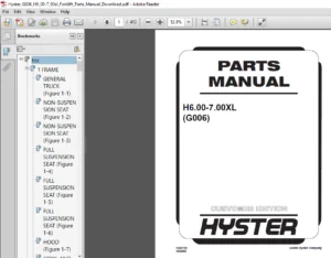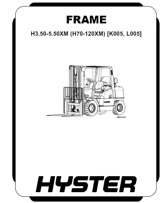
Hyster L005 (H3.50-5.50XM) Service Manual – PDF DOWNLOAD
Original price was: $98.95.$31.95Current price is: $31.95.
Hyster L005 (H3.50-5.50XM) Service Manual – PDF DOWNLOAD
PART NO. 1467898
Description
Hyster L005 (H3.50-5.50XM) Service Manual – PDF DOWNLOAD
DESCRIPTION:
PART NO. 1467898
Hyster L005 (H3.50-5.50XM) Service Manual – PDF DOWNLOAD
SAFETY PRECAUTIONS MAINTENANCE AND REPAIR:
• When lifting parts or assemblies, make sure all slings, chains, or cables are correctly
fastened, and that the load being lifted is balanced. Make sure the crane, cables, and
chains have the capacity to support the weight of the load.
• Do not lift heavy parts by hand, use a lifting mechanism.
• Wear safety glasses.
• DISCONNECT THE BATTERY CONNECTOR before doing any maintenance or repair
on electric lift trucks. Disconnect the battery ground cable on internal combustion lift
trucks.
• Always use correct blocks to prevent the unit from rolling or falling. See HOW TO PUT
THE LIFT TRUCK ON BLOCKS in the Operating Manual or the Periodic Maintenance
section.
• Keep the unit clean and the working area clean and orderly.
• Use the correct tools for the job.
• Keep the tools clean and in good condition.
• Always use HYSTER APPROVED parts when making repairs. Replacement parts
must meet or exceed the specifications of the original equipment manufacturer.
• Make sure all nuts, bolts, snap rings, and other fastening devices are removed before
using force to remove parts.
• Always fasten a DO NOT OPERATE tag to the controls of the unit whenmaking repairs,
or if the unit needs repairs.
• Be sure to follow the WARNING and CAUTION notes in the instructions.
• Gasoline, Liquid Petroleum Gas (LPG), Compressed Natural Gas (CNG), and Diesel fuel
are flammable. Be sure to follow the necessary safety precautions when handling these
fuels and when working on these fuel systems.
• Batteries generate flammable gas when they are being charged. Keep fire and sparks
away from the area. Make sure the area is well ventilated.
TABLE OF CONTENTS:
Hyster L005 (H3.50-5.50XM) Service Manual – PDF DOWNLOAD
0100SRM0726-1467898(06-2004)-EN.........................................................  1
	toc.................................................................................  1
		Frame...........................................................................  1
		Safety Precautions Maintenance and Repair.......................................  2
		General.........................................................................  5
		Description.....................................................................  5
		Counterweight Repair............................................................  5
			Remove......................................................................  5
			Install.....................................................................  6
		Hood Repair.....................................................................  6
			Remove......................................................................  6
			Install.....................................................................  6
		Overhead Guard Repair...........................................................  8
			Remove......................................................................  8
			Inspect.....................................................................  8
			Install.....................................................................  8
			LED Backup and Brake Lights, Replace........................................  8
				Remove..................................................................  8
				Install.................................................................  8
		Operator Restraint System Repair................................................  9
		Radiator Repair................................................................. 10
			Remove...................................................................... 10
			Install..................................................................... 10
		Exhaust System Repair........................................................... 12
			Muffler..................................................................... 12
				Remove.................................................................. 12
				Install................................................................. 12
			LPG/Gas Engine Exhaust Pipe - Lift Trucks Without Low Emissions............. 12
				Remove.................................................................. 12
				Install................................................................. 15
			EPA Compliant LPG/Gas Engine Exhaust System................................. 15
				Remove.................................................................. 15
				Install................................................................. 17
			Diesel Engine Exhaust Pipe.................................................. 17
				Remove.................................................................. 17
				Install................................................................. 19
		Engine Repair................................................................... 19
			Remove...................................................................... 19
			Install..................................................................... 21
		Throttle Pedal Adjustment....................................................... 23
			Perkins 1104C-44(RE) Diesel Engine.......................................... 23
				Lift Trucks With an Accelerator Pedal................................... 23
				Lift Trucks With a MONOTROL Pedal....................................... 24
		Fuel and Hydraulic Tanks Repair................................................. 26
			Inspect..................................................................... 26
			Small Leaks, Repair......................................................... 26
			Large Leaks, Repair......................................................... 26
			Clean....................................................................... 26
				Steam Method............................................................ 26
				Chemical Solution Method................................................ 27
			Other Preparation Methods for Repair........................................ 27
		Safety Labels................................................................... 27
	tables..............................................................................  1
		Table 1. Weight of Counterweights...............................................  5
0100SRM0778-147186(06-2004)-EN.......................................................... 33
	toc................................................................................. 33
		Operators Cab................................................................... 33
		Safety Precautions Maintenance and Repair....................................... 34
		General......................................................................... 37
		Cab Repair...................................................................... 38
			Remove...................................................................... 38
			Install..................................................................... 39
		Switch Panel.................................................................... 39
		Window Wipers Replacement....................................................... 40
			Front Wiper Assembly........................................................ 40
			Rear Wiper Assembly......................................................... 40
		Door Handle Assembly............................................................ 42
		Fuse Panel...................................................................... 43
		Heater Assembly................................................................. 43
			Remove...................................................................... 43
			Install..................................................................... 43
		Window Replacement.............................................................. 45
		Options......................................................................... 47
			Rear Strobe Lights.......................................................... 47
			Heavy-Duty Air Cleaner...................................................... 47
		Label Replacement............................................................... 48
		Electrical Schematics........................................................... 48
	tables.............................................................................. 33
		Table 1. Material Specifications for Cab Windows................................ 45
0600SRM590-897800(11-2003)-EN........................................................... 53
	toc................................................................................. 53
		GM Engines...................................................................... 53
		Safety Precautions Maintenance and Repair....................................... 54
		General......................................................................... 57
		Description..................................................................... 57
		Engine Removal and Installation................................................. 58
		Cylinder Head Repair............................................................ 58
			Remove and Disassemble...................................................... 58
			Clean and Inspect........................................................... 58
			Valve Guides and Seats, Repairs............................................. 59
			Valves, Repair.............................................................. 59
			Valve Seats, Repair......................................................... 60
			Valve Springs............................................................... 61
			Rocker Arm Studs (Early Models)............................................. 61
			Rocker Arm Studs (Late Models).............................................. 62
			Assemble and Install........................................................ 62
		Cylinder Block Cleaning and Inspection.......................................... 66
		Piston Bore Preparation......................................................... 66
		Engine Mounts Installation...................................................... 66
		Lubrication System Repair....................................................... 67
			Oil Pump, Remove and Disassemble............................................ 67
			Clean and Inspect........................................................... 67
			Oil Pump, Assemble and Install.............................................. 67
			Oil Sump, Install........................................................... 68
		Timing Cover, Timing Sprockets, Camshaft, and Valve Lifters..................... 69
			Timing Cover................................................................ 69
				Remove.................................................................. 69
				Install................................................................. 71
			Timing Sprockets............................................................ 71
				Remove.................................................................. 71
				Install................................................................. 71
			Camshaft.................................................................... 72
				Remove.................................................................. 72
				Inspect................................................................. 72
				Install................................................................. 72
			Balance Shaft............................................................... 73
				Remove.................................................................. 73
				Install................................................................. 74
			Hydraulic Valve Lifters..................................................... 74
				Remove.................................................................. 74
				Disassemble............................................................. 75
				Clean and Inspect....................................................... 75
				Assemble................................................................ 75
				Install................................................................. 76
		Crankshaft Repair............................................................... 77
			Remove...................................................................... 77
			Inspect and Repair.......................................................... 77
			How to Check Clearance Between Main Bearings and Their Journals............. 78
			Install..................................................................... 79
		Piston and Connecting Rod Assemblies Repair..................................... 80
			Connecting Rod Bearings, Replace............................................ 80
			Piston and Connecting Rod Assemblies, Remove................................ 81
			Disassemble................................................................. 81
			Piston, Clean and Inspect................................................... 82
			Cylinder Bores, Inspect and Repair.......................................... 82
			Piston Rings................................................................ 83
			Assemble.................................................................... 84
			Piston and Connecting Rod Assemblies, Install............................... 84
		Flywheel and Flywheel Housing Repair............................................ 85
			Flywheel, Repair............................................................ 85
			Flywheel, Install........................................................... 85
				H3.50-5.00XL (H70-110XL), S3.50-5.50XL (S70-120XL), S6.00-7.00XL........ 85
				H6.00-7.00XL (H135-155XL)............................................... 85
			Flywheel Housing H3.50-5.00XL (H70-110XL), H3.50-5.50XM (H70-120............ 85
			Engine Adapter H6.00-7.00XL (H135-155XL).................................... 85
		Coolant Pump Repair............................................................. 86
		Thermostat Replacement.......................................................... 86
		Fan Mount Repair (Early Models)................................................. 86
		Fan Mount Assembly Repair (Late Models)......................................... 86
		Drive Belt Installation......................................................... 88
		Valve Clearance Adjustment (Early Models)....................................... 89
		Valve Clearance Adjustment (New Models)......................................... 90
		Compression Check............................................................... 90
		Engine Specifications........................................................... 90
			Engine Data................................................................. 90
			Cylinder Head............................................................... 91
			Hydraulic Valve Lifter...................................................... 91
			Camshaft.................................................................... 91
			Pistons..................................................................... 91
			Crankshaft.................................................................. 92
			Connecting Rods............................................................. 93
			Balance Shaft............................................................... 93
			Cooling System.............................................................. 93
			Lubrication System.......................................................... 93
		Torque Specifications........................................................... 94
		Troubleshooting................................................................. 95
	tables.............................................................................. 53
		Table 1. Piston Rings Arrangement on Piston..................................... 84
0600SRM1070-1552002(12-2003)-EN.........................................................101
	toc.................................................................................101
		Perkins Diesel Engines..........................................................101
		Safety Precautions Maintenance and Repair.......................................102
		General.........................................................................109
			General Safety Rules........................................................109
		Description.....................................................................110
			Engine Serial Number Codes..................................................110
			Engine Data.................................................................112
		Engine Removal and Installation.................................................113
		Cylinder Head Assembly Repair...................................................113
			Engine Breather.............................................................113
				Remove..................................................................113
				Install.................................................................113
			Valve Cover.................................................................114
				Remove..................................................................114
				Install.................................................................114
			Rocker Arm Assembly.........................................................116
				Remove..................................................................116
				Disassemble.............................................................116
				Inspect.................................................................116
				Assemble................................................................116
				Install.................................................................117
			Valve Clearance Adjustments.................................................117
			Valve Springs...............................................................118
			Cylinder Head Assembly......................................................119
				Remove..................................................................119
				Inspect.................................................................120
				Install.................................................................121
			Valves and Valve Springs....................................................122
				Remove..................................................................122
				Inspect.................................................................123
				Install.................................................................123
			Valve Guides................................................................124
				Inspect.................................................................124
				Remove..................................................................124
				Install.................................................................124
			Valve Seats.................................................................126
				Inspect.................................................................126
				Repair..................................................................126
				New Valve Seats, Install................................................127
		Piston and Connecting Rod Assemblies Repair.....................................127
			General.....................................................................127
			Rod Bearings................................................................128
				Remove..................................................................128
				Install.................................................................128
			Piston and Connecting Rod Assembly..........................................129
				Service Note............................................................129
				Remove..................................................................129
				Disassemble.............................................................130
				Inspect.................................................................130
				How to Select Correct Replacements......................................131
				Assemble................................................................132
				Install.................................................................133
			Piston Cooling Jets.........................................................134
				Remove..................................................................134
				Install.................................................................135
		Crankshaft Assembly Repair......................................................135
			General.....................................................................135
			Crankshaft Pulley...........................................................135
				Remove..................................................................135
				Inspect.................................................................135
				Install.................................................................136
			Rear Oil Seal...............................................................136
				Remove..................................................................136
				Install.................................................................136
			Crankshaft Flange Wear Sleeve...............................................138
				Remove..................................................................138
				Install.................................................................138
			Main Bearings...............................................................139
				Remove..................................................................139
				Inspect.................................................................139
				Install.................................................................140
			Thrust Washers..............................................................141
				Crankshaft Axle Movement, Check.........................................141
				Remove..................................................................141
				Install.................................................................142
			Crankshaft..................................................................142
				Remove..................................................................142
				Inspect.................................................................143
				Install.................................................................143
			Crankshaft Timing Ring......................................................145
				Remove..................................................................145
				Install.................................................................145
			Flywheel....................................................................145
				Remove..................................................................145
				Ring Gear, Replace......................................................146
				Install.................................................................146
			Flywheel Housing............................................................146
				Remove..................................................................146
				Install.................................................................147
		Timing Case and Timing Gears Repair.............................................147
			General.....................................................................147
			Timing Case Cover...........................................................147
				Remove..................................................................147
				Install.................................................................148
			Front Oil Seal..............................................................149
				Remove, With Timing Case Installed......................................149
				Install, With Timing Case Installed.....................................149
				Remove, With Timing Case Removed........................................150
				Install, With Timing Case Removed.......................................150
			Crankshaft Pulley Wear Sleeve, Install......................................151
			Fuel Pump Gear..............................................................151
				Remove..................................................................151
				Install.................................................................153
			Idler Gear and Hub..........................................................154
				Remove..................................................................154
				Disassemble.............................................................155
					Standard Idler Gear and Hub Assembly................................155
					Heavy Duty Idler Gear and Hub Assembly..............................155
				Assemble................................................................155
					Standard Idler Gear and Hub Assembly................................155
					Heavy Duty Idler Gear and Hub Assembly..............................156
				Install.................................................................156
			Camshaft Gear...............................................................157
				Remove..................................................................157
				Install.................................................................157
			Crankshaft Gear.............................................................158
				Remove..................................................................158
				Install.................................................................158
			Timing Case.................................................................158
				Remove..................................................................158
				Install.................................................................159
			Power Take-Off (PTO) Adaptor................................................160
				Remove..................................................................160
				Disassemble.............................................................161
				Assemble................................................................161
				Install.................................................................161
			Camshaft and Tappets........................................................161
				Remove..................................................................161
				Install.................................................................162
		Cylinder Block Assembly Repair..................................................162
			General.....................................................................162
			Cylinder Block..............................................................163
				Disassemble.............................................................163
				Inspect.................................................................163
				Assemble................................................................163
			Cylinder Bore...............................................................164
				Inspect.................................................................164
				Cylinder Liner Condition Check..........................................164
		Engine Timing...................................................................164
			General.....................................................................164
			How to Set Number One Piston to TDC on Compression Stroke...................164
			Fuel Injection Pump Timing, Check...........................................166
			Fuel Injection Pump Timing, Adjust..........................................167
		Lubrication System Repair.......................................................168
			General.....................................................................168
			Oil Filter, Replace.........................................................168
			Oil Filter Head.............................................................169
				Remove..................................................................169
				Install.................................................................169
			Oil Sump....................................................................170
				Remove..................................................................170
				Install.................................................................170
			Oil Pump....................................................................171
				Remove..................................................................171
				Inspect.................................................................171
				Install.................................................................172
			Oil Strainer and Suction Pipe...............................................173
				Remove..................................................................173
				Install.................................................................173
			Relief Valve................................................................173
				Remove..................................................................173
				Install.................................................................173
			Dipstick Tube...............................................................174
				Remove and Install......................................................174
		Fuel System Repair..............................................................174
			General.....................................................................174
			Cold Start Advance Unit (KSB)...............................................175
			Typical Fuel System.........................................................176
			Fuel Filter.................................................................177
				Remove..................................................................177
				Install.................................................................177
			Fuel Injectors..............................................................178
				Remove..................................................................178
				Install.................................................................179
			Fuel System Air Removal.....................................................180
			Bosch EVPE Fuel Injection Pump..............................................180
				General.................................................................180
				Remove..................................................................181
				Install.................................................................182
		Cooling System Repair...........................................................182
			General.....................................................................182
			Thermostat..................................................................184
				Remove..................................................................184
				Install.................................................................184
				Test....................................................................185
			Coolant Pump................................................................185
				Remove..................................................................185
				Disassemble.............................................................186
				Assemble................................................................187
				Install.................................................................188
			Fan.........................................................................188
				Remove and Install......................................................188
			Fan Drive...................................................................189
				Remove..................................................................189
				Install.................................................................189
			Oil Cooler..................................................................189
				Remove..................................................................189
				Disassemble and Assemble................................................189
				Install.................................................................190
			Coolant By-Pass Hose........................................................190
				Removal.................................................................190
				Install.................................................................190
		Electrical Equipment Repair.....................................................190
			Drive Belt..................................................................190
				Check...................................................................190
				Adjust..................................................................191
				Remove..................................................................191
				Install.................................................................191
			Alternator..................................................................191
				Remove..................................................................191
				Install.................................................................191
				Fault Diagnosis.........................................................192
					Normal Operation:...................................................192
					If the warning lamp is not illuminated when the ignition switch ....192
					If the Warning Light Continues to be Illuminated When the Altern....193
			Starter Motor...............................................................193
				Remove..................................................................193
				Install.................................................................194
				Test....................................................................194
			Starting Aid................................................................194
				Remove..................................................................194
				Install.................................................................194
				Check...................................................................195
					Power Supply Continuity.............................................195
					Operation...........................................................195
			Pressure Sensor.............................................................196
				Remove..................................................................196
				Install.................................................................197
			Temperature Sensor..........................................................197
				Remove..................................................................197
				Install.................................................................197
		Engine Specifications...........................................................198
			Cylinder Head Assembly......................................................198
			Piston and Connecting Rods..................................................201
			Crankshaft Assembly.........................................................202
				Crankshaft Overhaul.....................................................202
			Timing Case and Drive Assembly..............................................204
			Engine Block Assembly.......................................................205
			Lubrication System..........................................................206
			Fuel System.................................................................206
			Cooling System..............................................................207
			Flywheel and Housing........................................................208
			Electrical Equipment........................................................208
		Torque Specifications...........................................................208
		Special Torque Specifications...................................................209
			Cylinder Head Assembly......................................................209
			Piston and Connecting Rod Assemblies........................................209
			Crankshaft Assembly.........................................................209
			Timing Case and Drive Assembly..............................................209
			Cylinder block..............................................................209
			Fuel System.................................................................209
			Lubrication System..........................................................209
			Cooling System..............................................................210
			Flywheel and Housing........................................................210
			Electrical Equipment........................................................210
		Special Tools...................................................................211
		Troubleshooting.................................................................214
	tables..............................................................................101
		Table 1. Cylinder Head..........................................................198
		Table 2. Valve Guides...........................................................198
		Table 3. Inlet Valves...........................................................199
		Table 4. Exhaust Valves.........................................................199
		Table 5. Valve Springs..........................................................200
		Table 6. Tappets................................................................200
		Table 7. Rocker Arm Shaft.......................................................200
		Table 8. Rocker Arms and Bushings...............................................201
		Table 9. Pistons................................................................201
		Table 10. Piston Rings..........................................................201
		Table 11. Piston Pins...........................................................201
		Table 12. Connecting Rods.......................................................201
		Table 13. Small End Bushings....................................................202
		Table 14. Connecting Rod Bearings...............................................202
		Table 15. Piston Cooling Jets...................................................202
		Table 16. Crankshaft Overhaul Specifications....................................203
		Table 17. Maximum Variation (Run-out)...........................................204
		Table 18. Camshaft..............................................................204
		Table 19. Camshaft Thrust Washer................................................204
		Table 20. Camshaft Gear.........................................................204
		Table 21. Gear for Fuel Pump....................................................204
		Table 22. Crankshaft Gear.......................................................204
		Table 23. Idler Gear and Hub....................................................205
		Table 24. Timing Gear Backlash Values...........................................205
		Table 25. Cylinder Block........................................................205
		Table 26. Oil Pump..............................................................206
		Table 27. Idler Gear for Oil Pump...............................................206
		Table 28. Relief Valve..........................................................206
		Table 29. Oil Filter............................................................206
		Table 30. Bosch Fuel Injection Pump.............................................206
		Table 31. Fuel Injector Settings................................................207
		Table 32. Fuel Pump.............................................................207
		Table 33. Fuel Filter...........................................................207
		Table 34. Coolant Pump..........................................................207
		Table 35. Thermostat............................................................207
		Table 36. Fan Drive Housing.....................................................208
		Table 37. Limits for Flywheel Run Out and Alignment (Total Indic................208
		Table 38. Alternator............................................................208
		Table 39. Starter Motor.........................................................208
		Table 40. Starting Aids.........................................................208
		Table 41. List of Possible Causes...............................................215
0700SRM740-1466271(02-2004)-EN..........................................................219
	toc.................................................................................219
		Cooling System..................................................................219
		Safety Precautions Maintenance and Repair.......................................220
		General.........................................................................223
		Description.....................................................................223
			Radiator....................................................................223
			Radiator Cap................................................................223
			Thermostat..................................................................223
			Water Pump..................................................................224
			Fan and Fan Shroud..........................................................224
			Drive Shaft.................................................................224
		Cooling System Checks...........................................................224
			Exhaust Leaks into Cooling System...........................................224
		Radiator Repair.................................................................224
			Checks......................................................................224
			Clean.......................................................................224
			Cooling System..............................................................226
				Drain...................................................................226
				Fill....................................................................226
		Water Pump Repair...............................................................226
			Checks......................................................................226
		Thermostat Repair...............................................................227
			Checks......................................................................227
		Fan Assembly Repair.............................................................227
			Remove......................................................................227
			Inspect.....................................................................227
			Install.....................................................................227
		Fan Belt Repair.................................................................230
			Remove......................................................................230
			Install.....................................................................230
		Drive Shaft Repair..............................................................230
			Remove......................................................................230
			Install.....................................................................230
		Troubleshooting.................................................................230
0900SRM745-1466265(09-2003)-EN..........................................................235
	toc.................................................................................235
		LPG Fuel System.................................................................235
		Safety Precautions Maintenance and Repair.......................................236
		General.........................................................................239
		Description and Operation.......................................................239
			Fuel Tank...................................................................239
			Fuel Filter and Fuel Valve Unit.............................................239
			LPG Convertor Vaporizer (IMPCO).............................................239
			LPG Controller (Dana EPIC/Teleflex-GFI).....................................243
				Filter Section..........................................................243
				Lock-Off Section........................................................243
				Converter Section - Primary Regulation (Stage 1)........................243
				Converter Section - Secondary Regulation (Stage 2)......................243
			Carburetor..................................................................244
			Governor....................................................................247
			Two-Way Valves, Open-Loop System............................................247
			Closed-Loop Fuel Control....................................................247
			O.E. Tune Valve, Closed-Loop Fuel System....................................248
			Oxygen Sensor, Closed-Loop Fuel System......................................248
		LPG Tank Repair.................................................................248
			Remove......................................................................248
			Install.....................................................................248
		Hydrostatic Relief Valve Repair.................................................249
			Remove and Install..........................................................249
		Filter Unit Repair..............................................................250
			Fuel Filter Element, Replace................................................250
			Diaphragm and Fuel Valve, Replace...........................................250
		Hoses Replacement...............................................................250
		LPG Convertor Vaporizer (IMPCO) Repair..........................................252
			Remove......................................................................252
			Disassemble.................................................................252
			Clean.......................................................................252
			Inspect.....................................................................252
			Assemble....................................................................254
			Install.....................................................................258
		LPG Controller (Dana EPIC/Teleflex-GFI) Repairs.................................258
			Remove......................................................................258
			Disassemble.................................................................258
				Converter Section.......................................................258
				Filter Section..........................................................260
				Lock-Off Section........................................................260
			Clean.......................................................................262
			Inspect.....................................................................262
			LPG Controller Assembly.....................................................262
				Filter Section..........................................................262
				Lock-Off Section........................................................262
				Converter Section.......................................................262
		Carburetor Repair...............................................................264
			Remove......................................................................264
			Disassemble.................................................................264
			Clean.......................................................................264
			Assemble....................................................................265
			Install.....................................................................265
		Governor Assembly Repair........................................................266
		Governor Motor Repair...........................................................268
			Remove......................................................................268
			Install.....................................................................268
		Filter Unit Check...............................................................268
		Vaporizer Check.................................................................269
			Pressure Reducer Valve......................................................269
			Vapor Valve.................................................................269
		Carburetor Adjustment...........................................................269
			Idle Mixture................................................................269
			Idle Speed..................................................................269
		Throttle Linkage Adjustment.....................................................269
		LPG Controller Adjustments (Dana EPIC/Teleflex-GFI).............................270
			Filter and Lock-Off Sections Leak Check.....................................270
			Lock-Off Section Functional Check...........................................271
			Controller Pressure Test....................................................271
			Adjustment of Secondary Lever...............................................272
			Final Adjustment Check......................................................272
		Troubleshooting.................................................................273
1300SRM0727-1466259(06-2004)-EN.........................................................283
	toc.................................................................................283
		Two-Speed Powershift Transmission...............................................283
		Safety Precautions Maintenance and Repair.......................................284
		General.........................................................................287
		Mechanical Description..........................................................287
			Torque Converter............................................................288
			Transmission Pump...........................................................288
			Shaft Assemblies............................................................288
			Input (Reverse) Shaft.......................................................288
			Counter (Forward) Clutch Shafts.............................................288
			Clutch Assemblies...........................................................288
			Output Gear and Pinion......................................................289
			Electronic Control Unit.....................................................289
		Hydraulic Operation.............................................................290
			Torque Converter............................................................290
			Seal Rings..................................................................291
		Control Valve...................................................................291
			Clutch Pressure Regulator...................................................291
			Inching Spool Assembly......................................................291
			Direction Spool.............................................................293
			Modulator Circuit...........................................................293
			Torque Converter Regulator..................................................293
		MONOTROL® Pedal.................................................................294
			MONOTROL Pedal Start Circuit................................................294
		Direction Control Lever.........................................................295
		Oil Flow Diagrams...............................................................295
			Neutral.....................................................................295
			Modulator Operation.........................................................297
			Forward-Low.................................................................300
			Forward-Low-Inching.........................................................300
			Reverse.....................................................................304
1300SRM0728-1466253(06-2004)-EN.........................................................311
	toc.................................................................................311
		Two-Speed Powershift Transmission...............................................311
		Safety Precautions Maintenance and Repair.......................................312
		General.........................................................................315
		Transmission Repair.............................................................315
			Remove......................................................................315
			Install.....................................................................315
		Clutch Packs Repair.............................................................318
			Remove and Disassemble......................................................318
				Clutch Assemblies, Disassemble..........................................321
			Inspect.....................................................................323
			Assemble and Install........................................................324
				Clutch Assemblies, Assemble and Install.................................324
		Differential Repair.............................................................332
			Remove and Disassemble......................................................332
			Inspect.....................................................................333
			Original Parts, Assemble and Install........................................333
			New Parts, Assemble and Install.............................................333
				Adjustments With Original Shim Pack.....................................334
				Adjustments Without Original Shim Pack..................................335
				Differential and Ring Gear Assembly, Assemble...........................337
		Control Valve Repair............................................................342
			Remove and Disassemble......................................................342
			Inspect.....................................................................344
			Assemble and Install........................................................344
		MONOTROL® Pedal Repair..........................................................345
			Remove and Disassemble......................................................345
			Assemble and Install........................................................345
		Direction Control Lever.........................................................348
			Remove and Disassemble......................................................348
			Assemble and Install........................................................348
		Stall Test......................................................................349
		Inching/Brake Pedal Adjustment..................................................350
		MONOTROL® Pedal Neutral Start Switch Adjustment.................................352
		MONOTROL® Pedal Neutral Start Switch Test.......................................353
			Test 1......................................................................353
			Test 2......................................................................353
		Electronic Control Unit Check...................................................354
		Oil Pressure Check..............................................................355
			Transmission Pump Relief Valve, Test Port 1, Check..........................356
			Input (Reverse) Clutch Pressure, Test Port 2, Check.........................356
			Counter (Forward) Clutch Pressure, Test Ports 3 and 4, Check................356
			Torque Converter Regulator, Test Port 5, Check..............................356
			Lubrication Circuit Oil Pressure, Test Port 6, Check........................356
			Modulator Pressure, Test Port 7, Check......................................356
		2-Speed Transmission Will Not Shift.............................................357
		Troubleshooting.................................................................358
		Troubleshooting - Pressure Tests................................................361
	tables..............................................................................311
		Table 1. Pinion Variation Numbers Examples......................................334
		Table 2. Ring and Pinion Tooth Contact Adjustment...............................340
		Table 3. Stall Speeds (New Engines).............................................349
		Table 4. Electronic Control Unit Connector......................................354
		Table 5. Transmission Pressure Port Check.......................................355
1300SRM800-1480352(03-2004)-EN..........................................................365
	toc.................................................................................365
		Hydrostatic Transmission........................................................365
		Safety Precautions Maintenance and Repair.......................................366
		General.........................................................................369
		Component Descriptions..........................................................369
			Power Unit General Arrangement..............................................369
			Hydrostatic Pump Mounting...................................................370
				Perkins 1004-42 and 1104C-44(RE) Diesel Engines.........................370
				GM 4.3L LPG Engine......................................................370
			Hydrostatic Control Components..............................................370
		Hydrostatic System Operation....................................................373
			Hydrostatic Pump............................................................374
			Drive Axle..................................................................374
			Transmission Control Module (TCM)...........................................376
				Perkins 1004-42 Diesel Engine Trucks....................................376
				Perkins 1104C-44(RE) Diesel and GM 4.3L LPG Engine Trucks...............376
				Transmission Control Inputs.............................................379
					Key Switch..........................................................379
					Forward/Reverse Switches, Perkins 1004-42 Diesel Engine Trucks......379
					Forward/Reverse Switches, Perkins 1104C-44(RE) Diesel and GM 4.3....379
					Parking Brake Switches..............................................379
					Engine Speed Sensor.................................................379
					Wheel Speed Sensors, Perkins 1104C-44(RE) Diesel and GM 4.3L LPG....382
					Brake Pressure Sensor...............................................382
					Charge Pressure Sensor..............................................382
					Transmission Oil Temperature Sensor.................................382
					Throttle Pedal Switch, Perkins 1004-42 Diesel Engine Trucks.........382
					Throttle Pedal Switch, Perkins 1104C-44(RE) Diesel and GM 4.3L L....382
					Throttle Pedal Position Sensor, Perkins 1004-42 Diesel Engine Tr....382
					Throttle Pedal Position Sensor, Perkins 1104C-44(RE) Diesel and ....384
				Transmission Control Outputs............................................384
					Forward/Reverse Solenoid Enable, Perkins 1004-42 Diesel Engine T....384
					Forward/Reverse Solenoid Enable, Perkins 1104C-44(RE) Diesel and....384
					Forward/Reverse Solenoids, Perkins 1104C-44(RE) Diesel and GM 4.....384
					Engine Start Enable.................................................384
					Fuel Cutoff Relay...................................................386
					Retard Valve........................................................386
					Pilot Solenoid Valve, Perkins 1004-42 Diesel Engine Trucks..........386
					Pilot Solenoid Valve Enable, Perkins 1104C-44(RE) Diesel and GM ....386
					Transmission Fault Warning Light....................................386
					Transmission Overspeed Warning Light................................386
					Oil Temperature Warning Light.......................................386
				Throttle-Up Inputs......................................................387
					Lift Lever Switch, Perkins 1004-42 Diesel Engine Trucks.............387
					Lift Lever Position Sensor, Perkins 1004-42 Diesel Engine Trucks....387
					Lift Lever Switch, Perkins 1104C-44(RE) and GM 4.3L LPG Engine T....387
					Lift Lever Position Sensor, Perkins 1104C-44(RE) and GM 4.3L LPG....387
					Tilt/Auxiliary Lever Switches, Perkins 1004-42 Diesel Engine Tru....387
					Tilt/Auxiliary Lever Switches, Perkins 1104C-44(RE) Diesel and G....387
					Engine Throttle Position Sensor, Perkins 1004-42 Diesel Engine T....387
				Throttle-Up Outputs, Perkins 1004-42 Diesel Engine Trucks...............388
					Throttle-Up Motor...................................................388
				Throttle Servo Motor - Perkins 1104C-44(RE) Diesel and GM 4.3L L........388
		Transmission Control Module (TCM) Operation.....................................389
			How the TCM Begins Operation................................................389
			TCM Operation on a Running Lift Truck.......................................389
				Lift Trucks With Perkins 1004-42 Diesel Engine..........................389
				Lift Trucks With Perkins 1104C-44(RE) Diesel and GM 4.3L LPG Eng........389
			Event and Fault Detection...................................................389
			Diagnostic Connector........................................................390
		Hydrostatic Transmission Features...............................................390
			Travel Control..............................................................390
				Lift Trucks With The Perkins 1004-42 Diesel Engine......................390
				Lift Trucks With the Perkins 1104C-44(RE) Diesel and GM 4.3L LPG........390
			Antistall...................................................................391
			Dynamic Braking.............................................................391
			Brake Inching...............................................................391
			Overspeed Control...........................................................391
			Hydraulic Retard............................................................392
			Wheel Anti-spin.............................................................392
			Temperature Compensation....................................................392
			Low Charge Pressure Compensation............................................393
			Quick-Roll..................................................................394
			Throttle-Up (Option)........................................................394
				Perkins 1004-42 Diesel Engine Lift Trucks Only..........................394
		Hydraulic Circuit...............................................................394
			Loop Circuit................................................................394
			Charge Circuit..............................................................397
			Pilot Supply Circuit........................................................397
			Pilot Control Circuit.......................................................397
			Retard Circuit..............................................................398
			Cooling Oil Supply Circuit..................................................398
			Cooling Circuit.............................................................398
	tables..............................................................................365
		Table 1. Electronic Transmission Control System - Perkins 1004-4................372
		Table 2. Electronic Transmission Control System - Perkins 1104C-................372
1300SRM801-1480353(03-2004)-EN..........................................................401
	toc.................................................................................401
		Hydrostatic Transmission........................................................401
		Safety Precautions Maintenance and Repair.......................................402
		General.........................................................................407
			TransLink™ User Interface Software..........................................407
				Connecting PC to TCM....................................................407
			Transmission Fluid..........................................................408
		Startup and Calibration.........................................................410
			Startup Procedure Following Service or Repairs..............................410
			Throttle System Calibration.................................................411
				Perkins 1004-42 Diesel Engine...........................................411
				Perkins 1104C-44(RE) Diesel Engine and GM 4.3L LPG Engine...............412
			Throttle System Calibration Checks..........................................412
				Perkins 1104C-44(RE) Diesel Engine and GM 4.3L LPG Engine Lift T........412
		Hydrostatic Pump Repair.........................................................413
			Remove......................................................................413
			Install.....................................................................415
		Charge Pump Repair..............................................................417
			Remove......................................................................417
			Inspect.....................................................................417
			Install.....................................................................417
		Pump Control Valve Repair.......................................................419
			Remove......................................................................419
			Inspect.....................................................................419
			Install.....................................................................419
			Replace Pilot Solenoid......................................................419
			Replace Directional Solenoid Pair...........................................419
			Clean or Replace Pilot Supply Filter Disk...................................419
			Replace Loop Relief Cartridges..............................................420
			Replace Filter Cartridge....................................................420
			Replace Filter Head.........................................................421
		Drive Axle Repair...............................................................421
			Remove and Disassemble......................................................421
			Inspect.....................................................................424
			Assemble and Install........................................................424
			Wheel Speed Sensors, Replace................................................425
				Lift Trucks With Perkins 1104C-44(RE) Diesel Engine and GM 4.3L ........425
		Axle Valve Repair...............................................................425
			Remove......................................................................425
			Inspect.....................................................................425
			Install.....................................................................425
			Replace Pressure Reducing Valve.............................................425
			Replace Shuttle Valve.......................................................426
			Replace Charge Supply Regulator.............................................426
			Replace Retard Valve........................................................426
			Replace Temperature Sensor..................................................426
		Transmission Control Module (TCM) Replacement...................................427
		Throttle Pedal/ MONOTROL® Pedal Repair..........................................427
			Remove Standard Throttle Pedal..............................................427
			Install Standard Throttle Pedal.............................................427
				Lift Trucks With Perkins 1004-42 Diesel Engine..........................427
				Lift Trucks With Perkins 1104C-44 (RE) Diesel Engine and GM 4.3L........428
			Remove and Disassemble MONOTROL Pedal.......................................428
			Assemble and Install MONOTROL Pedal.........................................428
			Replace Throttle Pedal Position Sensor......................................430
			Replace Throttle Pedal Switch...............................................431
		Throttle-Up Assembly Replace - Perkins 1004-42 Diesel Engine....................432
			Remove......................................................................432
			Inspect.....................................................................432
			Install.....................................................................432
			Replace Throttle Motor......................................................433
			Replace Engine Throttle Position Sensor.....................................433
		Throttle Servo Motor Replace - Perkins 1104C-44(RE) Diesel and G................433
			Remove......................................................................433
				Perkins 1104C-44(RE) Diesel Engine......................................433
				GM 4.3L LPG Engine......................................................433
			Inspect.....................................................................435
			Install.....................................................................435
				Perkins 1104C-44(RE) Diesel Engine......................................435
				GM 4.3L LPG Engine......................................................435
		Throttle-Up Switch Assembly Repair..............................................437
			Remove......................................................................437
			Install.....................................................................437
			Replace Lift Lever Position Sensor..........................................437
			Replace Throttle-Up Switches................................................437
		Hydrostatic Drive Checks and Adjustments........................................438
			Swashplate Positioning Cylinder.............................................438
			Truck Travel Speed Limit Adjustment.........................................439
				Perkins 1004-42 Diesel Engine...........................................439
				Perkins 1104C-44(RE) Diesel Engine and GM 4.3L LPG Engine...............439
			Charge Pressure.............................................................439
			Pilot Supply Pressure.......................................................440
			Pilot Pressure..............................................................440
			POR Pressure................................................................440
			Loop Pressure...............................................................440
		Throttle Pedal/ MONOTROL Pedal Checks and Adjustments...........................441
			Throttle Cable..............................................................441
				Perkins 1004-42 Diesel Engine Trucks....................................441
			Pedal Stop..................................................................441
				Standard Throttle Pedal.................................................441
					Perkins 1004-42 Diesel Engine Trucks................................441
					Perkins 1104C-44(RE) Diesel and GM 4.3L LPG Engine Trucks...........441
				MONOTROL Pedal..........................................................441
					Perkins 1004-42 Diesel Engine Trucks................................441
					Perkins 1104C-44(RE) Diesel and GM 4.3L LPG Engine Trucks...........441
			MONOTROL Pedal Operation....................................................441
			Throttle Pedal Position Sensor..............................................441
			Throttle Pedal Switch.......................................................442
			MONOTROL Pedal Switch.......................................................443
		Throttle-Up Assembly Checks and Adjustments.....................................444
			Engine Throttle Position Sensor.............................................444
			Throttle-Up Motor...........................................................445
		Throttle Servo Motor Checks and Adjustments.....................................445
			Throttle Servo Motor Position Sensor........................................445
			Throttle Servo Motor........................................................446
		Throttle-Up Switch Assembly Checks and Adjustments..............................447
			Throttle-Up Switches........................................................447
			Lift Lever Position Sensor..................................................447
		Sensor Checks...................................................................448
			Charge Pressure Sensor......................................................448
			Brake Pressure Sensor.......................................................448
			Oil Temperature Sensor......................................................449
			Engine Speed Sensor.........................................................449
				Left Speed Sensor.......................................................450
				Right Speed Sensor......................................................451
		Event Codes.....................................................................451
			Perkins 1004-42 Diesel Engine Trucks........................................451
			Event Code Descriptions - Perkins 1004-42 Diesel Engine Trucks..............452
			Perkins 1104C-44(RE) Diesel Engine and GM 4.3L LPG Trucks...................458
			Event Code Descriptions - Perkins 1104C-44(RE) Diesel and GM 4.3............459
		Troubleshooting.................................................................468
			Perkins 1004-42 diesel engine trucks only...................................472
			Perkins 1004-42 diesel engine trucks only...................................473
			Perkins 1104C-44(RE) diesel and GM 4.3L LPG engine trucks...................473
			Perkins 1104C-44(RE) diesel and GM 4.3L LPG engine trucks...................473
	tables..............................................................................401
		Table 1. Charge and Brake Sensor Outputs........................................449
		Table 2. Oil Temperature Sensor Outputs.........................................449
		Table 3. Engine Speed Sensor Outputs............................................450
		Table 4. Wheel Speed Sensor Outputs - Perkins 1104C-44(RE) Diese................450
1400SRM731-1466247(09-2003)-EN..........................................................479
	toc.................................................................................479
		Drive Axle......................................................................479
		Safety Precautions Maintenance and Repair.......................................480
		General.........................................................................483
		Description.....................................................................483
		Drive Axle Repair...............................................................483
			Remove and Disassemble......................................................483
			Clean and Inspect...........................................................485
			Assemble and Install........................................................485
		Troubleshooting.................................................................487
1600SRM732-1466241(10-2003)-EN..........................................................491
	toc.................................................................................491
		Steering Control Unit...........................................................491
		Safety Precautions Maintenance and Repair.......................................492
		General.........................................................................495
		Description.....................................................................495
		Operation.......................................................................495
		Steering Wheel and Column Assembly Repair.......................................497
			Remove and Disassemble......................................................497
			Assemble and Install........................................................497
			Steering Control Unit.......................................................500
				Disassemble.............................................................500
				Clean...................................................................502
				Assemble................................................................503
		System Air Removal..............................................................506
		Troubleshooting.................................................................506
1600SRM733-1466235(09-2003)-EN..........................................................511
	toc.................................................................................511
		Steering Axle...................................................................511
		Safety Precautions Maintenance and Repair.......................................512
		General.........................................................................515
		Description.....................................................................515
		Steering Axle Assembly Repair...................................................516
			Remove......................................................................516
			Install.....................................................................516
		Wheels and Hub Repair...........................................................517
			Remove and Disassemble......................................................517
			Clean.......................................................................517
			Inspect.....................................................................517
			Assemble and Install........................................................517
		Spindles and Bearings Repair....................................................518
			Remove......................................................................518
			Clean.......................................................................518
			Inspect.....................................................................518
			Assemble and Install........................................................518
		Tie Rods Repair.................................................................519
			Remove......................................................................519
			Clean.......................................................................519
			Inspect.....................................................................519
			Install.....................................................................519
		Steering Cylinder Repair........................................................519
			Remove and Disassemble......................................................519
			Clean and Inspect...........................................................520
			Assemble and Install........................................................520
		Troubleshooting.................................................................521
1800SRM734-1466229(03-2004)-EN..........................................................525
	toc.................................................................................525
		Brake System....................................................................525
		Safety Precautions Maintenance and Repair.......................................526
		General.........................................................................529
		Description and Operation.......................................................529
			Brake Booster and Master Cylinder...........................................529
			Service Brake Assembly......................................................529
			Parking Brake...............................................................530
		Brake Shoe Assemblies Repair....................................................530
			Remove and Disassemble......................................................530
			Clean.......................................................................533
			Inspect.....................................................................533
			Assemble and Install........................................................533
		Brake Booster and Master Cylinder Repair........................................535
			Remove......................................................................535
			Disassemble.................................................................535
			Clean and Inspect...........................................................535
			Assemble....................................................................535
			Install.....................................................................537
			Brake Booster Filter, Replace...............................................538
		Parking Brake Repair............................................................538
			Remove and Disassemble......................................................538
			Assemble and Install........................................................538
		Brake System Air Removal........................................................538
		Brake Pedal Adjustment..........................................................539
		Parking Brake Adjustment........................................................539
		Parking Brake Not Applied Switch Test...........................................540
		Parking Brake Switch Test ( MONOTROL® Pedal Only)...............................540
		Brake Shoes Adjustment..........................................................541
		Troubleshooting.................................................................541
1900SRM743-1466217(10-2003)-EN..........................................................547
	toc.................................................................................547
		Hydraulic System................................................................547
		Safety Precautions Maintenance and Repair.......................................548
		General.........................................................................551
		Description.....................................................................551
		Operation.......................................................................553
			Hydraulic Pump H3.50-5.50XM (H70-120XM).....................................553
			Hydraulic Pump S3.50-5.50XM (S70-120XM).....................................553
			Main Control Valve..........................................................554
			Steering Control Unit.......................................................554
		Specifications..................................................................555
			Hydraulic System Capacity...................................................555
			Hydraulic Tank Capacity.....................................................555
			Relief Pressures @ 2200 rpm, 50 to 80 C ( 120 to 180 F).....................555
			Hydraulic Pump Flow to Valve................................................555
			Steering Priority Flow......................................................555
		Troubleshooting.................................................................556
			Lift, Lower and Tilt Circuit................................................556
			Steering Circuit............................................................557
1900SRM753-1466223(09-2003)-EN..........................................................561
	toc.................................................................................561
		Hydraulic Gear Pump.............................................................561
		Safety Precautions Maintenance and Repair.......................................562
		General.........................................................................565
		Description.....................................................................565
		Operation.......................................................................565
		Hydraulic Gear Pump Repair......................................................566
			Remove......................................................................566
			Disassemble.................................................................566
			Clean.......................................................................566
			Inspect.....................................................................568
			Assemble....................................................................568
			Install.....................................................................569
		Pump Output Check...............................................................570
			Method No. 1................................................................570
			Method No. 2................................................................571
		Hydraulic System Air Check......................................................572
		Troubleshooting.................................................................572
2000SRM754-1466211(12-2003)-EN..........................................................577
	toc.................................................................................577
		Main Control Valve..............................................................577
		Safety Precautions Maintenance and Repair.......................................578
		General.........................................................................581
		Description.....................................................................581
		Operation.......................................................................581
			Lift Section................................................................581
			Tilt and Auxiliary Sections.................................................585
				Reattaching the Clevis End of the Tilt Spool............................586
			Relief Valve................................................................586
		Main Control Valve Repair.......................................................586
			Remove and Disassemble......................................................586
			Clean and Inspect...........................................................588
			Assemble....................................................................590
			Install.....................................................................590
		Pressure Relief Valve Check and Adjustment......................................591
			Main Relief Valve (Lift)....................................................591
			Steering Relief Valve.......................................................591
			Secondary Relief Valve (Tilt and Auxiliary).................................594
		Specifications..................................................................595
		Troubleshooting.................................................................595
2100SRM735-1466205(09-2003)-EN..........................................................601
	toc.................................................................................601
		Tilt Cylinders..................................................................601
		Safety Precautions Maintenance and Repair.......................................602
		General.........................................................................605
		Description.....................................................................605
		Tilt Cylinder Repair............................................................605
			Remove......................................................................605
			Disassemble.................................................................606
			Clean.......................................................................607
			Inspect.....................................................................607
			Assemble....................................................................607
			Install.....................................................................607
		Tilt Cylinder Leak Check........................................................608
		Tilt Cylinder Stroke and Mast Tilt Angle Adjustment.............................608
		Troubleshooting.................................................................608
2200SRM002-899784(10-2003)-EN...........................................................613
	toc.................................................................................613
		Alternator with Regulator.......................................................613
		Safety Precautions Maintenance and Repair.......................................614
		General.........................................................................617
		Description.....................................................................617
		Alternator Repair...............................................................619
			Alternator Type A...........................................................619
				Remove and Disassemble..................................................619
				Clean...................................................................620
				Assemble................................................................621
				Install.................................................................621
			Alternator Type B...........................................................624
				Remove and Disassemble..................................................624
				Clean...................................................................624
				Assemble................................................................625
				Install.................................................................626
		General Check and Adjustment....................................................627
		Low Output Check (Type A or Type B).............................................627
		High Output Check (Type A or Type B)............................................629
		Brushes Circuit Check...........................................................630
			Delco Alternators...........................................................630
			Motorola Alternators........................................................631
		Diodes Check....................................................................632
		Diode Bridge Check..............................................................632
			Delco and Leece-Neville Alternators.........................................632
			Motorola Alternators........................................................632
		Rotor Field Winding Check.......................................................633
		Stator Windings Check...........................................................634
		Voltage Regulator Check.........................................................634
		Troubleshooting.................................................................634
2200SRM744-1466175(09-2003)-EN..........................................................639
	toc.................................................................................639
		Carbureted Engine Management System (CEMS)......................................639
		Safety Precautions Maintenance and Repair.......................................640
		Description.....................................................................643
		Ignition Control System.........................................................644
			Setting Timing Reference....................................................644
			Idle Speed Control System...................................................644
			Curb Idle Setting Procedure.................................................645
		Governor Control System.........................................................645
		Closed-Loop Fuel System.........................................................646
			Closed-Loop Fuel Control....................................................646
			Entering Closed-Loop Control................................................646
			Normal Closed-Loop Operation................................................646
			Closed-Loop Diagnostics.....................................................646
			O.E. Tune Valve Action at Engine Shutdown...................................646
		Diagnostic System...............................................................647
			Closed-Loop Diagnostic Troubleshooting......................................648
			Diagnostic Troubleshooting..................................................648
	tables..............................................................................639
		Table 1. Diagnostic Codes.......................................................647
		Table 2. Diagnostic Troubleshooting.............................................648
2200SRM755-1466193(11-2001)-EN..........................................................657
	toc.................................................................................657
		Starter.........................................................................657
		Safety Precautions Maintenance and Repair.......................................658
		General.........................................................................661
		Description.....................................................................661
			Yoke Assembly...............................................................662
			Armature Assembly...........................................................662
			Clutch Assembly.............................................................662
			Magnetic Switch Assembly....................................................662
		Operation.......................................................................662
		Starter Repair..................................................................663
			Remove......................................................................663
			Disassemble.................................................................664
			Clean.......................................................................667
			Assemble....................................................................668
			Install.....................................................................671
		General Checks and Adjustments..................................................671
		Armature Tests..................................................................672
			Armature Short Circuit Test.................................................672
			Armature Winding Ground Test................................................672
			Commutator Run-Out Test.....................................................672
		Yoke Test.......................................................................673
		Brush and Brush Holder Check....................................................673
			Brush Holder Insulation Test................................................673
			Clutch Test.................................................................673
		Magnetic Switch Test............................................................674
			Pull-In Test................................................................674
			Hold-In Test................................................................674
			Return Test.................................................................674
		Performance Tests...............................................................675
			No-Load Test................................................................675
		Troubleshooting.................................................................675
2200SRM756-1468474(11-2003)-EN..........................................................681
	toc.................................................................................681
		Instrument Panel Indicators and Senders.........................................681
		Safety Precautions Maintenance and Repair.......................................682
		General.........................................................................685
		Description.....................................................................685
			Instruments and Senders.....................................................685
			Password Function...........................................................692
				Supervisor Password Function............................................692
					Entering Operator Passwords.........................................692
					Deleting Operator Passwords.........................................693
					Retrieve the Most Recent Operator Password Used to Enable the Tr....693
					Display All Operator Passwords Programmed Into the System...........693
					Enable and Disable Operator Passwords Function......................693
					Allow Supervisor Password to Enable the Truck to Start..............693
				Operator Passwords Function.............................................693
		Component Replacement - General Information.....................................694
		Sender Replacement..............................................................694
			Fuel Level Sender...........................................................694
			Pressure and Temperature Sender.............................................695
		Display Panel Replacement.......................................................696
		Specifications..................................................................698
		Troubleshooting.................................................................699
	tables..............................................................................681
		Table 1. Instrument Panel Description...........................................686
		Table 2. Sender Description.....................................................691
		Table 3. Meter and Sender Specifications........................................698
4000SRM736-1466163(10-2003)-EN..........................................................703
	toc.................................................................................703
		Masts...........................................................................703
		Safety Precautions Maintenance and Repair.......................................704
		General.........................................................................707
		Description and Operation.......................................................707
			Carriages...................................................................707
			Two-Stage Mast With Limited Free-Lift.......................................707
			Two-Stage Mast With Full Free-Lift..........................................708
			Three-Stage Mast With Full Free-Lift........................................709
		Safety Procedures When Working Near Mast........................................711
		Fork Replacement................................................................713
			Remove......................................................................714
			Install.....................................................................714
		Carriage Repair.................................................................715
			Remove......................................................................715
		Sideshift Carriage Repair.......................................................716
			Remove......................................................................716
			Disassemble.................................................................716
			Assemble....................................................................716
			Install.....................................................................717
		Two-Stage Mast With Limited Free-Lift Repair....................................718
			Remove - H3.50-5.50XM (H70-120XM) Model Lift Trucks.........................718
			Remove - S3.50-5.50XM (S70-120XM) and E3.50-5.50XL 3 (E70-120XL ............718
			Disassemble.................................................................718
			Clean and Inspect...........................................................722
			Assemble....................................................................723
			Install - H3.50-5.50XM (H70-120XM) Lift Truck Models........................724
			Install - S3.50-5.50XM (S70-120XM) and E3.50-5.50XL 3 (E70-120XL............726
		Two-Stage Mast With Full Free-Lift Repair.......................................728
			Remove......................................................................728
			Disassemble.................................................................728
			Clean and Inspect...........................................................730
			Assemble....................................................................730
			Install.....................................................................730
		Three-Stage Mast With Full Free-Lift Repair.....................................732
			Remove......................................................................732
			Disassemble.................................................................732
			Clean and Inspect...........................................................735
			Assemble....................................................................735
			Install.....................................................................737
		Mast Operation Check............................................................741
		Lift and Tilt System Leak Check.................................................741
			Lift System.................................................................741
			Tilt System.................................................................742
		Tilt Cylinder Stroke and Backward Tilt Angle Adjustment.........................743
		Lift Chain Adjustments..........................................................744
		Mast Adjustments................................................................747
		Carriage Adjustment.............................................................749
		Troubleshooting.................................................................749
	tables..............................................................................703
		Table 1. Tilt Cylinder Leak Check Specifications, S3.50-5.50XM (................743
		Table 2. Hook type Carriage Chain Adjustment....................................745
		Table 3. Pin-Type Carriage Chain Adjustment.....................................745
4000SRM741-1466169(10-2003)-EN..........................................................755
	toc.................................................................................755
		Lift Cylinders..................................................................755
		Safety Precautions Maintenance and Repair.......................................756
		Safety Procedures When Working Near Mast........................................759
		General.........................................................................761
		Description.....................................................................761
			Lowering Control Valve (Velocity Fuse)......................................761
		Lift Cylinder Repair............................................................764
			Remove......................................................................764
			Disassemble.................................................................765
			Assemble....................................................................765
			Install.....................................................................766
		Lift System Leak Check..........................................................766
		Troubleshooting.................................................................767
8000SRM231-910442(03-2004)-EN...........................................................771
	toc.................................................................................771
		Metric and Inch (SAE) Fasteners.................................................771
		Safety Precautions Maintenance and Repair.......................................772
		General.........................................................................775
			Threaded Fasteners..........................................................775
			Nomenclature, Threads.......................................................775
			Strength Identification.....................................................776
			Cotter (Split) Pins.........................................................776
			Fastener Torque Tables......................................................781
			Conversion Table............................................................783
	tables..............................................................................771
		Table 1. Bolts and Screws.......................................................777
		Table 2. Studs and Nuts.........................................................778
		Table 3. Torque Nuts............................................................779
		Table 4. Torque Nuts With Nylon Insert..........................................780
		Table 5. Torque Values for Metric Fasteners*....................................781
		Table 6. Torque Values for Inch Fasteners*......................................782
		Table 7. Conversion Table for Metric and English Units..........................783
		Table 8. Cotter Pin Dimensional Data............................................784
		Table 9. Cotter Pin Dimensional Data............................................785
		Table 10. Cotter Pin Dimensional Data...........................................786
		Table 11. Cotter Pin Dimensional Data...........................................788
8000SRM737-1467763(03-2004)-EN..........................................................791
	toc.................................................................................791
		Periodic Maintenance............................................................791
		Safety Precautions Maintenance and Repair.......................................792
		General.........................................................................797
			Serial Number Data..........................................................797
			How to Move Disabled Lift Truck.............................................797
				How to Tow Lift Truck...................................................797
			How to Put Lift Truck on Blocks.............................................798
				How to Raise Drive Tires................................................798
				How to Raise Steering Tires.............................................798
		Maintenance Schedule............................................................799
		Maintenance Procedures Every 8 Hours or Daily...................................813
			How to Make Checks With Engine Stopped......................................813
				Engine Oil..............................................................814
				Hydraulic System Oil....................................................814
				Cooling System..........................................................815
				Heavy Duty Precleaner...................................................815
				Fuel System.............................................................816
				Battery.................................................................816
				Tires and Wheels........................................................816
				Forks...................................................................817
					Adjust..............................................................818
					Hook Fork, Remove...................................................818
					Hook Fork, Install..................................................818
				Forks, Mast, and Lift Chains, Inspect...................................819
				Operator Restraint System...............................................820
				Safety Labels...........................................................820
			How to Make Checks With Engine Running......................................821
				Gauges, Lights, Horn, and Fuses.........................................821
				Engine Oil Pressure.....................................................821
				Cooling System..........................................................824
				Powershift Transmission Oil Level Check.................................824
				Hydrostatic Transmission Oil Level Check................................825
				Control Levers and Pedals...............................................825
				Lift System Operation...................................................825
				Inching/Brake Pedal.....................................................826
				Service Brakes..........................................................826
				Parking Brake...........................................................826
				Steering System.........................................................826
		Maintenance Procedures Every 250 Hours or 6 Weeks...............................827
			Engine Oil and Filter, GM V-6 EPA Compliant Engine (Americas Onl............827
			Air Filter, GM V-6 EPA Compliant Engine.....................................827
		Maintenance Procedures Every 500 Hours or 2 Months..............................828
			Lift Chains Lubrication.....................................................828
			Air Filter..................................................................828
			Hydraulic Pump Drive Shaft..................................................828
			Engine Oil and Filter, Diesel and GM V-6 (European Only)....................828
			Drive Belts.................................................................829
				Fan Drive Belts.........................................................829
			Perkins Diesel Engine.......................................................829
				Alternator Drive Belt...................................................829
			GM 4.3L Engine..............................................................830
				Serpentine Drive Belt...................................................830
			Hydraulic Tank Breather, Clean and Check....................................831
			Hydrostatic Transmission Filter.............................................831
				Filter Cartridge, Replace...............................................831
				Filter Head, Replace....................................................831
			Brake Fluid.................................................................832
			Lift Chains Wear Check......................................................832
			Forks, Wear and Damage Check................................................833
			Mast, Lubrication...........................................................833
			Control Levers and Pedals, Lubrication......................................834
			Steering Axle, Lubrication..................................................834
			Fuel System, Checks and Adjustments.........................................834
				LPG Carburetor..........................................................834
				Fuel Injection (Perkins Engine).........................................834
				GM V-6 Engine...........................................................834
			Cooling System, Clean Debris from Radiator Core.............................834
		Maintenance Procedures Every 1000 Hours or 6 Months.............................835
			PCV Valve, GM V-6...........................................................835
			Crankcase Breather, GM-V6...................................................835
			Spark Plug Replacement......................................................835
				Remove..................................................................835
				Install.................................................................835
			Valve Clearance, Check and Adjust...........................................835
			Water Separator, Diesel Engine..............................................836
			Fuel Filter, Replace (Diesel Engine)........................................836
			Fuel System Air Removal, Perkins (1004.42 Diesel Engine)....................836
				Differential and Drive Axle.............................................838
			Cooling System, GM V-6 EPA Compliant Engine.................................838
			LPG Fuel Filter GM V-6 EPA Compliant Engine, Replace........................838
			Inspect Engine Electrical System, Connectors, and FCVS Connectio............839
		Maintenance Procedures Every 2000 Hours or Yearly...............................839
			Differential Thrust Screw...................................................839
			Hydraulic System............................................................840
				Hydraulic Oil and Filter, Replace.......................................840
			Powershift Transmission Oil and Filter, Replace.............................841
			Hydrostatic Transmission Oil and Filter, Replace............................841
			Cooling System..............................................................842
			Wheel Bearings..............................................................842
				Steering Wheels, Lubrication............................................842
				Drive Wheels, Lubrication...............................................842
			PCV Valve, GM V-6...........................................................842
			Service Brakes..............................................................842
			Brake Booster Filter, Replace...............................................843
			LPG Filter, Replace (Pre-2004)..............................................843
			Gasoline Fuel Filter, Replace...............................................843
			Operator Restraint System...................................................843
			Oxygen Sensor (Pre 2004)....................................................844
			Oxygen Sensor GM V-6 EPA Compliant Engine...................................844
			Air Filter Element, GM V-6 EPA Compliant Engine.............................844
			Inspect Low Pressure Regulator (LPR) for Oil Buildup and Leaks..............844
			Check Throttle Shaft for Sticking...........................................845
			Inspect Exhaust Manifold and Piping for Leaks...............................845
			Test LPG/GAS Regulator Pressure.............................................845
		Safety Procedures When Working Near Mast........................................846
		Lift Chain Adjustments..........................................................848
		Fuel Injectors Repair...........................................................849
		Lift and Tilt System Leak Check.................................................850
			Lift Cylinders, Leak Check..................................................850
			Tilt Cylinders, Leak Check..................................................850
		Welding Repairs.................................................................851
		Overhead Guard Changes..........................................................851
		Wheel and Tire Replacement......................................................852
			Remove Wheels From Lift Truck...............................................852
			Remove Wheel From Tire......................................................853
				Remove Tire From Two-Piece Wheel........................................854
				Remove Tire From Three- and Four-Piece Wheel............................856
			Install Wheel in Tire.......................................................857
				Install Tire on Three- or Four-Piece Wheel..............................858
				Install Tire in Two-Piece Wheel.........................................859
			Add Air to Tires............................................................860
			Wheels, Install.............................................................860
		Dual Drive Wheels Installation..................................................860
		Solid Rubber Tire Repair........................................................861
			Wheel, Tire Remove..........................................................861
			Wheel, Tire Install.........................................................863
			SIT Tire, Change for H3.50-5.50XM (European Trucks Only)....................864
				Remove SIT Solid Tire From Wheel........................................865
				Install SIT Solid Tire on Wheel.........................................866
		Adhesives and Sealants..........................................................867
		Hydraulic Oil, Lubricant, and Coolant Specifications............................868
	tables..............................................................................791
		Table 1. Maintenance Schedule...................................................803
		Table 2. Hook-Type Carriage Chain Adjustment....................................848
		Table 3. Pin-Type Carriage Chain Adjustment.....................................849
8000SRM738-1467764(05-2004)-EN..........................................................871
	toc.................................................................................871
		Capacities and Specifications...................................................871
		Safety Precautions Maintenance and Repair.......................................872
		Lift Truck Weights..............................................................875
		Electrical System...............................................................875
		Stall Speeds....................................................................875
		Capacities......................................................................876
		Tire Pressure...................................................................876
		Engine Specifications...........................................................877
		Transmission Oil Pressures......................................................878
		Hydraulic System................................................................879
		Mast Speeds.....................................................................880
		Torque Specifications...........................................................880
			Brake System................................................................880
			Differential................................................................880
			Drive Axle..................................................................881
			Engine, GM V-6 4.3 Liter....................................................881
			Engine, Perkins 1004-42.....................................................882
			Frame.......................................................................882
			Lift Cylinders..............................................................882
			Main Control Valve..........................................................882
			Masts.......................................................................882
			Powershift Transmission.....................................................883
			Steering System.............................................................883
			Tilt Cylinders..............................................................883
			Hydrostatic Components......................................................883
	tables..............................................................................871
		Table 1. Single-Speed...........................................................878
		Table 2. Two-Speed..............................................................878
		Table 3. Hydrostatic Transmission...............................................879
8000SRM757-1467765(05-2004)-EN..........................................................887
	toc.................................................................................887
		Diagrams........................................................................887
		Safety Precautions Maintenance and Repair.......................................888
HYSTER L005 (H3.50-5.50XM) SERVICE MANUAL – PDF DOWNLOAD:
IMAGES PREVIEW OF THE MANUAL:
PLEASE NOTE:
- This is the SAME MANUAL used by the dealerships to diagnose your vehicle
- No waiting for couriers / posts as this is a PDF manual and you can download it within 2 minutes time once you make the payment.
- Your payment is all safe and the delivery of the manual is INSTANT – You will be taken to the DOWNLOAD PAGE.
- So have no hesitations whatsoever and write to us about any queries you may have : heydownloadss @gmail.com
S.V