Trusted Business
Verified & Licensed
Virus Free Files
100% Safe Downloads
Secure Payment
SSL Protected
Instant Delivery
Available Immediately
Sale!
Hyster S135XL2 S155XL2 (C024) Parts Manual – PDF DOWNLOAD
Original price was: $89.95.$29.95Current price is: $29.95.
Hyster S135XL2 S155XL2 (C024) Parts Manual – PDF DOWNLOAD
Instant PDF Download
Available immediately
Save to Your Device
Download & keep forever
Antivirus Scanned
100% virus-free
Trusted Worldwide
175,000+ customers
Description
Hyster S135XL2 S155XL2 (C024) Parts Manual – PDF DOWNLOAD
TABLE OF CONTENTS:
Hyster S135XL2 S155XL2 (C024) Parts Manual – PDF DOWNLOAD
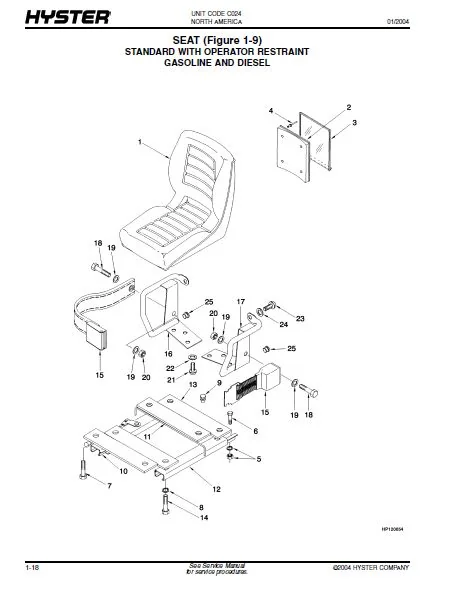
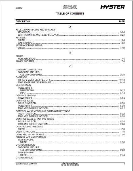
toc..................................................................  1
	1 FRAME.......................................................... 19
		GENERAL TRUCK (Figure 1-1)................................... 22
		LABELS (Figure 1-2).......................................... 24
		COWL AND FLOOR PLATES (Figure 1-3)........................... 26
		HOOD (Figure 1-4)............................................ 28
		COUNTERWEIGHT (Figure 1-5)................................... 30
		OVERHEAD GUARD (Figure 1-6).................................. 32
		LOAD BACKREST EXTENSION (Figure 1-7)......................... 34
		FORK (Figure 1-8)............................................ 36
		SEAT (Figure 1-9)............................................ 38
		SEAT (Figure 1-10)........................................... 40
		FULL SUSPENSION SEAT (Figure 1-11)........................... 42
		FULL SUSPENSION SEAT (Figure 1-12)........................... 44
		SEAT MOUNTING (Figure 1-13).................................. 46
	2 ENGINE ASSEMBLY................................................ 47
		RADIATOR (Figure 2-1)........................................ 52
		FAN DRIVE AND ALTERNATOR MOUNTING (Figure 2-2)............... 54
		COOLING AND FAN DRIVE (Figure 2-3)........................... 56
		EXHAUST GAS AND LPG (Figure 2-4)............................. 58
		EXHAUST DIESEL (Figure 2-5).................................. 60
		EXHAUST GAS AND LPG (Figure 2-6)............................. 62
		EXHAUST DIESEL (Figure 2-7).................................. 64
		EXHAUST MANIFOLD (Figure 2-8)................................ 66
		ENGINE MOUNTING (Figure 2-9)................................. 68
		ENGINE ASSEMBLY (Figure 2-10)................................ 70
		ENGINE ASSEMBLY (Figure 2-11)................................ 72
		FLYWHEEL AND HOUSING (Figure 2-12)........................... 74
		CYLINDER BLOCK (Figure 2-13)................................. 76
		CAMSHAFT AND OIL PAN (Figure 2-14)........................... 78
		VALVE COVER AND INLET MANIFOLD (Figure 2-15)................. 82
		INTAKE MANIFOLD AND FUEL RAIL (Figure 2-16).................. 86
		CYLINDER HEAD (Figure 2-17).................................. 88
		OIL PUMP (Figure 2-18)....................................... 90
		CYLINDER BLOCK (Figure 2-19)................................. 92
		CYLINDER HEAD AND INDUCTION MANIFOLD (Figure 2-20)........... 94
		VALVE COVER AND ROCKER ARM SHAFT (Figure 2-21)............... 96
		CRANKSHAFT AND PISTONS (Figure 2-22)......................... 98
		OIL PAN AND PUMP (Figure 2-23)...............................100
		WATER PUMP AND OUTLET (Figure 2-24)..........................102
		TIMING GEAR (Figure 2-25)....................................104
		EXHAUST MANIFOLD (Figure 2-26)...............................106
		OIL FILTER (Figure 2-27).....................................108
		OIL COOLER (Figure 2-28).....................................110
		FUEL INJECTION PUMP (Figure 2-29)............................112
		DRIVE ADAPTOR (Figure 2-30)..................................114
	3 FUEL SYSTEM....................................................117
		AIR FILTER (Figure 3-1)......................................120
		AIR FILTER (Figure 3-2)......................................122
		FUEL SUPPLY SYSTEM (Figure 3-3)..............................124
		FUEL SUPPLY SYSTEM (Figure 3-4)..............................126
		ENGINE FUEL SUPPLY (Figure 3-5)..............................128
		FUEL SUPPLY SYSTEM (Figure 3-6)..............................130
		THROTTLE BODY AND LPG MIXER (Figure 3-7).....................134
		LPG REGULATOR (Figure 3-8)...................................136
		THROTTLE BODY ASSEMBLY (Figure 3-9)..........................138
		THROTTLE LINKAGE (Figure 3-10)...............................140
		ACCELERATOR PEDAL AND BRACKET (Figure 3-11)..................142
		ACCELERATOR PEDAL AND BRACKET (Figure 3-12)..................144
		MONOTROL PEDAL (Figure 3-13).................................146
	4 ELECTRICAL SYSTEM..............................................149
		INSTRUMENT PANEL (Figure 4-1)................................152
		ELECTRICAL (Figure 4-2)......................................156
		ELECTRICAL (Figure 4-3)......................................158
		ELECTRICAL SYSTEM (Figure 4-4)...............................160
		ALTERNATOR MOUNTING (Figure 4-5).............................162
		STARTER MOTOR (Figure 4-6)...................................164
		STARTER MOTOR (Figure 4-7)...................................166
		DISTRIBUTOR ASSEMBLY (Figure 4-8)............................168
		GAUGE CLUSTER (Figure 4-9)...................................170
		WIRE HARNESS (ENGINE) (Figure 4-10)..........................172
		WIRE HARNESS (Figure 4-11)...................................174
		WIRE HARNESS (Figure 4-12)...................................176
		WIRE HARNESS (Figure 4-13)...................................177
		WIRE HARNESS (Figure 4-14)...................................178
		WIRE HARNESS (Figure 4-15)...................................180
		WIRE HARNESS (Figure 4-16)...................................182
	5 TRANSMISSION...................................................183
		TORQUE CONVERTER (Figure 5-1)................................186
		FLYWHEEL HOUSING (Figure 5-2)................................188
		TRANSMISSION (Figure 5-3)....................................190
		TRANSMISSION GEARS (Figure 5-4)..............................194
		CLUTCH PACK (Figure 5-5).....................................196
		CLUTCH PACK (Figure 5-6).....................................198
		DRIVE AXLE (Figure 5-7)......................................200
		UNIVERSAL JOINT (Figure 5-8).................................202
		DIFFERENTIAL AND CARRIER (Figure 5-9)........................204
		CONTROL LINKAGE (Figure 5-10)................................208
		CONTROL VALVE (Figure 5-11)..................................212
	6 STEERING SYSTEM................................................215
		STEERING COLUMN (Figure 6-1).................................218
		STEERING AXLE (Figure 6-2)...................................222
		STEERING CYLINDER (Figure 6-3)...............................224
		STEERING CONTROL UNIT (Figure 6-4)...........................226
	7 BRAKE SYSTEM...................................................229
		PEDAL LINKAGE (Figure 7-1)...................................232
		BRAKE (Figure 7-2)...........................................236
		BRAKE BOOSTER (Figure 7-3)...................................238
		PARK BRAKE (Figure 7-4)......................................240
	8 HYDRAULIC SYSTEM...............................................243
		HYDRAULIC SYSTEM (Figure 8-1)................................246
		HYDRAULIC PUMP (Figure 8-2)..................................248
		HYDRAULIC PUMP (Figure 8-3)..................................250
		STEERING HYDRAULIC (Figure 8-4)..............................252
		STEERING PUMP (Figure 8-5)...................................256
		PUMP ADAPTER (Figure 8-6)....................................258
		TRANSMISSION HYDRAULIC (Figure 8-7)..........................260
		HYDRAULIC FILTER (Figure 8-8)................................262
		TILT CYLINDER (Figure 8-9)...................................264
		CONTROL VALVE (Figure 8-10)..................................266
		CONTROL VALVE ATTACHING PARTS WITH FITTINGS (Figure 8-11)....268
		CONTROL VALVE ATTACHING TUBES (Figure 8-12)..................272
		CONTROL VALVE (Figure 8-13)..................................274
		CONTROL VALVE ATTACHING PARTS WITH FITTINGS (Figure 8-14)....276
		CONTROL VALVE ATTACHING TUBES (Figure 8-15)..................278
	9 MAST-TWO STAGE LIMITED FREE-LIFT...............................281
		OUTER MAST (Figure 9-1)......................................284
		INNER MAST (Figure 9-2)......................................286
		LIFT (Figure 9-3)............................................288
		LIFT CYLINDER (Figure 9-4)...................................290
		CARRIAGE (Figure 9-5)........................................292
	10 MAST-THREE STAGE FULL FREE-LIFT...............................295
		OUTER MAST (Figure 10-1).....................................298
		INTERMEDIATE MAST (Figure 10-2)..............................300
		INNER MAST (Figure 10-3).....................................302
		MAIN LIFT (Figure 10-4)......................................304
		MAIN LIFT CYLINDER (Figure 10-5).............................306
		FREE-LIFT (Figure 10-6)......................................308
		FREE-LIFT CYLINDER (Figure 10-7).............................312
		CARRIAGE (Figure 10-8).......................................314
	11 OPTIONS.......................................................317
		HEADER HOSE (Figure 11-1)....................................320
		HEADER HOSE (Figure 11-2)....................................322
		LIGHTS (Figure 11-3).........................................326
DESCRIPTION:
Hyster S135XL2 S155XL2 (C024) Parts Manual – PDF DOWNLOAD
HOW TO USE THE ILLUSTRATED PARTS MANUAL :
- This parts manual describes and illustrates assemblies, subassemblies, and detail parts needed for service replacement.
- The different constructions are indicated by keys and footnotes. The callouts correspond to descriptions found on the next page.
HOW TO FIND THE DESIRED PART NUMBER
WHEN THE PART NUMBER AND THE NEXT HIGHER ASSEMBLY IS NOT KNOWN:
1. Determine the function and application of the part required. Turn to the Sections Page. Choose the general area of reference most likely to include the part.
WHEN THE PART NUMBER AND THE NEXT HIGHER ASSEMBLY IS NOT KNOWN:
1. Determine the function and application of the part required. Turn to the Sections Page. Choose the general area of reference most likely to include the part.
2. Turn to the section you chose. Use the Section Table of Contents to determine the assembly which would normally contain the part required. Then locate the part on the assembly breakdown page.
WHEN THE PART NUMBER IS NOT KNOWN AND THE NEXT HIGHER ASSEMBLY IS KNOWN:
3. Determine the assembly the required part is used on. Turn to the Table of Contents (Page i).
WHEN THE PART NUMBER IS NOT KNOWN AND THE NEXT HIGHER ASSEMBLY IS KNOWN:
3. Determine the assembly the required part is used on. Turn to the Table of Contents (Page i).
4. Locate the assembly the required part is used on and turn to the page indicated for that assembly. Then locate the part on the assembly breakdown page.
WHEN THE PART NUMBER IS KNOWN:
5. Use the Numerical Index (Page 14-1) to find the part number. Turn to the page listed and locate the part as indicated by the item number.
GENERAL:
The assembly breakdowns include part numbers, descriptions, quantities required, keys and footnotes to help in selecting correct parts.
6. Parts Supersession Information. Part numbers that have this history will be displayed in the parts list in the order that they were superseded (from oldest to newest). The superseded part numbers will be shown with a line through them.
- Five periods in the PART NO. column (. . . . .) indicate that the part is either Not Serviced Separately or there is a reference to another figure. A figure reference is denoted by a pointing hand followed by a figure number in the DESCRIPTION column (FFigure 10)
7. Keys are used to show two or more similar assemblies, RH and LH assembly parts, etc. Select the appropriate key, “A”, “B”, “C”, “D”, or “E” and the corresponding quantity column to find the required parts. Two periods in the QTY column (..) indicate that the part is not used for that assembly.
HYSTER S135XL2 S155XL2 (C024) PARTS MANUAL – PDF DOWNLOAD:
IMAGES PREVIEW OF THE MANUAL:
PLEASE NOTE:
- This is not a physical manual but a digital manual – meaning no physical copy will be couriered to you. The manual can be yours in the next 2 mins as once you make the payment, you will be directed to the download page IMMEDIATELY.
- This is the same manual used by the dealers inorder to diagnose your vehicle of its faults.
- Require some other service manual or have any queries: please WRITE to us at [email protected]
S.V