Trusted Business
Verified & Licensed
Virus Free Files
100% Safe Downloads
Secure Payment
SSL Protected
Instant Delivery
Available Immediately
Sale!
Hyster W40Z (B218) W45Z (C215) Parts Manual – PDF DOWNLOAD
Original price was: $89.95.$29.95Current price is: $29.95.
Hyster W40Z (B218) W45Z (C215) Parts Manual – PDF DOWNLOAD
Instant PDF Download
Available immediately
Save to Your Device
Download & keep forever
Antivirus Scanned
100% virus-free
Trusted Worldwide
175,000+ customers
Description
Hyster W40Z (B218) W45Z (C215) Parts Manual – PDF DOWNLOAD
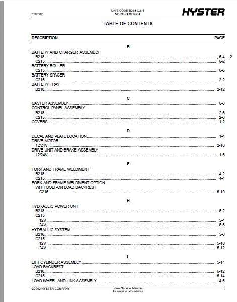
TABLE OF CONTENTS:
Hyster W40Z (B218) W45Z (C215) Parts Manual – PDF DOWNLOAD
Unlock-hyster-1499818-01-02-pm.....................................................................................................  1
1499818-B218-C215-H-PM-US-EN-(08-2013).............................................................................................109
	FRAME/DRIVE UNIT...............................................................................................................121
		COVERS.....................................................................................................................124
		DECAL AND PLATE LOCATION...................................................................................................126
		DRIVE UNIT AND BRAKE ASSEMBLY 12/24 VOLT...................................................................................128
		POWER HEAD ASSEMBLY........................................................................................................132
	ELECTRICAL SYSTEM..............................................................................................................135
		BATTERY SPACER C215........................................................................................................138
		BATTERY TRAY AND CHARGER ASSEMBLY B218  (→ 10/2002) .......................................................................140
		BATTERY TRAY AND CHARGER ASSEMBLY B218  (10/2002 ↔ S/N B218N26948L) .......................................................142
		BATTERY TRAY AND CHARGER ASSEMBLY B218  (S/N B218N26949L →) ...............................................................146
		BATTERY CHARGER ASSEMBLY (B218)............................................................................................150
		BATTERY CHARGER ASSEMBLY B218  (5/2005 ↔ 11/2007) .........................................................................152
		BATTERY CHARGER ASSEMBLY B218  (11/2007 → (120 Volt))  (3/2008 → (230 Volt)) ..............................................154
		BATTERY CONNECTOR AND CABLE ASSEMBLY.......................................................................................156
		CONTROL PANEL ASSEMBLY B218................................................................................................158
		CONTROL PANEL WIRING C215..................................................................................................160
		CONTROL PANEL ASSEMBLY C215................................................................................................162
		DRIVE MOTOR 12/24 VOLT.....................................................................................................164
		WIRE HARNESS MAIN - 24 VOLT ...............................................................................................165
		WIRE HARNESS MAIN - 12 VOLT ...............................................................................................167
	STEER HANDLE/BRAKE SYSTEM......................................................................................................169
		TILLER HANDLE ARM ASSEMBLY COMPOSITE TILLER HEAD...........................................................................172
		TILLER HEAD ASSEMBLY COMPOSITE  (→ 9/2005) ................................................................................176
		TILLER HEAD ASSEMBLY COMPOSITE  (9/2005 →) ................................................................................178
		TILLER HANDLE ARM ASSEMBLY METAL TILLER HEAD  (S/N B218N18568G →) .........................................................182
		TILLER HEAD ASSEMBLY METAL  (S/N B218N18568G →) ...........................................................................184
	LIFT LINKAGE AND FORKS.........................................................................................................187
		FORK AND FRAME WELDMENT 9 INCH BATTERY COMPARTMENT - B218   (11/2005 ↔ S/N B218N19717H) ...................................190
		FORK AND FRAME WELDMENT 9 INCH BATTERY COMPARTMENT - B218   (S/N B218N19718H →) ...........................................192
		FORK AND FRAME WELDMENT 8 INCH BATTERY COMPARTMENT - B218   (→ S/N B218N19718H) ...........................................194
		FORK AND FRAME WELDMENT 8 INCH BATTERY COMPARTMENT - B218   (S/N B218N19718H →) ...........................................195
		FORK AND FRAME WELDMENT WITHOUT LOAD BACKREST - C215 ......................................................................197
		LOAD WHEEL AND LINK ASSEMBLY...............................................................................................200
		LOAD WHEEL AND LINK ASSEMBLY...............................................................................................202
		LOWER LINK.................................................................................................................204
		UPPER LINK.................................................................................................................205
	HYDRAULIC SYSTEM...............................................................................................................207
		HYDRAULIC POWER UNIT B218..................................................................................................210
		HYDRAULIC POWER UNIT C215 - 12 VOLT .......................................................................................212
		HYDRAULIC POWER UNIT C215 - 24 VOLT .......................................................................................214
		HYDRAULIC SYSTEM B218......................................................................................................216
		HYDRAULIC SYSTEM C215 - 12 VOLT ...........................................................................................218
		HYDRAULIC SYSTEM C215 - 24 VOLT ...........................................................................................220
		LIFT CYLINDER ASSEMBLY.....................................................................................................222
	OPTIONS........................................................................................................................225
		FORK AND FRAME WELDMENT OPTION WITH BOLT-ON LOAD BACKREST - B218 WITH 9 INCH BATTERY COMPARTMENT   (→ S/N B218N19717H) ....228
		FORK AND FRAME WELDMENT OPTION WITH BOLT-ON LOAD BACKREST - B218 WITH 9 INCH BATTERY COMPARTMENT   (S/N B218N19718H →) ....230
		STABILIZERS FREIGHTERS SPECIAL.............................................................................................232
		BATTERY AND CHARGER ASSEMBLY C215..........................................................................................234
		BATTERY AND CHARGER ASSEMBLY B218..........................................................................................236
		BATTERY ROLLER C215........................................................................................................238
		CASTER ASSEMBLY............................................................................................................240
		FORK AND FRAME WELDMENT OPTION WITH BOLT-ON LOAD BACKREST - C215 ..........................................................242
		LOAD BACKREST B218.........................................................................................................244
		LOAD BACKREST C215.........................................................................................................246
		STABILIZER.................................................................................................................248
		STABILIZER.................................................................................................................249
		ZAPI HANDSET KIT...........................................................................................................250
		ZAPI LAPTOP/PC KIT WINDOWS.................................................................................................251
	FIELD CONVERSION KITS..........................................................................................................253
		HANDLE UPGRADE KIT.........................................................................................................256
	NUMERICAL INDEX................................................................................................................257
DESCRIPTION:
Hyster W40Z (B218) W45Z (C215) Parts Manual – PDF DOWNLOAD
HOW TO USE THE ILLUSTRATED PARTS MANUAL :
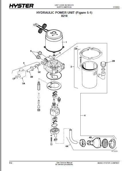
- This parts manual describes and illustrates assemblies, subassemblies, and detail parts needed for service replacement.
- The different constructions are indicated by keys and footnotes. The callouts correspond to descriptions found on the next page.
HOW TO FIND THE DESIRED PART NUMBER
WHEN THE PART NUMBER AND THE NEXT HIGHER ASSEMBLY IS NOT KNOWN:
1. Determine the function and application of the part required. Turn to the Sections Page. Choose the general area of reference most likely to include the part.
WHEN THE PART NUMBER AND THE NEXT HIGHER ASSEMBLY IS NOT KNOWN:
1. Determine the function and application of the part required. Turn to the Sections Page. Choose the general area of reference most likely to include the part.
2. Turn to the section you chose. Use the Section Table of Contents to determine the assembly which would normally contain the part required. Then locate the part on the assembly breakdown page.
WHEN THE PART NUMBER IS NOT KNOWN AND THE NEXT HIGHER ASSEMBLY IS KNOWN:
3. Determine the assembly the required part is used on. Turn to the Table of Contents (Page i).
WHEN THE PART NUMBER IS NOT KNOWN AND THE NEXT HIGHER ASSEMBLY IS KNOWN:
3. Determine the assembly the required part is used on. Turn to the Table of Contents (Page i).
4. Locate the assembly the required part is used on and turn to the page indicated for that assembly. Then locate the part on the assembly breakdown page.
WHEN THE PART NUMBER IS KNOWN:
5. Use the Numerical Index (Page 7-1) to find the part number. Turn to the page listed and locate the part as indicated by the item number.
GENERAL:
The assembly breakdowns include part numbers, descriptions, quantities required, keys and footnotes to help in selecting correct parts.
6. Parts Supersession Information. Part numbers that have this history will be displayed in the parts list in the order that they were superseded (from oldest to newest). The superseded part numbers will be shown with a line through them.
- Five periods in the PART NO. column (. . . . .) indicate that the part is either Not Serviced Separately or there is a reference to another figure. A figure reference is denoted by a pointing hand followed by a figure number in the DESCRIPTION column (FFigure 10)
7. Keys are used to show two or more similar assemblies, RH and LH assembly parts, etc. Select the appropriate key, “A”, “B”, “C”, “D”, or “E” and the corresponding quantity column to find the required parts. Two periods in the QTY column (..) indicate that the part is not used for that assembly.
HYSTER W40Z (B218) W45Z (C215) PARTS MANUAL – PDF DOWNLOAD:
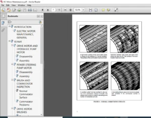
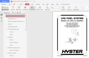
IMAGES PREVIEW OF THE MANUAL:
PLEASE NOTE:
- This is the SAME manual used by the dealers to troubleshoot any faults in your vehicle. This can be yours in 2 minutes after the payment is made.
- Contact us at [email protected] should you have any queries before your purchase or that you need any other service / repair / parts operators manual.
S.V