Trusted Business
Verified & Licensed
Virus Free Files
100% Safe Downloads
Secure Payment
SSL Protected
Instant Delivery
Available Immediately
Hyundai HT100V Skid Loader Service Manual – PDF DOWNLOAD
$32.95
Instant PDF Download
Available immediately
Save to Your Device
Download & keep forever
Antivirus Scanned
100% virus-free
Trusted Worldwide
175,000+ customers
Description
Hyundai HT100V Skid Loader Service Manual – PDF DOWNLOAD
The Hyundai HT100V Skid Loader Service Manual is a detailed PDF guide for maintenance and repairs. Downloadable for easy access, ensuring efficient servicing of the HT100V Skid Loader.
FILE DETAILS:
Hyundai HT100V Skid Loader Service Manual – PDF DOWNLOAD
Language : English
Pages : 739
Downloadable : Yes
File Type : PDF
IMAGES PREVIEW OF THE MANUAL:
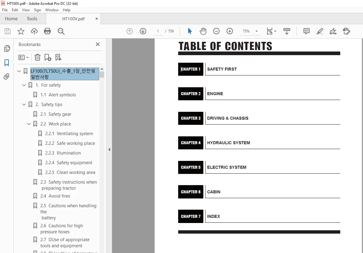
TABLE OF CONTENTS:
Hyundai HT100V Skid Loader Service Manual – PDF DOWNLOAD
LF100(TL750U)_수출_1장_안전및일반사항 0
1 For safety 3
1 1 Alert symbols 3
2 Safety tips 4
2 1 Safety gear 4
2 2 Work place 4
2 2 1 Ventilating system 4
2 2 2 Safe working place 4
2 2 3 Illumination 4
2 2 4 Safety equipment 4
2 2 5 Clean working area 4
2 3 Safety instructions when
preparing tractor 5
2 4 Avoid fires 5
2 5 Cautions when handling the
battery 6
2 6 Cautions for high pressure hoses 6
2 7 Use of appropriate tools andequipment 7
2 8 Handling of hazardous materials 7
2 9 Handling of rotating blade, shaft and driving belt 8
2 10 Prevention of scald 8
2 11 Disposal of environmental waste 9
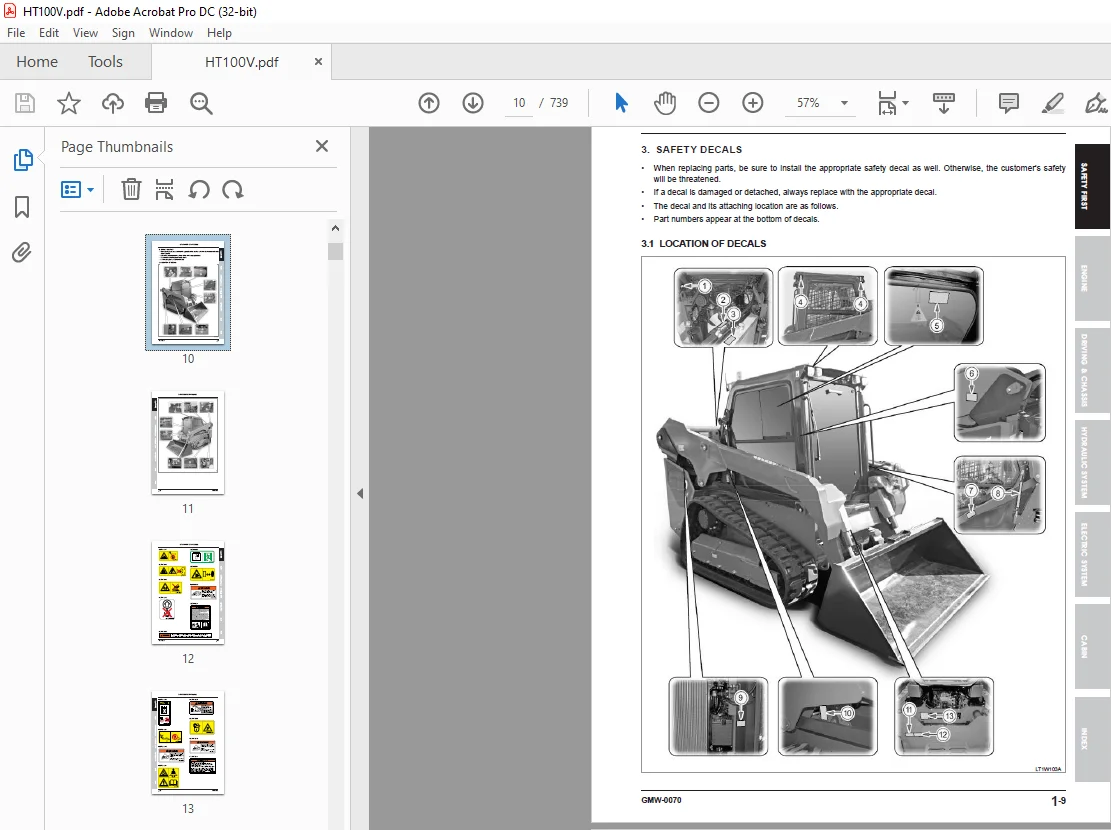
3 Safety decals 10
3 1 Location of decals 10
4 Description for symbols and abbreviations 16
5 Identification number 17
5 1 Skid loader serial number 17
5 2 Engine serial number 17
6 Exterior view & interior cabin 18
6 1 Exterior view 18
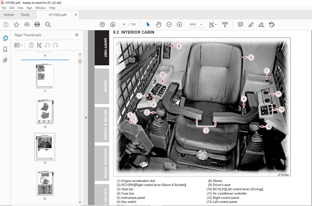
6 2 Interior cabin 19
6 3 Dimensions 20
7 Specifications 21
8 Maintenance 23
8 1 Maintenance schedule chart 23
8 2 Lubrication list 24
8 3 Daily check 25
8 3 1 Fuel system check 25
8 3 2 Coolant check 26
8 3 3 Engine oil check 28
8 3 4 Fluid oil check 29
8 3 5 Fan belt tension adjustment 31
8 3 6 Air cleaner check 32
8 3 7 Drive sprocket mounting bolt adjustment 33
8 3 8 Fuse replacement 33
8 3 9 Grease lubrication (Applying port) 34
9 General precautions 36
9 1 Assembly and disassembly 36
9 2 Tubes and rubbers 37
9 3 Lubricant 37
9 4 Handling precautions for electrical parts and wiring 37
10 Tightening torque 40
10 1 General use screws, bolts and nuts 40
10 2 Stud bolts 40
10 3 American standard screws, bolts and nuts with unc or unf threads 41
10 4 High pressure hose union nut 41
10 5 O-ring face type screw 41
10 6 Fitting fixing screw 41
11 Part number assignment standard for KIOTI bolts and nuts 42
11 1 Part number assignment standard for KIOTI bolts 42
11 2 Part number assignment standard for KIOTI nuts 43
12 Unit conversion table 44
LF100(TL750U)_수출_2장_엔진부 46
1 Engine identification 48
1 1 Engine EPA decal (A) 48
1 2 Engine number 48
1 3 Assignment standard for engine model code 49
2 Specifications 50
2 1 General specifications 50
2 2 Engine dimension 51
2 3 Components 52
2 4 Engine performance curve 53
2 5 Engine performance curve analysis 54
2 5 1 Torque 54
2 5 2 Brake horse power (HP) 54
2 5 3 S F C (Specific Fuel Consumption) (for reference only) 55
2 6 Servicing specifications 56
2 6 1 Engine body 56
2 6 2 Lubricating system 59
2 6 3 Cooling system 59
2 6 4 Tightening torques for engine 60
3 Operating principle 61
3 1 CRDI (Common Rail Direct Injection) system 61
3 1 1 ECU(Electronic Control Unit) 63
3 1 2 High pressure fuel pump (for injection) 72
3 1 3 Fuel rail(Common rail) 73
3 1 4 Injector [C3I] 73
3 2 Body and power train system 77
3 2 1 Cylinder head 77
3 2 2 Cylinder block 78
3 2 3 Cylinder honing 78
3 2 4 Crankshaft 78
3 2 5 Piston and piston ring 78
3 2 6 Connecting rod 79
3 2 7 Camshaft 79
3 2 8 Rocker arm assembly 79
3 2 9 Intake and exhaust valves 80
3 2 10 Timing gear 80
3 2 11 Flywheel 81
3 2 12 MLS cylinder head gasket 81
3 3 Lubricating system 82
3 3 1 Engine oil flow 82
3 3 2 Engine oil flow chart 83
3 3 3 Function of lubricating system 84
3 4 Cooling system 86
3 4 1 Coolant flow route 86
3 4 2 Water pump 87
3 4 3 Thermostat 87
3 4 4 Radiator 88
3 4 5 Radiator cap 88
3 4 6 Clutch fan 89
3 5 Fuel system 91
3 5 1 Overview for fuel supply 91
3 5 2 Fuel flow route 91
3 5 3 Fuel filter 93
3 5 4 Bleeding the fuel system 94
3 5 5 High pressure fuel pump 95
3 5 6 Common rail (Fuel rail) 97
3 5 7 Injector [C3I (Calibration Improved Individual Injector)] 98
3 5 8 Fuel heater and fuel cooler 99
3 6 Acceleration system 100
3 7 Intake & Exhaust system 102
3 7 1 Overview 102
3 7 2 EGR cooler 104
3 7 3 EGR valve 104
3 7 4 Air control vavle 106
3 7 5 CCRT (Catalyzed Continuously Regenerating Trap) 107
3 7 6 Turbo charger 112
3 8 Sensor 113
3 8 1 Sensors as input/output for ECU 116
4 Troubleshooting 117
5 Measurement and adjustment 120
5 1 Fan belt 120
5 2 Piston compression pressure measurement 120
5 3 Valve clearance 121
5 3 1 4 CYL 121
5 4 Valve lift (Deflection and worn condition of valve cam, tappet, push rod, rocker arm, etc ) 122
5 5 Oil pressure measurement 123
5 6 Bubble test for radiator 123
5 7 Turbo charger wastegate pressure check 124
6 Exploded view 125
6 1 EH5-G111001 Cylinder block group 125
6 2 EH5-G113003 Cylinder head group 126
6 3 EH5-G114002 Gear case group 127
6 4 EH5-G121001 Crank shaft group 128
6 5 EH5-G122001 Piston connecting rod group 129
6 6 EH5-G123001 Camshaft group 130
6 7 EH5-G124002 Idle gear group 131
6 8 EH5-G125001 Rocker arm valve group 132
6 9 EH5-G131001 Intake manifold group 133
6 10 EH5-G134001 Turbo group 134
6 11 EH5-G135001 Turbo pipe group 135
6 12 EH5-G141001 Oil pump group 136
6 13 EH5-G144001 Oil filter group 137
6 14 EH5-G151001 Fuel equipment group 138
6 15 EH5-G162001 Water flange group 139
6 16 EH5-G163003 Water pump group 140
6 17 EH5-G171001 EGR group 141
6 18 EH5-G172001 EGR cooler group 142
6 19 EH5-G191002 Glow plug group 143
6 20 EH5-G192001 Engine electrical group 144
6 21 EH5-G194001 ECU group 145
6 22 LF1-G012002 Cooling fan group 146
6 23 LF1-G014001 Aftertreatment group 147
7 Disassembly, service and assembly 148
7 1 Engine removal 148
7 2 Assembling the engine 163
7 3 Engine component removal 181
7 4 Engine disassembly 187
7 4 1 Head cover 187
7 4 2 Glow plug and injector 188
7 4 3 Rocker arm assembly 189
7 4 4 Cylinder head 191
7 4 5 Intake and exhaust valves 193
7 4 6 High pressure fuel pump 195
7 4 7 Gear case 196
7 4 8 Gears in gear case 197
7 4 9 Piston and connecting rod 206
7 4 10 Flywheel and crankshaft 211
7 4 11 Oil filter 220
7 4 12 Oil pump 221
7 4 13 Thermostat 223
7 4 14 Water pump 224
7 4 15 Fuel filter 226
7 4 16 Turbo charger 226
8 Diagnosis 230
8 1 Diagnostic program 230
8 2 DTC (Diagnostic Trouble Code) 256
8 2 1 Composition 256
8 2 2 Erorr code & action 258
8 2 3 Fault diagnosis code description 272
LF100(TL750U)_수출_3장_주행 및 샤시부 314
1 Driving system 315
1 1 Overview 315
1 2 Major specification 316
1 3 Exploded view 317
1 4 Principle of power transfer & Specifications of components 318
1 4 1 Power transfer system 318
1 4 2 Specifications 320
1 5 Check & Adjustment 322
1 5 1 Crawler tension adjustment 322
1 5 2 Quick attachment check 322
1 5 3 Rear door operation check 323
2 Brake (Parking brake) 324
3 Working system 325
3 1 Working system holder (Quick Coupler) 325
4 Troubleshooting 327
4 1 Driving hydraulic system/brake 327
4 2 Control system 333
5 Exploded view 334
5 1 LF1-G121003 Clutch housing group 334
5 2 LF1-G4D2001 Lever guide group 335
5 3 LF1-G4H1001 Undercarriage group 336
5 4 LF1-G4H2001 Track group 337
5 5 LF1-G421003 Cooling system group 338
5 6 LF1-G431003 Fuel tank group 339
5 7 LF1-G432001 Fuel cooler group 340
5 8 LF1-G461002 Main frame group 341
5 9 LF1-G462002 Boom frame group 342
5 10 LF1-G463001 Rotation frame group 343
5 11 LF1-G464001 Control frame group 344
5 12 LF1-G465002 Quick attach group 345
5 13 LF1-G472001 Rear door group 346
6 Maintenance 347
6 1 Undercarriage disassembly, assembly 347
6 2 Boom disassembly 352
6 3 Fuel tank disassembly 353
6 4 Fuel cooler disassembly 355
6 5 Intercooler disassembly 356
LF100(TL750U)_수출_4장_유압부 358
1 Specifications 360
2 Hydraulic system overview 362
2 1 Hydraulic system layout 362
2 2 Circuit diagram for hydraulic system 366
2 3 Connecting lines by hydraulic system groups 368
2 3 1 HST group 368
2 3 2 Oil tank group 375
2 3 3 Suction line group 375
2 3 4 Hydraulic pump group 376
2 3 5 Oil cooler group 377
2 3 6 Tilt cylinder group 378
2 3 7 Lift cylinder group 379
2 3 8 High flow group 380
2 3 9 Quick attachment cylinder group 381
2 3 10 External hydraulic group 382
2 4 Connecting lines for hydraulic valves 383
2 4 1 Pilot lock valve (LF13-0284) 383
2 4 2 Shift valve (LF13-0286) 384
2 4 3 Parking valve (LF13-0090) 385
2 4 4 Self level valve (LF13-0218) 386
2 4 5 Quick attachment valve (LF13-0307) 387
2 4 6 Main control valve (LF13-0028) 388
2 4 7 RCV assembly (RH) (LF13-0056) 389
2 4 8 RCV assembly (LH) (LF13-0055) 390
2 5 Hose connecting lines for a driving system and circulation system 391
2 5 1 Hydraulic hose (LF13-0022A) 391
2 5 2 Hydraulic hose (LF13-0158A) 392
2 5 3 Hydraulic hose (LF13-0160A) 393
2 5 4 Hydraulic hose (LF13-0323A) 394
2 5 5 Hydraulic hose (LF13-0325A) 395
2 5 6 Hydraulic hose (LF13-0340A) 396
2 5 7 Hydraulic hose (LF13-0341A) 397
2 5 8 Hydraulic hose (LF13-0402A) 398
2 5 9 Hydraulic hose (LF13-0403A) 399
2 5 10 Hydraulic hose (LF13-0404A) 400
2 5 11 Hydraulic hose (LF13-0407A) 401
2 5 12 Hydraulic hose (LF13-0408A) 402
2 5 13 Hydraulic hose (LF13-0412A) 403
2 5 14 Hydraulic hose (LF13-0414A) 404
2 5 15 Hydraulic hose (LF13-0439A) 405
2 5 16 Hydraulic hose (LF13-0576A) 406
3 Main components 407
3 1 HST pump (Driving pump) 407
3 2 Gear pump (Main+Charge+High flow pump) 409
3 3 Track(HST) motor 412
3 4 Main control valve (MCV) 414
3 5 Pilot lock valve 416
3 6 Self level valve 417
3 7 High flow valve 419
3 8 Shift valve 421
3 9 Parking valve 422
3 10 Ride control valve [option] 423
3 11 Quick attachment valve 424
3 12 RCV assembly (LH) 425
3 13 RCV assembly (RH) 427
3 14 Hydraulic cylinder 429
3 14 1 Lift cylinder 429
3 14 2 Tilt cylinder 430
3 14 3 Quick attachment cylinder 431
3 15 Hydraulic filter 432
3 15 1 Return filter 432
3 15 2 HST filter 434
3 15 3 Oil strainer 436
3 16 Quick coupler (External hydraulic) 438
3 17 Oil cooler 440
4 Operating principle 441
4 1 Track(HST) motor 442
4 2 Self level valve 444
4 3 RCV (R/H) 448
4 3 1 Boom operation (Up) 449
4 3 2 Boom operation (Down) 450
4 3 3 Self leveling 451
4 3 4 Ride control [Option] 452
4 3 5 Bucket operation (Roll back) 453
4 3 6 Bucket operation (Dump) 454
4 3 7 Quick attachment 455
4 3 8 External implement 456
5 Check & Adjustment 459
5 1 Main control valve (MCV) system pressure 459
5 2 Main pump flow rate 460
5 3 Charging pump pressure 461
5 4 HST (Driving) pump pressure 462
5 5 HST (Driving) pump flow rate 463
5 6 relief pressure setting 464
6 Troubleshooting 465
7 Exploded view 466
7 1 LF1-G211003 Oil tank sub group 466
7 2 LF1-G214003 Oil cooler group 467
7 3 LF1-G221002 Main control valve group 468
7 4 LF1-G221503 Joystick group 469
7 5 LF1-G222003 Auxiliary hydraulic group 470
7 6 LF1-G223002 Lift cylinder group 471
7 7 LF1-G223504 Self leveling group 472
7 8 LF1-G224502 Tilt cylinder group 473
7 9 LF1-G225003 Quick attach cylinder group 474
7 10 LF1-G226002 Drain vavle group 475
7 11 LF1-G231003 HST group 476
8 Hydraulic system maintenance 477
8 1 Main pump detach 477
8 2 HST pump detach 478
8 3 Main pump, charge pump, high flow pump disassembly 481
8 4 Track(HST) motor disassembly 486
8 5 Main control valve detach & Disassembly 489
8 6 Self level valve detach & Disassembly 499
8 7 Pilot lock valve detach & Disassembly 504
8 8 shift valve detach & Disassembly 507
8 9 Parking valve detach & Disassembly 510
8 10 High flow valve detach & Disassembly 513
8 11 Ride control valve detach & Disassembly [OPTION] 517
8 12 Quick attachment valve detach & Disassembly 520
8 13 HST filter replacement 523
8 14 Return filter replacement 525
8 15 Lift cylinder disassembly 526
8 16 TILT cylinder disassembly 529
8 17 Quick attachment cylinder disassembly 531
8 18 RCV assembly & Oil tank disassembly 532
LF100(TL750U)_수출_5장_전장부 536
1 Specifications 537
2 Circuit and component location 538
2 1 Electric circuit diagram 538
2 2 Location of electronic components 540
3 Wiring identification 542
3 1 Wiring color identification 542
3 2 Cross sectional area of wiring 543
3 3 Symbols for electric components 543
3 4 Fuse 544
3 4 1 Inspection 544
3 4 2 Cause for blown fuse 544
3 5 Electric device diagnosis 545
4 Electric components 546
4 1 Engine room 546
4 1 1 Battery 546
4 1 2 Fuse box 546
4 1 3 Starter motor 548
4 1 4 Alternator 549
4 1 5 Glow plug 551
4 1 6 Coolant temperature sensor 551
4 1 7 Engine oil pressure switch 552
4 1 8 ECU 553
4 1 9 Sensors and relays 554
4 2 Cabin & Chassis 575
4 2 1 Ignition switch 575
4 2 2 Escort unit 576
4 2 3 Flasher 577
4 2 4 Switch panel 577
4 2 5 Engine accelerator dial 579
4 2 6 Accelerator pedal sensor 580
4 2 7 Relay box 582
4 2 8 Instrument panel 583
4 2 9 MCU (Micro Controller Unit) 610
4 2 10 Telemetics controller 624
4 2 11 RCV assembly (LH) (RH) 626
4 2 12 SAFETY SENSOR (SAFETY BAR) 627
4 2 13 Seat switch 628
4 2 14 Oil temperature sensor 629
4 2 15 Horn 629
4 2 16 Wiper motor 630
4 3 Lamps (Bulb replacement) 631
4 3 1 Led work lamp 631
4 3 2 Turn signal lamp 631
4 3 3 Brake lamp (Rear lamp) /
Turn signal lamp 632
4 3 4 Room lamp 633
5 Troubleshooting 634
5 1 When the engine cannot be started 634
5 2 When the system is not charged 636
5 3 When the system is not preheated automatically 638
5 4 When work lamp cannot be operated 641
5 5 Fuel gauge operation 643
5 6 Temperature gauge operation 644
5 7 Hour meter operation 645
6 Wiring diagram 646
6 1 Main 646
6 2 Cabin 648
6 3 MCU update 650
7 Exploded view 651
7 1 LF1-G311007 Engine electrical group 651
7 2 LF1-G327001 Light control group 652
7 3 LF1-G328002 Power socket group 653
7 4 LF1-G331001 Wire harness group 654
7 5 LF1-G332002 Cluster control group 655
7 6 LF1-G332501 Fuel sender group 656
7 7 LF1-G333501 Vehicle control group 657
LF100(TL750U)_수출_6장_캐빈부 658
1 Cabin 659
1 1 Interior devices 659
1 2 Exterior devices 659
1 3 Cabin components 660
1 3 1 Air conditioner controller 660
1 3 2 Wiper notor 662
1 3 3 Washer tank 663
1 3 4 Wiper/Washer fluid switch 663
1 3 5 Stereo (Bluetooth) 663
1 3 6 Antenna 663
1 3 7 Speaker 663
2 Heating & Cooling system 664
2 1 Specifications 664
2 2 HVAC system flow diagram 664
2 3 Components 665
2 3 1 Compressor 665
2 3 2 Receiver-drier 666
2 3 3 Condenser 667
2 3 4 Air conditioner 668
2 3 5 Air inlet/vent 675
2 3 6 Electric fan motor 675
3 Operating principle 677
3 1 Cooling operation 677
3 1 1 Cooling cycle 678
3 1 2 Refrigerant and refrigeration oil 679
4 Inspection and adjustment 680
4 1 Inspection with gauge 680
4 2 Normal condition 680
4 3 Insufficient refrigerant 680
4 4 Excessive refrigerant and insufficient condenser cooling performance 681
4 5 Air intrusion into cycle 681
4 6 Defective expansion valve 682
4 7 Poor compressor compression 682
4 8 Moisture intrusion into cooling cycle 683
4 9 Poor recirculation of refrigerant 683
4 10 Cabin system inspection 684
4 10 1 Leakage test 684
4 10 2 When assembling 684
5 Troubleshooting 688
5 1 Visual and auditory inspection 688
5 2 Troubleshooting by symptoms 689
5 3 Troubleshooting poor cooling/heating performance 690
5 3 1 Poor cooling performance 690
5 3 2 Poor heating 692
6 Exploded view 693
6 1 LF1-G334001 Speaker antenna group 693
6 2 LF1-G335501 Wiper motor group 694
6 3 LF1-G4A1006 Door group 695
6 4 LF1-G4E1001 Wiper group 696
6 5 LF1-G451001 Air conditioner drive group 697
6 6 LF1-G466001 Cabin support group 698
6 7 LF1-G491001 Cabin frame group 699
6 8 LF1-G4B1001 Air conditioner group 700
6 9 LF1-G4B2001 Air conditioner duct group 701
7 Maintenance 702
7 1 Opening the cabin (Lifting up) 702
7 2 Cabin removal 703
7 3 Cabin components disassembly & Assembly 707
7 4 Air conditioner & Heater disassembly 719
7 5 Condenser disassembly 725
7 6 Fan motor disassembly 727
7 7 Compressor disassembly 727
7 8 Compressor assembly 729
7 9 Heat hose/air conditioner hose assembly 730
7 9 1 Heater hose 730
7 9 2 A/C hose (Refrigerant) 730
LF100(TL750U)_수출_7장_색인 732
Questions? Email us: [email protected]
https://vimeo.com/915906136?share=copy
S.V 02/24