Hyundai HX220LL Excavator Service Manual – PDF DOWNLOAD
$36.95
Description
Hyundai HX220LL Excavator Service Manual – PDF DOWNLOAD
FILE DETAILS:
Hyundai HX220LL Excavator Service Manual – PDF DOWNLOAD
Language : English
Pages :1161
Downloadable : Yes
File Type : PDF
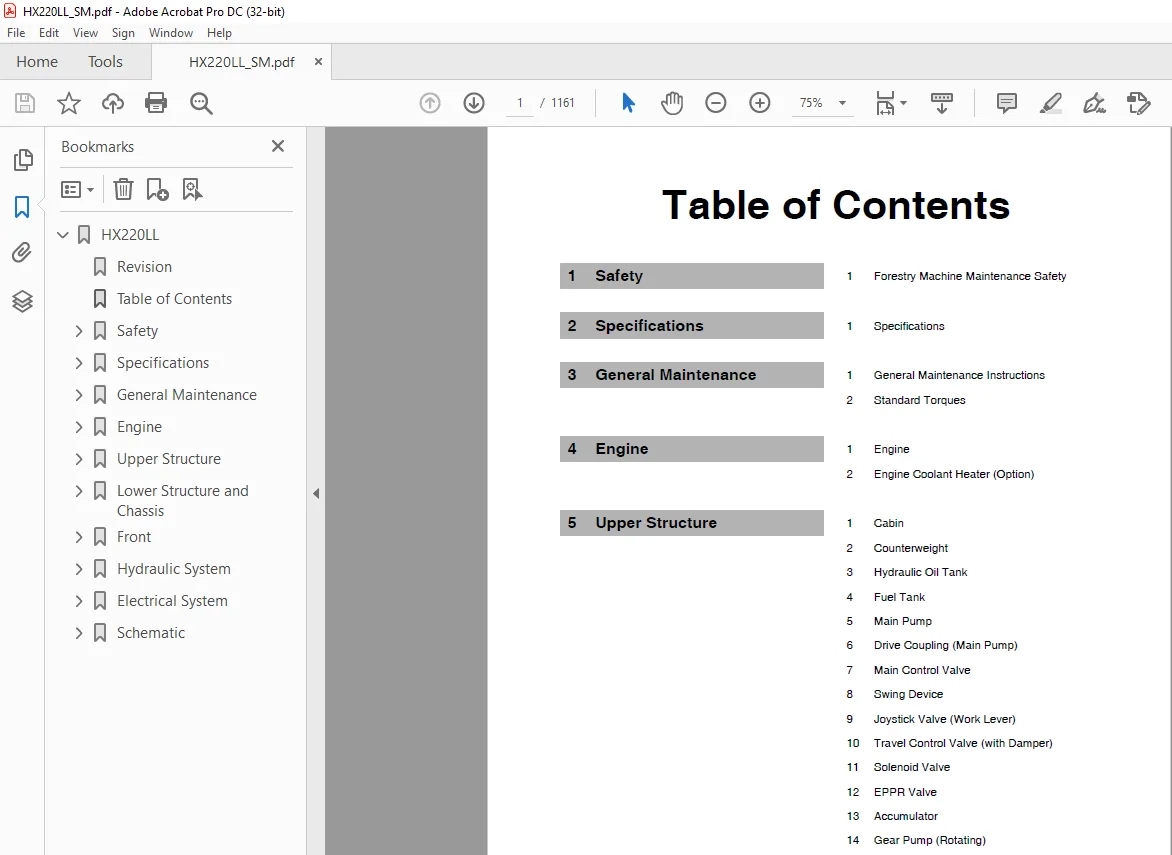
TABLE OF CONTENTS:
Hyundai HX220LL Excavator Service Manual – PDF DOWNLOAD
HX220LL 0
Revision 0
Table of Contents 1
Safety 3
Forestry Machine Maintenance Safety 5
Safety Instructions 5
General 7
Safe Operation is Operator’s Responsibility 7
Know Your Machine 7
Proper Work Tools and Attachments 8
Pressurized Fluids 8
Flying or Falling Objects 9
Personal Protective Equipment (PPE) 10
Correction of Machine Problems 10
Crushing and Cutting 10
Hot Coolant and Oils Burn Prevention 11
Fire and Explosion Prevention 12
Fire Extinguisher and Firstaid Kit (Emergency Medical Kit) 15
Electrical System and Electrical Shock 16
Operator Protective Guards and Structures (Optional) 16
Emergency Exit from Operator’s Station 17
Transportation 18
Obey State and Local OvertheRoad Regulations 18
Loading and Unloading 18
Transporting Machine 19
Operation 20
Before Engine Starting 20
Work Site 21
Mounting/Dismounting 22
Cleaning 23
Operator Station 23
Seat Belt 24
Visibility Information 25
Boost Starting or Charging Engine Batteries 26
Starting Engine 27
Swinging or Traveling 28
Lifting and Logging 30
Operation on Slopes 31
Towing 32
Attachment 33
Equipment Lowering with Engine Stopped 33
Engine Stop 34
Parking Machine 34
Preservation/Storing Machine 35
Maintenance 37
Warning Tag 39
Cleaning 40
Proper Tools and Clothing 40
Disassembling Precautions 40
Use of Lighting 40
Fire and Explosion Prevention 41
Burn Prevention 42
Rubber That Contains Fluorides 43
Rubber and Plastics 44
Welding Repairs 45
Warning for Counterweight and Front Attachment Removal 46
Lock Inspection Covers 47
Working on Machine 47
Accumulator 48
Compressed Air 48
Track Tension Adjustments 49
Supports and Blocking for Work Equipment 49
Highpressure Lines, Tubes and Hoses 50
Battery 51
Environment and Circumstances 53
Work Site Areas Requiring Extra Caution 53
Highvoltage Cables 54
Working in Water 55
Working in Contaminated Environment 55
Operation in Extreme Conditions 55
Exhaust Ventilation 60
Asbestos Information 60
Silica Dust Information 61
Disposal of Hazardous Materials 61
Specifications 63
Specifications 65
Safety Instructions 65
General Description 67
Component Locations 68
Overall Dimensions 72
Working Range 74
General Specifications 75
Approximate Weight of Workload Materials 76
Performance Tests 78
Purpose of Performance Tests 78
Kinds of Tests 78
Performance Standards 78
Precautions for Evaluation of Test Data 78
Definition of “Performance Standard” 78
Preparation for Performance Tests 79
The Machine 79
Test Area 79
Precautions 79
Make Precise Measurement 79
Operational Performance Standard Table 80
Operational Performance Test 84
Hydraulic Cylinder Cycle Time 84
Travel Speed 86
Track Revolution Speed 87
Mistrack Check 89
Swing Speed 91
Swing Function Drift Check 92
Cylinder Creep 94
General Maintenance 97
General Maintenance Instructions 99
Safety Instructions 99
Welding Precautions and Instructions 101
Hydraulic System General Precautions 102
Maintenance Service and Repair Procedure 104
General Precautions 104
Hydraulic System Cleanliness and Oil Leaks 105
Maintenance Precautions for Hydraulic System Service 105
Oil Leakage Precautions 106
Cleaning and Inspection 107
General Instructions 107
Bearing Inspection 108
Standard Torques 115
Safety Instructions 115
Torque Values for Standard Metric Fasteners 117
Torque Values for Standard US Fasteners 118
Type 8 Phosphate Coated Hardware 120
Torque Values for Hose Clamps 121
ORFS Swivel Nut Recommended Torque 121
Torque Values for Split Flanges 122
Torque Wrench Extension Tools 123
Torque Multiplication 123
Other Uses for Torque Wrench Extension Tools 124
Tightening Torque Specifications (Metric) 125
Engine 129
Engine 131
Safety Instructions 131
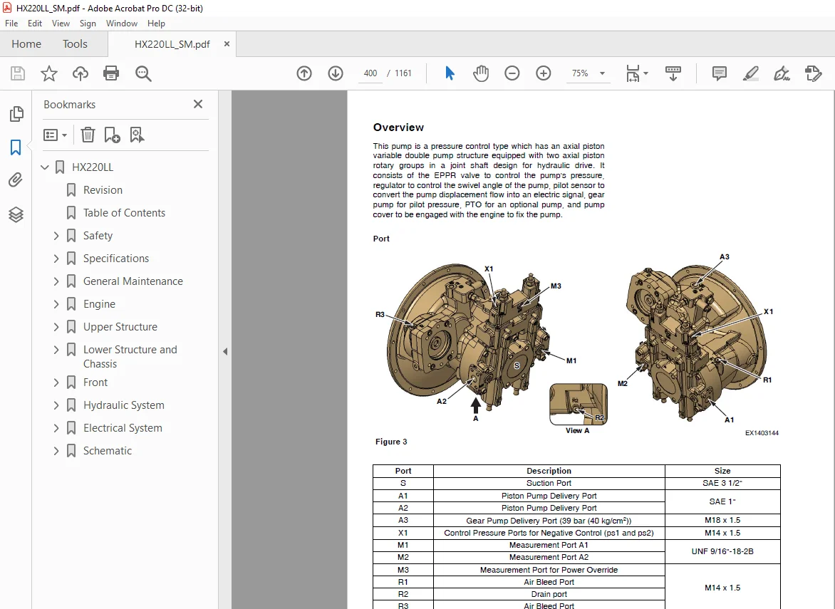
Overview 134
General Information 135
General Description 135
Engine Maintenance 139
Inspection and Repair of the Engine 142
Engine Identification 144
Engine Data Plate 144
Engine Specification 146
Engine Performance Curves 147
Special Tools 148
Tightening Torques 152
Major Parts Tightening Torque 152
Tightening Torque for General Bolts 154
Tightening Torque of Plug Screw 155
Hollow Screw (4Hole) Tightening Torque 155
Engine Disassembly 156
Engine Disassembly 156
Engine Assembly 172
Engine Assembly 172
Cylinder 195
General Information 195
Cylinder Head 195
Cylinder Block 200
Valve Mechanism 202
Actuating System 214
Camshaft 214
Piston 216
Connecting Rod 220
Crankshaft 222
Timing Gear 227
Lubrication system 228
General Information 228
Oil Pan 232
Oil Pump 234
Oil Filter 236
Exhaust System 239
Turbocharger 239
EGR (Exhaust Gas Recirculation) System 251
DNOx System 258
Cooling System 269
General information 269
Thermostat 270
Cooling fan 273
Fuel System 275
General Information 275
Fuel Highpressure System Components 276
Injector 277
Common Rail 281
Fuel Injection Pump 286
Electrical System 289
Electrical Parts 289
Switches and Sensors 290
ECU (Electronic Control Unit) 294
Starter 296
Exhaust Gas Reduction 298
Circuit Diagram 302
Engine Coolant Heater (Option) 309
Safety Instructions 309
Disassembly and Assembly 311
Changing the Circulating Pump 311
Changing the Temperature Limiter 313
Changing the Temperature Sensor 314
Changing the Combustion Air Fan 316
Changing the Burner, Flame Monitor and Glow Plug 318
Changing the Burner Head 320
Changing the Heat Exchanger 322
Upper Structure 323
Cabin 325
Safety Instructions 325
Cabin Identification 327
Falling Object Guards and Structures 327
Removal 328
Installation 333
Completing work 333
Dimensions of Cabin Glass 334
Removal and Installation of Cabin Glass 338
Removal of Cabin Glass 338
Installation of Cabin Glass 340
Installation of Upper Door Glass 345
Installation of Upper Front Glass 345
Counterweight 347
Safety Instructions 347
General 349
Warning for Counterweight and Front Attachment Removal 349
Removal 351
Installation 352
Hydraulic Oil Tank 353
Safety Instructions 353
General 355
Specification 355
Parts List 356
Air Breather 358
Removal 359
Installation 366
Completing Work 367
Fuel Tank 369
Safety Instructions 369
General 371
Specification 371
Removal (Fuel Tank 1) 376
Installation (Fuel Tank 1) 383
Completing Work (Fuel Tank 1) 384
Removal (Fuel Tank 2) 385
Installation (Fuel Tank 2) 390
Completing Work (Fuel Tank 2) 391
Main Pump 393
Safety Instructions 393
General 397
Specifications 397
Overview 400
Hydraulic Circuit 401
Parts List 402
Theory of Operation 406
Section View 419
Removal 420
Installation 430
Completing Work 430
Assembly Guidelines for Tightening Torques 431
Bolts 431
Plugs with Internal Hexagon and Profile Seal Ring 432
Seallock Sealing Nuts 432
Disassembly and Reassembly 433
General Repair Guidelines 433
Seal Kits and Subassemblies 435
Sealing the Driveshaft 439
Gear Pump Sealing 441
Removing Control Housing 442
Control Module 445
Removing the Controller 447
Valve Plate with Valves 449
Remove Rotary Groups 450
Remove Intermediate Wheel 453
Remove Auxiliary Drive 455
Inspection 458
Assembling the Rotary Group 463
Pump Assembly 465
Hydraulic Component Measurement “D” 468
Installation of Control Housing 471
Assembly of Intermediate Wheel 474
Installation of Gear Pump 475
Installation of Cover/Auxiliary Drive 476
Troubleshooting 477
How to Proceed for Troubleshooting 477
Malfunction Table 478
Drive Coupling (Main Pump) 481
Safety Instructions 481
General 483
Description 483
Specification 483
Parts List 484
Section View 486
Tools 487
Disassembly 488
Reassembly 489
Main Control Valve 491
Safety Instructions 491
General 493
Specification 493
Overview 494
Parts List 500
Theory of Operation 506
Cautions for Operation 534
Precaution 535
Tools and Torques 535
Removal 536
Installation 550
Completing Work 550
Disassembly 551
Caution on Disassembly 551
Sequence of Disassembly 552
Cleaning and Inspection 563
Cleaning 563
Inspection 563
Reassembly 564
Caution on Assembly 564
Sequence of Subassembly 565
Maintenance of Relief Valves 576
Troubleshooting, Testing and Adjustment 579
Troubleshooting 579
Adjustment of Valves 581
Swing Device 585
Safety Instructions 585
General 587
Specification 587
Overview 588
Parts List 590
Theory of Operation 595
Cautions for Operation 603
Removal 606
Installation 611
Completing work 612
Precaution 613
Tools for Disassembly and Assembly 613
Tightening Torque 613
Disassembly 615
Swing Motor 615
Swing Reduction Gear 620
Reassembly 624
Swing Motor 624
Swing Reduction Gear 630
Troubleshooting 638
General Instructions 638
Examination of Hydraulic Motor 638
Troubleshooting 639
Maintenance Instructions 642
Replacement Standard of Worn Parts 642
Standard of Sliding Surface Correction 642
Joystick Valve (Work Lever) 643
Safety Instructions 643
General 645
Specifications 645
Overview 646
Parts List 648
Theory of Operation 650
Tools and Torques 651
Section View 652
Removal 654
Installation 659
Completing work 660
Disassembly 661
Reassembly 665
Travel Control Valve (with Damper) 671
Safety Instructions 671
General 673
Specification 673
Overview 674
Parts List 676
Theory of Operation 678
Tools and Torques 679
Section View 680
Removal 681
Installation 686
Completing Work 687
Disassembly 688
Reassembly 691
Troubleshooting 696
Solenoid Valve 697
Safety Instructions 697
General 699
Specification 699
Overview 700
Parts List 702
Theory of Operation 703
Disassembly and Reassembly 704
Troubleshooting 705
EPPR Valve 707
Safety Instructions 707
General 709
Specification 709
Overview 710
Hydraulic Circuit 711
Troubleshooting 711
Accumulator 713
Safety Instructions 713
General 716
Specifications 717
Gear Pump (Rotating) 719
Safety Instructions 719
General 721
Specification 721
Overview 721
Location 722
Parts List 723
One Spool Valve (Rotating) 725
Safety Instructions 725
General 727
Specification 727
Overview 727
Theory of Operation 728
Disassembly and Assembly 730
General Cautions 730
Replacement of Spool 731
Replacement of Main Relief Valve 733
Replacement of Overload Relief Valve 734
Replacement of SubBlock 736
Rotating Grapple 739
Safety Instructions 739
General 741
General Description 741
Theory of Operation 741
Structure 742
Hydraulic Circuit 743
Lower Structure and Chassis 745
Swing Bearing 747
Safety Instructions 747
General 749
General Description 749
Parts List 749
Maintenance Guidelines 750
Disassembly 751
Reassembly 753
Center Joint 755
Safety Instructions 755
General 757
General Description 757
Overview 757
Parts List 758
Section View 759
Removal 760
Installation 766
Completing Work 766
Disassembly 767
Reassembly 770
Troubleshooting, Testing and Adjustment 772
Inspection 772
Testing 772
Travel Device 773
Safety Instructions 773
General 775
Specification 775
Overview 776
Parts List 778
Theory of Operation 782
Cautions for Operation 790
Precaution 794
Tools for Disassembly and Assembly 794
Tightening Torque 796
Removal 797
Installation 803
Completing Work 803
Checkup After Assembly 804
Performance Test 804
Section View 806
Disassembly 810
General Caution Matters 810
Reduction Gear 810
Hydraulic Motor 816
Cleaning and Inspection 821
Maintenance Standard 821
Reassembly 823
General Caution Matters 823
Hydraulic Motor 823
Reduction Gear 831
Troubleshooting 839
Track Assembly 843
Safety Instructions 843
General 845
Track Tension 846
Track Shoes and Links 848
Parts List 848
Track Removal 849
Track Installation 851
Track Shoe 852
Sprocket 854
Wear Limits and Tolerances 854
Front Idler 855
Parts List 855
Front Idler Disassembly 856
Front Idler Reassembly 858
Upper/Lower Roller 859
Overview 859
Parts List 860
Upper/Lower Roller Removal 861
Upper/Lower Roller Installation 861
Upper/Lower Roller Disassembly 862
Upper/Lower Roller Reassembly 863
Wear Limits and Tolerances 864
Track Adjuster 866
Parts List 866
Disassembly 867
Assembly 868
Front 871
Boom and Stick 873
Safety Instructions 873
Specifications 875
Size and Weight 876
Removal 877
Stick Removal 877
Boom Removal 879
Installation 880
Stick Installation 880
Boom Installation 880
Startup Procedures 880
Cylinders 883
Safety Instructions 883
General 885
General Description 885
Parts List 886
Theory of Operation 894
Seal of Cylinder 895
Special Tools and Materials 897
Piston Nut 897
Piston Jig 898
Steel Bushing Jig 899
Dust Wiper Jig 900
Slipper Seal Jig 901
Slipper Seal Straightening Jig 902
Rod Bushing (DDbushing) Pushingin Jig 903
Disassembly 904
Reassembly 909
Troubleshooting 913
Hydraulic System 915
Hydraulic System 917
Safety Instructions 917
General 919
General Description 919
Hydraulic Schematic 920
General Description 920
Hydraulic Component and Oil Flow 922
Hydraulic Components 922
Safety Cutoff Valve Operation 924
Power Up Valve Operation 926
Travel Highspeed Valve Operation 928
Operation of highspeed 929
Swing Brake Release Operation 930
Two Pump Operation 932
Travel Forward and Backward Operation 933
Boom Up Operation 934
Boom Down Operation 936
Arm (Stick) In Operation 938
Arm (Stick) Out Operation 940
Heel Rack In Operation 942
Heel Rack Out Operation 944
Hydraulic System Testing and Adjustment 947
Safety Instructions 947
Procedural Troubleshooting Baseline Recommendations 949
Initial Checks and Tests to Establish Operating Condition of the Excavator 949
Pilot Pressure 951
Adjustment and Testing 951
Power Mode Valve 952
Current Signal and Hydraulic Pressure Adjustments 952
Pressure Up Valve 953
Checks and Adjustments 953
Pump Input Power Control 955
Pump Regulator Adjustment 955
Flow Meter and Flow Meter Kit Installation and Testing 958
Swing System Troubleshooting 960
Precautions/Initial Checks 960
Swing Relief Valve Checking and Adjustment 961
Hydraulic System Troubleshooting 963
Safety Instructions 963
Hydraulic System 965
Unusual Noise Comes Out from Pump Connection 965
Engine Starts but Machine Does Not Operate 966
Hydraulic Oil is Cloudy 967
Hydraulic Oil Overheated 967
Hydraulic Pump Cavitation 968
Hydraulic Oil is Contaminated 968
Boom, Arm, Heel Speed is Slow 969
Boom, Arm or Heel Power is Weak 970
Cylinder Moves When Remote Control Valve is in the Neutral Position 970
TR (L), TR (R) Swing Does Not Operate When Remote Control Valve Operated 971
Swing Speed is Slow 972
Machine Swings but Does Not Stop 973
One Side Speed is Falls and the Machine Curves 974
Machine Does Not Stop on a Slope 975
Travel Motor is Powerless (Travel Only) 975
Machine Makes a Curved Travel, When Travel and Actuator Operation are Executed a the Same Time 976
Does Not Travel is 2nd Speed or Auto Speed 976
Troubleshooting – Swing Gearbox 977
Troubleshooting – Hydraulic Problems 978
Troubleshooting – Control Valve 980
Troubleshooting – Travel Control Valve 981
Troubleshooting – Joystick Control Valve 982
Electrical System 983
Electrical System 985
Safety Instructions 985
Introduction 989
Electrical Supply System 990
Engine Starting Circuit 992
Start Operation 992
After Start 994
Engine Stop 996
Charging System 998
Monitoring System 999
Instrument Panel1000
Functional Check1000
Monitoring System Schematic1002
Operation1004
Instruments1004
Warning and Indicator Lights1006
Indication of Warning Lights1006
Indication of Multifunction Gauge1009
Initial Operation1010
Graphic Information Area Display1012
Overview1012
Main Menus for the Graphic Display Area1012
Menu Selector Buttons1012
User Menu1013
User Menu Access and Escape Methods1013
Special Menu1044
Entering/Accessing and Exiting/Escaping Menus1044
Special Menu Selections1045
Failure Code1062
Failure Code at Machine1062
Failure Code at Engine Side1065
Electronic Hydraulic Control System (EPOS)1086
Control System Schematic1086
Power Plus Mode Control1088
Operation1090
Power Mode Control1092
Smart Power Control (SPC)1094
Operation1094
Engine Control System1097
Engine Control Dial1098
Engine Control1100
Automatic Deceleration Control (Auto Idle Control)1102
Engine Overheat Protection System1104
Power Boost Mode1107
Operation1107
Power Boost Control1108
Automatic Travel Speed Control1110
Automatic Travel Speed Control1112
Water in Fuel Warning System1113
Operation1113
Selfdiagnostic Function1114
EPOS Controller1114
Air Conditioner System1116
Outline1116
Internal and External Filters1117
AirConditioning System Layout1118
Air Conditioner/Heater Circuit Diagram1120
Air Conditioner/Heater Unit1122
Ambient Air Temperature Sensor1127
Sun Sensor1127
Control Panel1128
Receiver Dryer1135
Troubleshooting1136
Refrigerant System Repairs1138
Refrigerant Safe Handling Procedures1138
Repair and Replacement Procedure1139
Refrigerant Recovery1141
Vacuuming Refrigerant System1141
Leakage Check1143
Refrigerant Charging1143
Inspecting System For Leakage1145
Wiper System1146
Wiper Circuit1146
Wiper Operation1147
Lighting System1150
Lighting System Circuit Diagram1150
Kind of Light1151
Operation1151
Audio Controller1152
Audio Controller Circuit Diagram1152
Schematic1153
Hydraulic Schematic / Electrical Schematic1155
Hydraulic Schematic (1/2)1157
Hydraulic Schematic (2/2)1158
DX225LL5 (Log Loader)Electrical Schematic1159
DX225LL5 (Road Builder)Electrical Schematic1160
DX225LL5 (Oregon Cabin)Electrical Schematic1161
IMAGES PREVIEW OF THE MANUAL:
Need help? Contact: [email protected]
S.M 09/24