Icom IC-756 HF/50MHz Transceiver Service Manual PDF
Original price was: $95.00.$18.95Current price is: $18.95.
Factory service manual for the Icom IC-756 HF/50MHz all-band transceiver. Includes full specifications, receiver and transmitter circuits, PLL and IF stages, DSP board functions, antenna tuner circuits, power supply circuits, alignment and adjustment procedures, semiconductor data, board layouts, voltage diagrams, and parts information. Essential reference for radio repair technicians and amateur radio engineers
Description
Icom IC-756 HF/50MHz Transceiver Service Manual PDF DOWNLOAD
Description
The Icom IC-756 Service Manual provides complete technical documentation for servicing, repairing, aligning, and maintaining the IC-756 HF/50MHz all-band amateur radio transceiver.
The manual includes detailed RF architecture, IF signal paths, PLL and LO circuit theory, transmitter and ALC control stages, DSP audio processing functions, antenna tuner control logic, and full service-level board documentation.
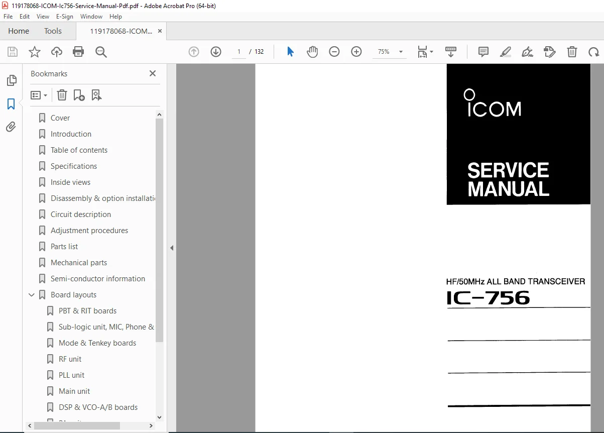
The table of contents on page 3 outlines the core service sections, including specifications, disassembly, circuit descriptions, adjustment procedures, parts list, board layouts, block diagrams, and voltage charts (TOC image reference).
📑 Contents / Bookmarks
SECTION 1 — Specifications (p.4)
Includes:
Frequency coverage (RX/TX bands)
Modes: USB, LSB, CW, RTTY, AM, FM
Receiver system (quadruple-conversion superheterodyne)
Sensitivity & selectivity tables
Power output levels (2–100W)
Spurious & carrier suppression
Antenna tuner specs (up to 3:1 SWR)
Current consumption & voltage ratings
SECTION 2 — Inside Views (p.5–6)
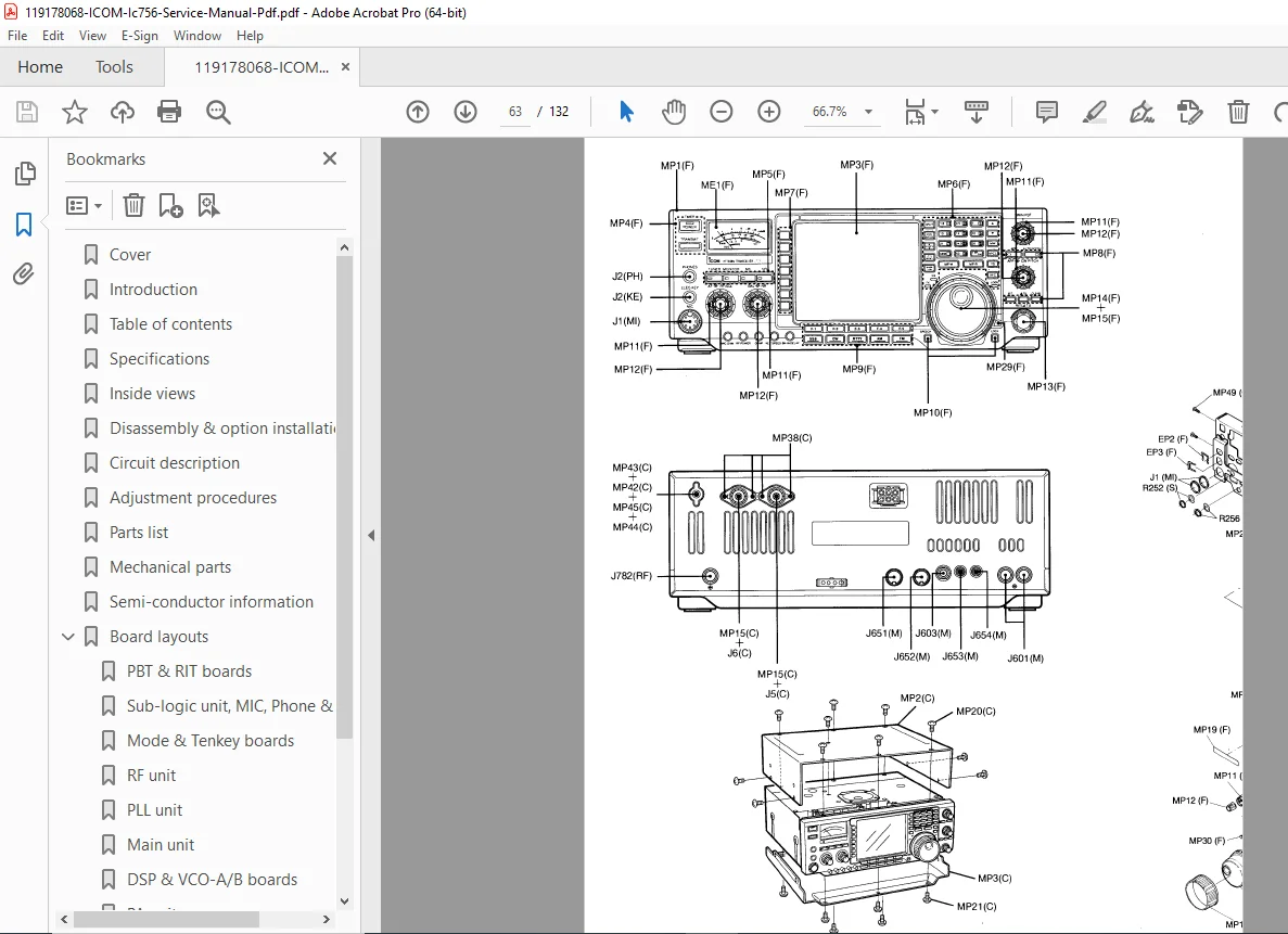
Top & bottom chassis views showing:
RF unit
MAIN unit
CTRL unit
FILTER unit
DSP board
PLL unit
ANT tuner unit
PA unit
(Labelled board diagrams in images)
SECTION 3 — Disassembly & Option Installations (p.7–8)
Procedures include:
Removing top & bottom covers
Installing UT-102 voice synthesizer unit
Optional IF filters installation
CR-502 high stability crystal unit
Reassembly precautions
Includes exploded-view diagrams & screw sequences.
SECTION 4 — Circuit Description (p.9–20)
Covers full RF & IF signal chain, including:
Receiver Circuits
RF switching & pre-amplifier circuits
RF band-pass filters
1st, 2nd, 3rd & 4th IF stages
DSP receiver processing board
S-meter & AGC circuits
Beltch filter & notch
AM & FM demodulator circuits
Signal-flow block diagrams are included throughout.
Transmitter Circuits
Microphone amplifier & speech compressor
IF amplifier & mixer circuits
RF unit & PA unit
Low-pass filter unit
ALC circuit & protection control
Temperature protection monitoring
APC transmitter gain control
PLL & Local Oscillator Circuits
LO synthesizer
2nd & 3rd LO generators
Marker circuit
Reference oscillators
PLL loop signal flow diagram
Antenna Tuner Circuits
Matching circuit relay logic
SWR detector
Motor control circuitry
CPU port allocation tables
Power Supply Circuits
PA unit voltage rails
Main unit distribution
CTRL / PLL supply lines
Logic & CPU Port Maps
Band selection data
Main CPU port allocation
Sub-logic CPU maps
I/O expander ports
Signal input tables…
📂 File Details
| Field | Details |
|---|---|
| Manual Name | Icom IC-756 Service Manual |
| Model | IC-756 HF/50MHz All-Band Transceiver |
| Format | PDF — factory service manual |
| Pages | 132 |
| Includes | Adjustments, RF/IF Circuits, PLL, DSP, ALC, PSU, Tuner, Logic Maps |
| Ideal For | Amateur radio service technicians & RF engineers |