IGT Game King Plus 19″ Upright Slot Machine Maintenance Manual PDF
Original price was: $95.00.$15.95Current price is: $15.95.
Official IGT maintenance procedures manual for the Game King Plus 19″ Upright slot machine (IGT Part No. 821-353-00). This comprehensive IGT Game King Plus service guide covers all 21 major assemblies — including logic module, video monitor & touchscreen, coin-in handling, bill acceptors, hopper, power supply, player panel switches, sound system, and more — essential for casino floor technicians and gaming equipment service personnel.
Description
IGT Game King Plus 19″ Upright Slot Machine Maintenance Manual PDF DOWNLOAD
Description
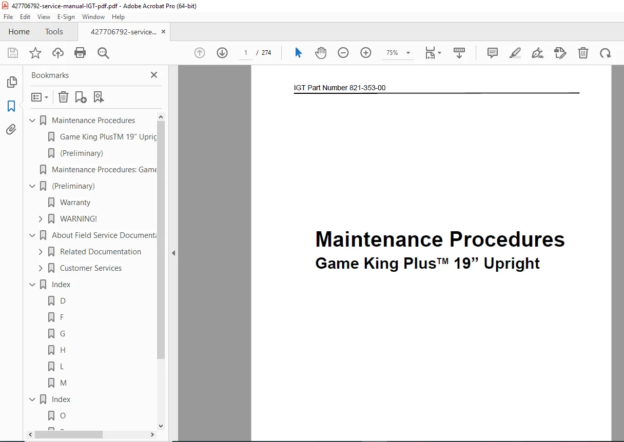
IGT Game King Plus™ 19″ Upright — Official Maintenance Procedures Manual
This is the official International Game Technology (IGT) Maintenance Procedures manual for the Game King Plus™ 19″ Upright slot machine, published October 2001 (IGT Part Number 821-353-00). Covering all 21 major system assemblies from coin-in handling to the logic module, this IGT Game King Plus repair guide is the definitive field service reference for casino technicians, gaming equipment service engineers, and slot machine mechanics responsible for maintaining, repairing, and verifying IGT Game King Plus upright video gaming machines.
📋 File Details
| Detail | Info |
|---|---|
| Manual Name | Maintenance Procedures: Game King Plus™ 19″ Upright |
| Manufacturer | International Game Technology (IGT), Reno, Nevada |
| IGT Part Number | 821-353-00 |
| Models Covered | Game King Plus™ 19″ Upright |
| Year | October 2001 |
| PDF Quality | Clean searchable digital PDF |
| Total Pages | 274 |
📚 Full Table of Contents — Section by Section
Section 1 — Introduction
- Machine Components overview with functional assembly descriptions
- Summary of all major assemblies: Bell, Bill Acceptor, Coin-In, Hopper, Logic Module, Power Supply, Video Monitor, Touchscreen, Sound System, Player Panel, Meters, Service Light, and more
- How to use IGT field service documentation series
Section 2 — Machine Enclosure
- 2.1 Locking Bar Assembly — removal and installation
- 2.2 Power Switch — removal and installation
- 2.3 Door Open and Service Lamp Switches
- 2.4 Service Lamp
- 2.5 Bill Acceptor Enclosure Components
Section 3 — Machine Door
- 3.1 Machine Door — removal and installation
- 3.2 Ticket/Coin Tray
- 3.3 Belly Door
- 3.4 Belly Door Latch
- 3.5 Belly Panel
- 3.6 Bill Acceptor Light Barrier/Entry Bezel
- 3.7 Monitor Mask
Section 4 — Optic Door-Open Sensor
- 4.1 Routine Maintenance
- 4.2 Removal
- 4.3 Installation
- 4.4 Functional Verification
Section 5 — Lorenzo Player Panel Switches
- 5.1 Switch Routine Maintenance
- 5.2 Switch Adjustments
- 5.3 Switch Removal
- 5.4 Switch Disassembly and Assembly
- 5.5 Switch Installation
- 5.6 Switch Functional Verification
Section 6 — Coin-In Handling
- 6.1 Coin Handling Component Arrangement
- 6.2 Coin-In Assembly Routine Maintenance
- 6.3 Coin Comparator Adjustments
- 6.4 Single-Denomination Electronic Coin Comparator
- 6.5 Multiple-Denomination Electronic Coin Acceptor
- 6.6 Coin-In Assembly Removal
- 6.7 Coin-In Disassembly and Assembly
- 6.8 Coin-In Assembly Installation
- 6.9 Sample Coin procedures
- 6.10 Denomination Change
- 6.11 Coin-In Functional Verification
Section 7 — JCM WBA Series Bill Acceptor
- 7.1 WBA Overview
- 7.2 Bill Acceptor Routine Maintenance
- 7.3 Bill Acceptor DIP Switch Settings
- 7.4 Sensor and Transport Assembly
- 7.5 Cash Box/Stacker Assembly
- 7.6 Bill Acceptor Functional Verification
Section 8 — Mars (MEI) Bill Acceptors
- 8.1 Introduction
- 8.2 Routine Maintenance
- 8.3 Sensor and Transport Assembly
- 8.4 Cash Box/Stacker Assembly
- 8.5 Bill Acceptor Functional Verification
Section 9 — Side Eject Pinwheel Hopper
- 9.1 Pinwheel Hopper Removal and Installation
- 9.2 Routine Maintenance
- 9.3 Probe Installation and Jumper Settings
- 9.4 Bowl Disassembly and Assembly
- 9.5 Motor Removal and Installation
- 9.6 Main Housing Disassembly and Assembly
- 9.7 Chassis Disassembly and Assembly
- 9.8 Pinwheel Hopper Functional Verification
Section 10 — Side Eject Holeywheel Hopper
- 10.1 Holeywheel Hopper Removal and Installation
- 10.2 Routine Maintenance
- 10.3 Probe Installation and Jumper Settings
- 10.4 Bowl Disassembly and Assembly
- 10.5 Motor Removal and Installation
- 10.6 Main Housing Disassembly and Assembly
- 10.7 Chassis Disassembly and Assembly
- 10.8 Holeywheel Hopper Functional Verification
Section 11 — Power Supply and Distribution
- 11.1 Routine Maintenance
- 11.2 Power Distribution (fuse/circuit breaker, connector panel, service outlets)
- 11.3 DC Power Supply Removal and Installation
- 11.4 Power Supply and Distribution Functional Verification
Section 12 — Logic Module
- 12.1 Logic Module Routine Maintenance
- 12.2 Processor Tray
- 12.3 Processor Board Component Identification
- 12.4 Motherboard
- 12.5 Input/Output Boards (Cabinet I/O and Door I/O)
- 12.6 Logic Module Functional Verification
Section 13 — Video Monitor and Touchscreen
- 13.1 Video Monitor Routine Maintenance
- 13.2 Video Monitor Removal and Installation
- 13.3 Video Adjustments
- 13.4 Touchscreen Replacement
- 13.5 Touchscreen Calibration and Test
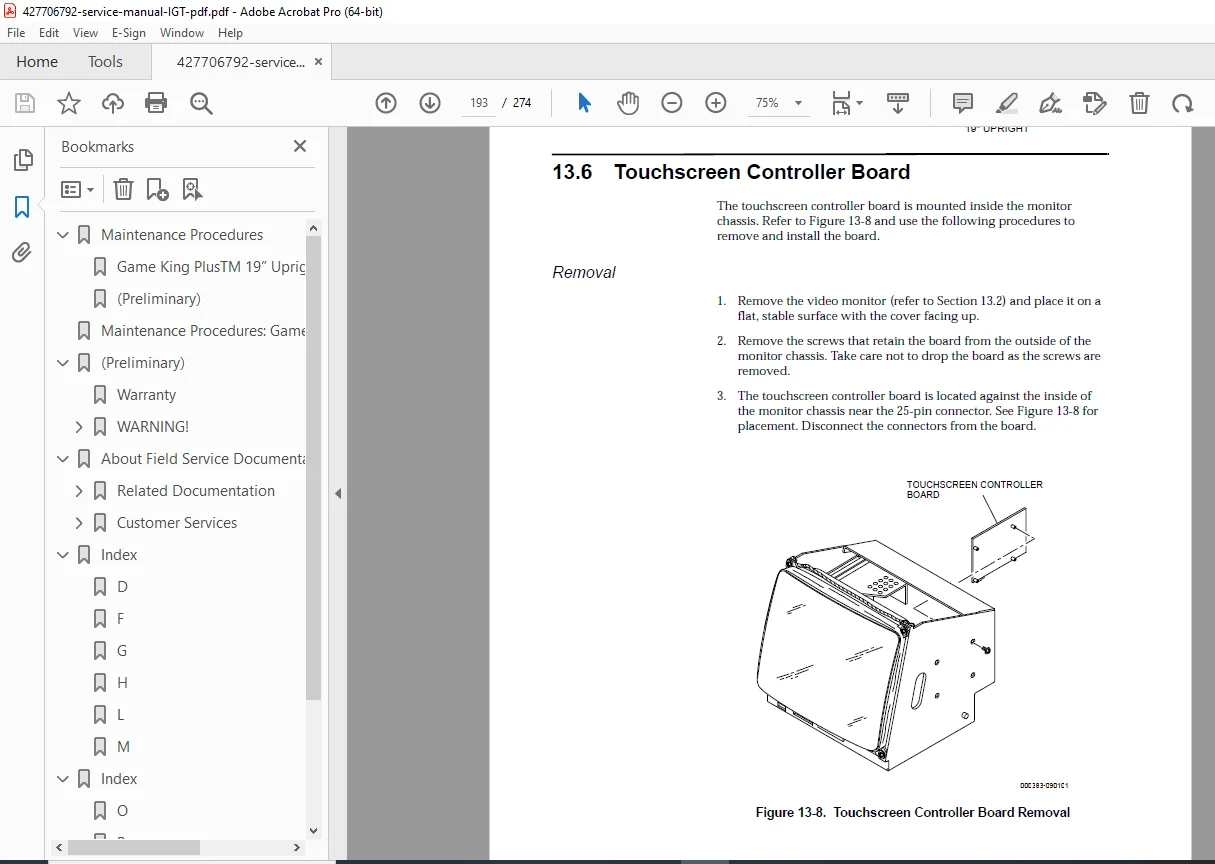
- 13.6 Touchscreen Controller Board
- 13.7 Video Monitor Functional Verification
Section 14 — Sound System
- 14.1 Speaker Removal and Installation
- 14.2 Multimedia Board Removal and Installation
- 14.3 Amplifier Assembly Removal and Installation
- 14.4 Sound System Functional Verification
Section 15 — Fluorescent Lighting
- 15.1 Belly Door Lighting
- 15.2 Top Box Lighting
Section 16 — Machine Glass
- 16.1 Routine Maintenance
- 16.2 Belly Glass Removal and Installation
- 16.3 Top Box Glass Removal and Installation
Section 17 — Slot Handle
- 17.1 Routine Maintenance
- 17.2 Slot Handle Removal
- 17.3 Slot Handle Mechanism Disassembly
- 17.4 Slot Handle Mechanism Assembly
- 17.5 Slot Handle Installation
- 17.6 Slot Handle Functional Verification
Section 18 — Meters
- 18.1 Meter Categories
- 18.2 Meter Removal and Installation
- 18.3 Meter Functional Verification
Section 19 — Fan
- 19.1 Machine Enclosure / Top Box Fan
- 19.2 Processor Tray Fan
Section 20 — Service Light (Candle)
- 20.1 Routine Maintenance
- 20.2 Service Light Lamp Replacement
- 20.3 Service Light Removal and Installation
- 20.4 Service Light Functional Verification
Section 21 — Bell
- Bell removal and installation
Back Matter
- Glossary — IGT-specific terms and acronyms
- Index — alphabetical topic index
🔧 Key Machine Assemblies Covered
| Assembly | Function |
|---|---|
| Processor Board | Controls internal video/game functions; coordinates machine operation via I/O system |
| Motherboard | Interface between processor, I/O boards, and machine components |
| Logic Module | Full cabinet I/O, door I/O, and processor tray system |
| 19″ Video Monitor | Displays game play, accounting, diagnostics and service screens |
| Touchscreen | Player input interface with calibration procedures |
| JCM WBA Bill Acceptor | Multi-denomination bill validation and stacking |
| Mars (MEI) Bill Acceptor | Alternative bill acceptor with full maintenance coverage |
| Pinwheel / Holeywheel Hopper | Coin payout mechanisms with probe and jumper settings |
| Coin-In Assembly | Coin verification, counting, routing with single and multi-denomination comparators |
| Player Panel Switches | Lorenzo player panel switch adjustment, disassembly, and verification |
| Power Distribution Module | Fuse/breaker, connector panel, and service outlets |
| Multimedia Sound Board | Speaker and amplifier system for game audio |
| Service Light (Candle) | Jackpot, attendant call, and mode indicator lamp |
📋 Related IGT Documentation Series
This manual is part of the complete IGT Game King Plus™ 19″ Upright field service library:
- Machine Specifications (p/n 821-356-XX)
- Machine Installation Procedures (p/n 821-287-XX)
- Troubleshooting: Game Machines (p/n 821-382-XX)
- Game Software: Game King® Products – Release 4 (p/n 821-321-XX)
- Mechanical Parts: Game King Plus™ 19″ Upright (p/n 821-351-XX)
- Electronic Diagrams and Parts: Game King Plus™ 19″ Upright (p/n 821-352-XX)
- EZ Pay Hardware Supplement (p/n 821-220-XX)
💡 Why You Need This Manual
Casino downtime costs money every minute a machine is off the floor. This IGT Game King Plus maintenance manual gives you the exact step-by-step procedures — with routine maintenance schedules, disassembly sequences, functional verification tests, and DIP switch settings — for every serviceable component on the machine. Purchase now, download instantly, and get your Game King Plus back in service today.