International Biomedical AeroNOx Nitric Oxide System Service Manual PDF
Original price was: $95.00.$32.95Current price is: $32.95.
Official technical service manual for the International Biomedical AeroNOx Portable Nitric Oxide Titration & Monitoring System. This AeroNOx repair manual covers full theory of operation, circuit-level descriptions (NO/NO2/O2 analyzers, delivery system, mass flow meter), adjustment procedures, preventive maintenance, troubleshooting symptoms & solutions, sensor replacement (NO, NO2, O2), pump cleaning, circuit schematics, and complete parts list — for qualified biomedical equipment technicians.
Description
International Biomedical AeroNOx Nitric Oxide System Service Manual PDF DOWNLOAD
Description
International Biomedical AeroNOx — Official Technical Service Manual
This is the official technical service and repair manual for the International Biomedical AeroNOx Portable Nitric Oxide Titration & Monitoring System, Document No. 715-7001, Revision G (2013). Published by International Biomedical, Inc., Austin, Texas, USA, this 103-page manual is the definitive field-level service reference for biomedical equipment technicians, clinical engineers, and authorized service personnel responsible for maintaining, calibrating, troubleshooting, and repairing the AeroNOx to factory specifications.
The AeroNOx is a microprocessor-based, battery-operated medical device designed for continuous monitoring and delivery of inhaled Nitric Oxide (iNO) in clinical environments. It simultaneously measures and displays NO (0–100 ppm), NO₂ (0–12 ppm), and O₂ (5–100%) concentrations, while controlling the delivery flow rate of therapeutic nitric oxide gas.
📋 File Details
| Detail | Info |
|---|---|
| Manual Name | AeroNOx Portable NO Titration & Monitoring System Technical Manual |
| Document Number | 715-7001, Revision G |
| Manufacturer | International Biomedical, Inc. (Austin, TX, USA) |
| Year | 2013 |
| PDF Quality | Clean searchable digital PDF |
| Total Pages | 103 |
| File Size | ~11.3 MB |
| Regulatory | EN 60601-1 — Class I / Internally Powered, Continuous Operation |
📐 AeroNOx System Specifications
Analysis System
| Parameter | Specification |
|---|---|
| Gases Detected | Nitric Oxide (NO), Nitrogen Dioxide (NO₂), Oxygen (O₂) |
| NO Range / Resolution | 0–100 ppm / 1 ppm |
| NO₂ Range / Resolution | 0–12 ppm / 0.1 ppm |
| O₂ Range / Resolution | 5–100% / 0.1% |
| Sensor Accuracy — NO | ±1 ppm |
| Sensor Accuracy — NO₂ | ±0.1 ppm |
| Sensor Accuracy — O₂ | ±2% ± 2 counts |
| Device Accuracy — NO | ±2 ppm |
| Device Accuracy — NO₂/O₂ | ±2 ppm / ±3% |
| Sampling Rate — O₂ | 2.5 samples/sec |
| Sampling Rate — NO/NO₂ | 2 samples/sec |
| Sensor Response Time | NO <20 sec, NO₂ <30 sec, O₂ <30 sec (to 90–95%) |
| Long-Term Output Drift | <2% loss per month (all sensors) |
| Gas Sampling Rate | 150 cc/min ±15% |
| A/D Conversion | 12-bit, 8-sample averaging |
Delivery System
| Parameter | Specification |
|---|---|
| Inlet Pressure (Recommended) | 345 kPa (50 psi) |
| Inlet Pressure (Minimum) | 207 kPa (30 psi) |
| Inlet Pressure (Maximum) | 517 kPa (75 psi) |
| Flow Control | Manual precision metering valve (12-turn) |
| Flow Range | 0–2 L/min |
| Flow Display | 3½ digit LED |
| Flow Resolution / Accuracy | 10 ml/min / ±5% full scale |
| Mass Flow Meter | Brooks Model 5700 |
Electrical & Battery
| Parameter | Specification |
|---|---|
| Battery | Internal 6V sealed lead-acid, 4.2 Ah/20 hr |
| Operating Time | 5 hours on full charge |
| Charge Time | ~6 hours |
| Cycle Life | ~200 cycles |
| External Power Supply | Medical grade, 100–240V, 50–60 Hz, 1A max |
| Supply Output | +12V DC, 3.3A max |
| Microprocessor | Motorola MC68HC711E9, 8 MHz |
Physical & Environmental
| Parameter | Specification |
|---|---|
| Dimensions (H×W×D) | 25.4 × 30.5 × 12.7 cm (10×12×5 in) |
| Weight | ~5 kg (11 lbs) |
| Operating Temperature | +5°C to +40°C |
| Storage Temperature | -20°C to +40°C |
| Operating Altitude | Sea level to 3,800 m (12,000 ft) |
| Humidity | 0–93% non-condensing |
| EMC Standard | IEC 60601-1-2 |
| RF Emissions | CISPR 11 Group 1, Class B |
| ESD Immunity | ±6 kV contact / ±8 kV air |
📚 Full Table of Contents — Section by Section
Section 1 — Specifications
- Introduction — AeroNOx system overview (integrated NO delivery + NO/NO₂/O₂ monitoring)
- Accessories — standard accessories shipped with instrument (operating manual, medical-grade power cord, “NO Worries” connector pack, universal power supply, stainless steel hose with quick connect)
- Performance Conditions Table — complete analysis system, delivery system, and electrical specification tables
- Environmental Characteristics Table — temperature, altitude, humidity, vibration, shock, EMC ratings
- Physical Characteristics Table — dimensions and weight
- EMC Guidance Tables (4 tables):
- Manufacturer’s Declaration — Emissions (CISPR 11, IEC 61000-3-2/3-3)
- Manufacturer’s Declaration — Immunity (IEC 61000-4-2/4/5/8/11)
- Manufacturer’s Declaration — Conducted/Radiated RF Immunity (IEC 61000-4-6/4-3)
- Recommended RF Separation Distances (0.01W to 100W transmitters, 150 kHz to 2.5 GHz)
Section 2 — Theory of Operation
Introduction & General Description:
- Section organization, IC description conventions (digital logic, linear devices)
- General system description — analysis system gas path (sample inlet → needle valve → pressure transducer → pump → sensor manifold → exhaust)
- Delivery system description — NO high-pressure inlet → manual flow control valve → Brooks MFM → dual solenoid valves → delivery outlet
- Microprocessor system (Motorola MC68HC711E9, 8 MHz) — startup sequence, sleep/wake mode, ROM check, power supply sequencing
Front Panel Operation:
- Front panel displays (LCD: NO & NO₂; LED: O₂ & flow)
- Switch functions table — ALARM SILENCE, ZERO, POWER, LITE, BOTH SIMULTANEOUS and associated LCD messages
- Thumbwheel alarm settings (NO Hi/Low 00–99 ppm, NO₂ Hi 00–12 ppm)
- Hi-Hi alarm logic (5 ppm above NO Hi, 1 ppm above NO₂ Hi → automatic gas shutoff)
Battery, Charger & Battery Monitor:
- Sealed lead-acid 6V/4.2Ah battery circuit description
- Battery charge circuit (LM350T, D1, D2, VSTR1, TZ1), 7.7V charging voltage
- Battery level indication (filled ‘B’ → empty ‘B’ → “LOW BATTERY” @ 5.0V → “DATA INVALID/CONNECT CHARGER/NITRIC OFF” @ 4.9V → microprocessor reset @ 4.6V)
Error & Warning Messages Table:
- Complete message definitions: B (battery), plug graphic (AC), LOW BATTERY, DATA INVALID, CONNECT CHARGER, NITRIC OFF, NO/NO₂ ZERO FAILURE, ROM FAILURE
Analysis System — Sensor Circuit Descriptions:
- Electrochemical Sensor Principles — amperometric cell operation (SENSE/COUNTER/REFERENCE electrodes, potentiostatic circuit, NO oxidation and NO₂ reduction reactions)
- NO₂ Analyzer Circuit — simplified schematic (U10 current-to-voltage converter, U9 gain-of-2 inverter amplifier, U6 12-bit MAX190 A/D converter, 8-sample averaging at 8 samples/sec)
- NO Analyzer Circuit — biased operation (-300 mV bias via U8), U7 amplifier, U5 MAX190 A/D, bias maintained during power-off to ensure immediate startup readiness
- Temperature Effects — baseline behavior, zero shift with temperature change
- Pressure Effects — transient responses to sudden pressure changes
- Humidity Effects — continuous operation 15–90% RH, high/low humidity cell behavior, drying precautions
- Cell Handling — 8-point handling guidelines (pressure, membranes, electrolyte leaks, solvent vapor damage, storage)
- Oxygen Analyzer Circuit — self-powered diffusion-limited lead-air cell, Pb/O₂ reactions, U14 (LT1101 gain-of-10 amplifier), R56 span potentiometer, U25 200mV full-scale LED panel meter, 0–50mV cell output for 0–100% O₂
- Oxygen Linearity — S = K·ln[1/(1-C)] correction formula, max error ~0.5% at 10% O₂
- Carrier Gas Effects — molecular weight influence on diffusion rate (Graham’s Law)
- Cross Sensitivity — toxic gas cross-sensitivity data, CO₂ enhancement effect (<0.3%/1% CO₂)
- O₂ Cell Handling Precautions — storage (6 months max, 0–20°C), solvent vapor exposure, lead disposal
Sampling System Monitor:
- Differential pressure transducer circuit — pump control, obstructed line detection
- Pump control circuit (U7A/U7B TLC393 comparators, Q1/Q2/Q3 transistors, R17 pump speed pot, R24 cutoff point set, R26 offset adjust, R23/C20 pressure transducer smoothing)
- 0.5-second pump start-up sequence, normal operating voltage (~2.5V), obstruction shutdown and “Check Sample Line” LED activation
Delivery System Alarms & Mass Flow Meter:
- Dual solenoid valve sequencing (power-on bolus prevention, 1-second purge)
- BCD thumbwheel scanning, Hi-Hi alarm auto-shutoff logic
- Brooks Model 5700 MFM circuit — 0–5V signal → R48 scaling → U26 LED panel meter (0–2.00 L/min display), zero adjustment trimpot
Section 3 — Adjustment Procedures
Tools & Equipment Required (Table 3-1):
- Soldering iron (15–42W), Phillips/Square recess/blade screwdrivers, nut drivers (¼”, 5/16″, 3/8″), hex socket screwdrivers (3/32″–3/64″), 100 MHz oscilloscope, digital multimeter, diagonal cutters, needle nose pliers, ESD safe work surface & wrist strap, PLCC extraction tool, trimmer adjustment tools, water manometer (80 cmH₂O), gas flowmeter with precision valve (0–250 cc/min), sample line/hydrophobic filter/Nafion line, NO/NO₂/O₂/N₂ calibration gases, NO/NO₂ sensor stimulator, adjustable DC power supply (0–20V @ 2A)
Step-by-Step Adjustment Procedures:
- LCD Display Contrast — R43 trimmer adjustment (CW increase, CCW decrease)
- Mass Flow Meter Zero — Brooks Model 5700 trimpot (remove rubber plug, adjust to ‘0’ display)
- Mass Flow Meter Span Calibration — 5.00V input to J4 pin 4, R48 adjustment for 2.00 display; verification at 2.50V → 1.00 display
- NO Sensor Bias (-300 mV) — R35 potentiometer (serial numbers IV001–IV099 only; units IV100+ have fixed precision resistor), measurement at -300mV test points beside R35
- Oxygen Analyzer Circuit — R51 zero calibration (short J1-1 to J1-3), R56 span calibration (adjust for 20.9% in room air, cell output 11–15mV)
- Sampling System Circuit — 9-step procedure: R17 pump speed set (180–190 cc/min unrestricted, 172 cc/min metered), R24 cutoff set (pump stops at 50 cmH₂O water column, flow ~125 cc/min restricted), R26 offset set (1.95±0.05V at J5 pin 1 to pin 4 when tripped), precision metering valve lock nut
Section 4 — Maintenance
General Care, Cleaning & Inspection:
- Exterior and interior visual inspection procedures
- Cleaning precautions (no alcohol/ammonia cleaners; mild detergent and water on dampened cloth only)
- Interior inspection: pinched tubing, loose connectors, damaged PCBs, overheated components, fan check (fan runs on AC only during battery charging)
- Potentiometer care (sealed, non-serviceable; erratic calibration = replace)
- Battery care — deep discharge prevention, extended storage (>7 days: remove battery or leave on continuous charge), yearly replacement recommendation
Preventive Maintenance Schedule:
- Sensors — periodic calibration check every 1,000 hours or 6 months; sensor life ~18 months
- Battery — yearly replacement; never deep discharge; continuous AC charge preferred
- Power Supply Connection — medical grade only; IEC 60320-C14 inlet
- Potentiometers (NO, NO₂, O₂) — limited adjustment life; replace if erratic
- Power Supply Fan — check operation when external supply attached
- Periodic Adjustments — performance check every 1,000 hours or 6 months
Troubleshooting Technique (10-step methodology):
- Check control settings
- Check associated equipment and connections
- Visual check (wiring, connectors, PCBs, plumbing)
- Check instrument performance
- Isolate problem to a circuit
- Check power supplies (voltages, noise, ripple via oscilloscope)
- Check PCB/subassembly interconnections
- Check waveforms and voltages (A/D input voltages for NO/NO₂, O₂ amplifier output)
- Check individual components (transistors, diodes, ICs, resistors, capacitors — ESD precautions)
- Repair and adjust circuit
Troubleshooting Symptoms & Solutions (13 documented faults):
- Instrument won’t power on after extended storage (discharged battery, ESD damage)
- High NO readings on startup (NO sensor bias lost due to deep discharge — minimum 3-hour bias recovery)
- LCD shows AERONOX VX.X when off (battery dead)
- O₂ analyzer won’t calibrate to room air or 100% O₂ (sensor output, leak check, potentiometer, wiring)
- NO/NO₂ sensors very slow to respond (aging sensor, contamination, gas leaks, calibration gas shelf life)
- NO/NO₂ values won’t reach calibration values
- NO/NO₂ values won’t stabilize during calibration
- NO/NO₂ won’t respond to gas at all
- NO/NO₂ values drift during use
- NO₂ reads locked at 21 (sensor overexposed to >21 ppm — flush with air/O₂)
- NO sensor won’t return to zero (overexposure to >100 ppm NO)
Corrective Maintenance Procedures:
- Battery Replacement — removal and installation procedure (with battery connector location, Figure 4-1)
- NO and NO₂ Sensor Replacement — initial preparations, 4-screw case separation (Figure 4-2), NO₂ PCB removal (Figure 4-3/4-4), NO₂ cell removal (Figure 4-5), NO cell removal, case reassembly, bias stabilization time (2–3 hours initial, 3 weeks full)
- Oxygen Sensor Replacement — O₂ cell removal (Figure 4-6), installation and recalibration procedure
- Pump Cleaning Procedure — step-by-step pump disassembly (Figures 4-7 through 4-11): pump power cable connector, pressure sensor cable connector, pump base exposure, pump disassembly
- Sample Rate Adjustment Procedure — detailed 16-step procedure with equipment configuration diagram (Figure 4-12), metering valve set screw (Figure 4-13), locking nut (Figure 4-14), pump adjustment potentiometers (Figure 4-15), record form
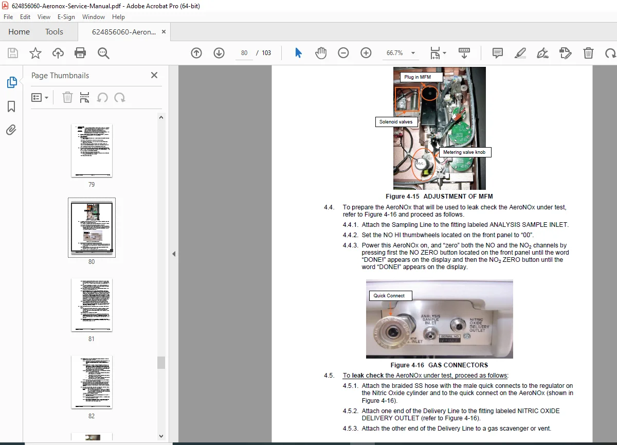
- MFM Flow Check / Plumbing Leak Test — step-by-step procedure (Figures 4-16 through 4-17: MFM adjustment, gas connectors, NO LPM display potentiometer), record form
Section 5 — Diagrams
- Schematic — AeroNOx Interconnection (full system block/interconnect diagram)
- Schematic — PCBA Switchboard, AeroNOx
- Schematic — PCBA Power Supply, AeroNOx
- Schematic — PCBA Main, AeroNOx
- Schematic — PCBA Power Line Filter, AeroNOx
Section 6 — Parts List
- Complete illustrated parts list for all AeroNOx assemblies and PCBAs
Section 7 — Appendix
- 3NF/F Nitric Oxide Sensor Data Sheet — performance characteristics, physical characteristics, temperature dependence curve, cross-sensitivity data, ordering information
- 3NDH Nitrogen Dioxide Sensor Data Sheet — performance characteristics, physical characteristics, temperature dependence curve, cross-sensitivity data, ordering information
- Recommended Practices — Gas Cylinder & Regulator Handling — maintaining NO calibration gas quality
- Contamination Effects of Air on NO₂ Formation in NO/N₂ Gas — storage and handling precautions for NO calibration gas mixtures
💡 Why You Need This Manual
Medical equipment failures in clinical settings are never acceptable. The AeroNOx technical service manual gives biomedical engineers the complete circuit-level detail, precise adjustment procedures, and systematic troubleshooting guidance needed to diagnose and repair this inhaled nitric oxide system with confidence — from sensor replacement to pump cleaning to PCB-level diagnostics. Purchase now, download instantly, and keep your AeroNOx in continuous ready-to-use condition.