Iseki SSM48 SRM48 SBC350 Parts Catalogue Manual – PDF DOWNLOAD
Original price was: $80.00.$19.95Current price is: $19.95.
Iseki SSM48 SRM48 SBC350 Parts Catalogue Manual – PDF DOWNLOAD
Description
Iseki SSM48 SRM48 SBC350 Parts Catalogue Manual – PDF DOWNLOAD
FILE DETAILS:
Iseki SSM48 SRM48 SBC350 Parts Catalogue Manual – PDF DOWNLOAD
Language : English
Pages :86
Downloadable : Yes
File Type : PDF
Size:20.9 mb
DESCRIPTION:
Iseki SSM48 SRM48 SBC350 Parts Catalogue Manual – PDF DOWNLOAD
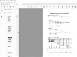
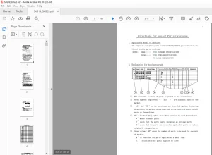
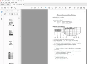
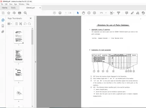
HOW TO USE THIS PARTS LIST
Explanations of symbols (column guidances)
A. KEY # B. The key number is to use as reference for locating part number (s) of illustrated drawing shown in the list. The index number is given to individual illustrations. The suffix of key number represents that the part number of the parts changes or modified according to historical sequence.
b. SPC ( Split Part Numbers)
There are part/parts originally with one part number but broken down into two or more parts and part numbers, due to technical reasons, which can be easily noticed at the KEY # with alphabet letters from A to Z. ( these parts are combinations of 2 or more parts in lieu of the original one
C.CHG ( Parts newly added or Modified)
To observe easily the differences between old and new parts list. If the column CHG is/are with: A : Parts newly added. C : Parts modified or chaged.
D.PART NUMBER
Every parts are coded according to its specifications, design and functions to describe the parts as references. There are parts with specific colour designed to specific country/countries as requirement, which can be destinguished after the part number with asterisk ( *) Mark. WHEN ORDERING REQUIRED COLOUR PARTS, BE SURE TO INDICATE COLOUR NUMBER OTHERWISE SHALL NOT TAKE ANY RESPON – SIBILITY AT ANY CIRCUMST ACES.
TABLE OF CONTENTS:
Iseki SSM48 SRM48 SBC350 Parts Catalogue Manual – PDF DOWNLOAD
Fig. 1 JO I NT (UN I VER SAL) SYSTEM ············ ……………………………………………….. ·· 1
F 2 COUNTER SYSTEM (for A) ………………………………………………………………. . 5
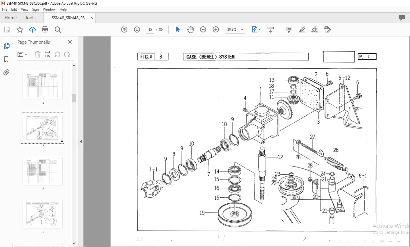
F 3 CASE (BEVEL) SYSTEM …………………………….. · ……………… · ……………. · ….. .. 7
Fig. 4 CASE (BEVEL) SYSTEM (for U) ………………………………………………………. . 9
F 5 METAL and BLADE SYSTEM ………………………………………………………………. . 11
Fig. 6 DECK (MOWER/ 48) and COVER SYSTEM ……………………………………………… ·· 13
Fig. 7 FORK (WHEEL) and WHEEL (GAUGE) SYSTEM ………………………………………. . 15
Fig. 8 LINK (FRONT) SYSTEM (for U) ………………………………………………………. . 17 -~-
Fig. 9 LINK (MAIN) SYSTEM (for U) ····•• …………………………………………………… . 19
Fig. 10 LINK (REAR) SYSTEM (for Ul ……………………………………………………. ..
Fig. 11 LINK (REAR) SYSTEM (for U18) …………………………………………………….. .
Fig. 12 MARKS …………………………………………………………………………………………. .
Fig.13 JOINT (UNIVERSAL) SYSTEM ……………………………………………………………. 27
Fig. 14 CASE (BEVEL) SYSTEM ……………………………………………………………………. 29
Fig. 15 METAL and BLADE SYSTEM ……………………………………………………………….. 31
Fig. 16 DECK (MOWER/ 48) and COVER SYSTEM ……………………………………………….. 33
Fig. 17 FORK (WHEEL) and WHEEL (GAUGE) SYSTEM ……………………………………….. 35
Fig. 18 MARKS ………………………………………………………………………………………….. 37
Fig. 19 FRAME (COLLECTOR) and COVER (JOINT) SYSTEM ………………………………… 39
Fig. 20 FRAME (BLOWER) and COVER (BELT) SYSTEM ………………………………………. 41
Fig. 21 CASING and COVER (DISCHARGE) SYSTEM …………………………………………… 43
Fig. 22 PIPE (COLLECTOR) and LEVER (COLLECTOR) SYSTEM …………………………… 45
Fig. 23 COLLECTOR (SIDE) and FRAME (OPEN) SYSTEM …………………………………… 47
Fig. 24 LOCK and BAG (COLLECTOR) SYSTEM …………………………………………………. 49
Fig. 25 COVER (SHOOTER) and HOSE (SHOOTER) SYSTEM …………………………………. 51
Fig. 26 PTO (REAR) SET (for 02) ……………………………………………………………… 53
Fig. 27 PTO (REAR) SET ·(for 01) ……………………………………………………………… 57
Fig. 28 SENSOR (COLLECTOR) and MARK SYSTEM …………………………………………….. 61
IMAGES PREVIEW OF THE MANUAL:
PLEASE NOTE:
- This is the SAME exact manual used by your dealers to fix your vehicle.
- The same can be yours in the next 2-3 mins as you will be directed to the download page immediately after paying for the manual.
- Any queries / doubts regarding your purchase, please feel free to contact [email protected]
S.M