Isuzu 6HH1 EVT (Euro 1) Emission & Electrical Diagnosis (Euro 1) F-Series Workshop Manual PDF
$19.95
Isuzu 6HH1 EVT (Euro 1) Emission & Electrical Diagnosis (Euro 1) F-Series Workshop Manual – PDF DOWNLOAD
Description
Isuzu 6HH1 EVT (Euro 1) Emission & Electrical Diagnosis (Euro 1) F-Series Workshop Manual – PDF DOWNLOAD
FILE DETAILS:
Isuzu 6HH1 EVT (Euro 1) Emission & Electrical Diagnosis (Euro 1) F-Series Workshop Manual – PDF DOWNLOAD
Language : English
Pages : 78
Downloadable : Yes
File Type : PDF
IMAGES PREVIEW OF THE MANUAL:
TABLE OF CONTENTS:
Isuzu 6HH1 EVT (Euro 1) Emission & Electrical Diagnosis (Euro 1) F-Series Workshop Manual – PDF DOWNLOAD
GE N ERAL DESCRIPTION 6Е-З
NOTES FOR WORКING ON ELECTRICAL ITEMS бЕ-З
SYMBOLS AND ABBREVIA TIONS бЕ-9
АВ В REVIA TIONS 6Е-1 О
PARTS FOR ELECTRICAL CIRCUIT бЕ-11
EVT (Electronic VariaЫe Timer) бЕ-12
Engine ECU Wiring Diagram бЕ-1 з
Component location бЕ-14
Engine бЕ-14
HARNESS LOCATION бЕ-15
Engine ECU Terminal Assignment бЕ-16
DIAG NOSTIC PROCEDU R Е бЕ-17
Detect DTC Ьу Warning Lamp (W/L) бЕ-18
Diagnosis TrouЫe Code ( DTC) 1i st бЕ-21
CONNECTOR INSPECTING PROCEDURE бЕ-23
Connector inspecting procedure бЕ-23
1 WHITE SMOKE (EXCESSIVE) бЕ-24
2 LACK OF POWER бЕ-26
3 Т АСНОМЕТЕ R АВ NORMALITY бЕ-28
4 W/L LAMP (DIAG LAMP) MALFUNCTION бЕ-30
Tech 2 Overview and applicaЫe model бЕ-33
Tech 2 Operation Manual бЕ-33
Diagnosis Strategy-Based Diagnostics бЕ-33
6Е-2 EMISSION AND ELECTRICAL DIAGNOSIS
PAGE
Reading Diagnostic TrouЫe Codes Using the Tech 2 Scan Tool бЕ-33
Tech 2 Features бЕ-33
Overview бЕ-35
Tech 2 бЕ-35
Tech 2 adapter бЕ-36
Location of DLC бЕ-37
DLC connection бЕ-38
Flow Chart for Snapshot relay (Plotting Graph) бЕ-42
Plotting Graph Flow Chart (Plotting graph after oЫaining vehicle information) бЕ-43
Trou Ыeshooting 6Е44
System Diagnosis бЕ-44
General Service I nformation бЕ-46
Р roЫems of serviceabllity 6 Е-46
Basic knowledge about the required tools бЕ-46
DTC 33 Memory ( RAM) error бЕ-48
DTC 54 Excessive high engine revolution error бЕ-49
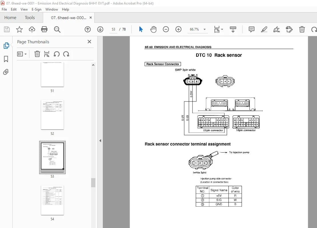
DTC 1 О Rack sensor бЕ-50
DTC 15 TDC sensor error бЕ-53
DTC 14 Timing sensor error бЕ-57
DTC 18 Timing Control Valve error бЕ-61
DTC 12 Timer Feed Back error бЕ-64
DTC 23 Coolant temperatu re sensor error бЕ-67
DESCRIPTION:
Isuzu 6HH1 EVT (Euro 1) Emission & Electrical Diagnosis (Euro 1) F-Series Workshop Manual – PDF DOWNLOAD
GENERAL DESCRIPTION:
The emission and electrical control system operates оп а twenty four volt power supply with negative ground polarity. Each wire in the vehicle is of а specific size and has an identifying colored insulation.
The harness uses а split corrugated tube to protect the wires from the elements. Each circuit consists of the following:
• Power source – The battery and the alternator. These colors are indicated in wiring diagrams and will help in tracing circuits and making proper connections. Wire size is determined Ьу load capacity and circuit length. Some wires are grouped together and taped. Such а grouping of wires is called а harness.
• Wires – То сапу electrical current through the circuit.
• Fuses – То protect the circuit against current overload.
• Relays – То protect voltage drop between the battery and the circuit parts and to protect the switch points against burning.
• Switches – То open and close the circuit.
• Load -Any device, such as а light or а motor, which converts the electrical current into useful work.
• Ground – То allow the current to flow back to the power source.
In this manual, such electrical device is classified Ьу system. For major parts shown оп the circuit based оп the
circuit diagram for each system, inspection and removal and installation procedures are detailed.
S.V 06/01/2025