Isuzu 6SD1-TC Engine Emission F&G Series Workshop Manual PDF
$28.95
Isuzu 6SD1-TC Engine Emission F&G Series Workshop Manual – PDF DOWNLOAD
Description
Isuzu 6SD1-TC Engine Emission F&G Series Workshop Manual – PDF DOWNLOAD
FILE DETAILS:
Isuzu 6SD1-TC Engine Emission F&G Series Workshop Manual – PDF DOWNLOAD
Language : English
Pages : 364
Downloadable : Yes
File Type : PDF
IMAGES PREVIEW OF THE MANUAL:
TABLE OF CONTENTS:
Isuzu 6SD1-TC Engine Emission F&G Series Workshop Manual – PDF DOWNLOAD
Chapter 1 Overview of IE system
1 Overviev ‘ and specitkation8 ot’ LE sy5tem 1-2
O”·crv·icw ofIE systcm 1-2
Specifications ofIE system 1-2
Electronically controlled fuel injection system
(common-rai I type) 1-3
VGS (VariaЫc Gcomctry Turbo Systcm) 1-5
Ch1tput of’ idle position signal to Ьтаk:е intensive
control u nit 1-7
Output of eng111e rotations to tachometer 1-7
Speed Limiter (SLD) 1-8
Exte -nal view of engine contr·ol unit 1-9
Enginc control unit input/output list 1-1 О
2 IE system schematic connection diagram L-12
3 Control unit/sensor/switch installing position 1-14
4 Functions ofinput/output and vehicle behavior
upo11 failщ·e (influence) 1-19
5 Othcrs 1-21
Object and procedure for accelemtor leaming
(lcarning of accclcrator pcdal idling position
and full-throttle position) 1-21
Q adjustment data 1-22
Chapter 2 Failure Diagnosis
1 Self-diagnosis ofIE system 2-2
Mcthod of chccking thc diagnostic trouЫc codc
Ьу SERVICE ENGINE SOON lamp 2-2
Emsing the diagnostic trouЫe code Ьу rnemory
сlеаг sv,,itch (connectoг) 2-3
Tcch 2 Opcration manual 2-6
2 Vehicle diagnostic procedure 2-16
3 Diagnostic trouЫc codcs list 2-19
Chapter 3 Functional diagnosis
Checking of SERVICE ENGINE SOON lamp
lighting circuit systcm (SERVICE ENGINE
SOON lamp does not tum ON) 3-2
Checking the SERVICE ENGINE SOON lашр
t1ashing control systeш (SERVICE ENGINE
SOON lamp does not flashing) 3-9
Checking the Tech П 3-13
Chccking thc cnginc starting systcm 3-17
Checking the power supply circuit 3-20
Checking the fuel system 3-24
Checking the intake system 3-26
Checking the staring system 3-28
Checking the exhaust system 3-32
Checking the parking switch 3-36
Idling speed cannot Ье adjusted 3-41
Idling speed cannot Ье decreased 3-43
Chapter 4 Checking procedure for each
diagnostic trouЫe code
IGI СМР sensor system trouЫe 4-3
1П1 СКР sensor system trouЫe 4-8
~ Atmospheric temperature sensor system
trouЫe 4-13
IDJ Watcr tcmpcraturc scnsor sy~icm trouЫc 4-19
~ Accelerator sensor system trouЫe 4-25
~ Vehicle speed sensor system trouЫe 4-31
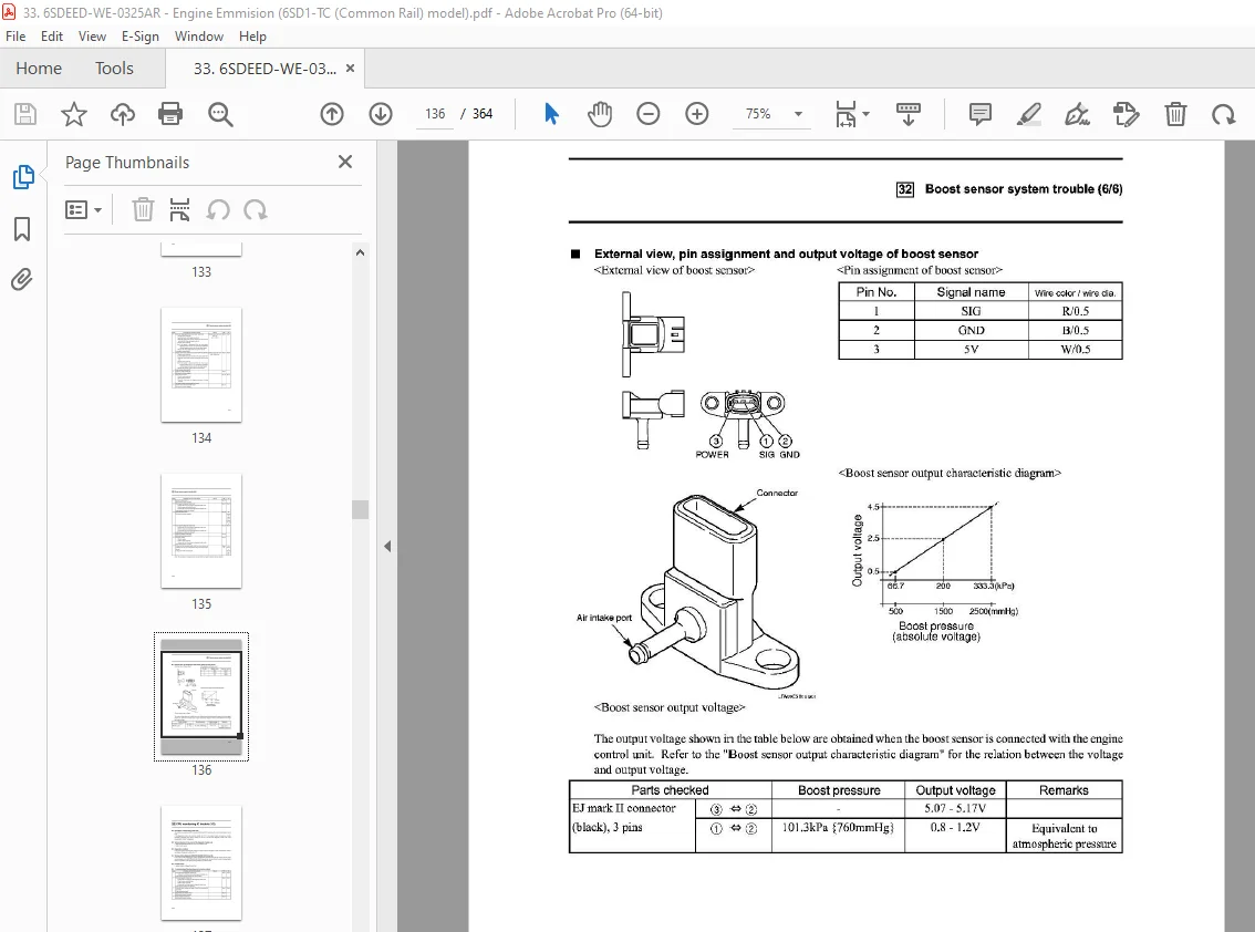
1§ Boosr sensor system trouЫe 4-38
[J] CPU monitoring IC trouЫe 4-44
1J3J A/D conversion eпor/charger·
circuit trouЫc 4-46
Н11 High boost trouЫe 4-48
~ Lo”v boost trouЬ!e 4-54
1П1 Atmospheric pressure sensor trouЪle 4-60
Ш Fuel pi·essщ·e sensor output fixed 4-62
Ш Common-гail pгessure trouЫe 4-67
Ш Common mil prcssure trouЫe
(рuшр excessive pressure feed) 4-7 4
1Ш1 Injector power systern trouЬ!e (Common J
”h1jector 1, 3, 5 Systems”) 4-81
Ш lnjector power system trouble (Comшon 2
“lnje(,1or 2, 4, 6 Systems”) 4-86
Ш Fuel teшperature sensortrouЫe 4-91
Ш PCVl system short circuit (battery and
power supply circuit) trouЫe 4-95
Ш PCV2 system short circuit (battery and
power supply ciгcuit) tгоuЫе 4-99
~ Supply pump no prcssuгc fccd or
pressure liшiter opemted 4-103
1п11 Pump no pressure feed
(Fuel outflov r) 4-108
Ш Accelemtor switch off trouЬ!e 4-113
Ш Accelerator switch оп tюuЫе 4-118
Ш Fucl prcssurc scnsorTrouЬ!c 4-123
Ш PCVl system hamess, short
(GND circuit) trouЫe 4-128
Ш PCV2 system hamess, short
(GND circuit) trouЪ!e 4-134
Ш No 1 cylinder No l inje(,101· drive
systcm trouЫc 4-140 m No 2 cylinder No 5 injector driye
system trouЫe 4-145
Ш No 3 cylinder No 3 inje(,101· drive
system trouЫe 4-150
Contents
~ No 4 cylinder No 6 injector drive
system trouЫe 4-155
Ш No 5 cylinder No 2 injectoг d1·ive
systcm trouЫc 4-160
Ш No 6 cylinder No 4 injector drive
system trouЫc 4-164
Ш Magnetic valve “А” drive
system trouЫe 4-168
Ш Magnetic valve “В” dгive
systcm trouЫc 4-175
Ш Magnetic valve “С” drive
system trouЫc 4-182
Ш Main rclay system trouЫe 4-189
Ш Starter switch trouЫe 4-194
Ш J:<‘ail-safe (Magnetic valve cut)
relay “А” system trouЫe 4-199
Ш PCV relay system trouЫe 4-203
Ш EOL data епоr 4-208
~ Excessive 11igh revolu tion епоr 4-210
Chapter 5 Checking Method for Symptom
Engine stall 5-2
Engine hunting, rough idle 5-5
Lack output po,ver of engine, insufficient
Ыоw up, pulsating combustion 5-8
White smoke (large) 5-12
Hlacksmokc (largc) 5-15
Chapter 6 Wiring check
1 Preface 6-2
Ideпtification ofwires 6-2
Wiring specifications 6-2
Fusc 6-3
Relay 6-3
Handliпg ot· co1111ectors and hamess 6-4
2 Vehicle wiring hamess 6-1 О
3 Wiring check 6-1 J
Engine control unit power sощ·се,
GND circuit 6-11
NE, G and fuel pressure sensor circuit 6-12
Boost, all spccd accclcrator scnsor circuit 6-13
Accelerator sensor and accelerator
switch circuit 6-14
Water temperature, fuel temperature апd
atmospheric temperature seruюr circuit 6-15
PCV (pump control Yalve),
PCV relay circuit 6-16
Injector (TWV) circuit 6-17
Magnetic Yalve, magnetic Yalve fail safe
relay circuit 6-18
Yehicle speed scщor ciгcuit 6-19
Starting circuit (key switch,
slow Ыоw fuse and fuse circuit) 6-20
Meter circuit (SERVICE ENGINE SOON
lamp, tachometer output) 6-21
Self-diagnosis cir·cuit (diagnosis S\\’itch,
mcmory clcar switch and Tcch 11
connecюr circuit) 6-22
Neutral circuit (Except automatic
transmission Yehicles) 6-23
Clutch switcl1 circuit 6-24
Brake switch circuit 6-25
Rc -crsc circuit 6-26
ldling control switch and idling control
selector switch circuit 6-27
Exhaust brake circuit 6-28
Chapter 7 How to use IE System lnspection
Tools
1 Tech 11 7-2
Techll 7-2
Chapter 8 Others
lnspection item chaгt for 1 1:: system
condition 8-2
AbbreYiation list 8-3
Pmgramming / upload / do”rnload fuel
delivery rate data 8-5
DESCRIPTION:
Isuzu 6SD1-TC Engine Emission F&G Series Workshop Manual – PDF DOWNLOAD
How to read this Manual:
This IE System TrouЫeshooting Manual describes the inspection procedure for the 1Е System (an electronically
contтollcd fucl injcction systcm ( comшon-rail)).
This ma11ual will l1elp you in correct and speedy service operatio11 for the IE System.
Chapter 1 Overview of IE system
• Specifications ofIE system
• Control mechanism ofIE system
• Jnput/output of 1~ sy~1cm
• Sensor & actuator installing position of each engine
Chapter 2 Failure diagnosis
• View of diagпostic trouЬ!e codes
• 1Е lamp does not light ON, or tl1e diagnosis mo11itor displays 110 data
• Contcnts of diagnostic trouЫc codcs
Chapter З Functional diagnosis
• Checking method for propcr opcration of 1Е Systcm or its functions
Chapter 4 Checking procedure for each diagnostic trouЫe code
• Chccking mcthod whcn а diagпostic trouЫc is displaycd
Chapter 5 Checking method for symptom (when по tгоuЫе code lights ON)
• When no diagпostic trouЬ!e code is displayed, how to know the position to Ье checked based on
the failure condition
Chapter 6 Wiring check
• Wiring connection condition
• Connecto1· inspection metl10d
• Wire arrangement
Chapter 7 How to use IE system inspection tools
• Ilow to use the wiring hamess for checking the wiring hamess checker, Tech II, and voltage
Chapter 8 Others
• Check sheet of 1Е system and simplified trouЫeshooting
S.V 06/01/2025