Isuzu Diesel Engine 4HK1 & 6HK1 Troubleshooting Manual ITE-3210 – PDF DOWNLOAD
Original price was: $78.95.$33.95Current price is: $33.95.
Isuzu Diesel Engine 4HK1 & 6HK1 Troubleshooting Manual ITE-3210 – PDF DOWNLOAD
Description
Isuzu Diesel Engine 4HK1 & 6HK1 Troubleshooting Manual ITE-3210 – PDF DOWNLOAD
DESCRIPTION:
Isuzu Diesel Engine 4HK1 & 6HK1 Troubleshooting Manual ITE-3210 – PDF DOWNLOAD
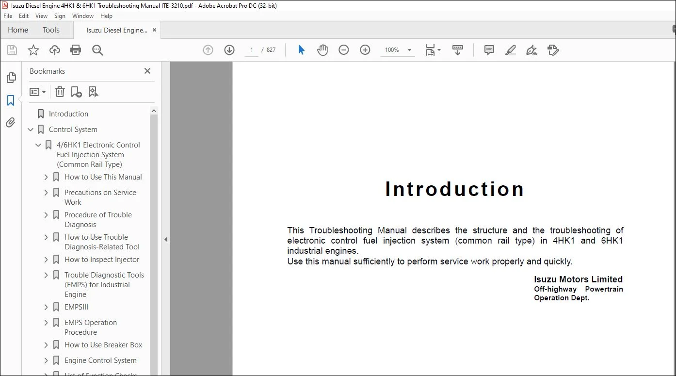
Introduction:
This Troubleshooting Manual describes the structure and the troubleshooting of
electronic control fuel injection system (common rail type) in 4HK1 and 6HK1
industrial engines.
Use this manual sufficiently to perform service work properly and quickly.
IMAGES PREVIEW OF THE MANUAL:
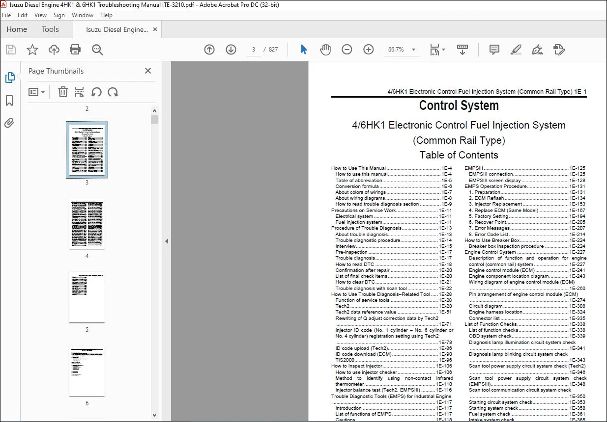
TABLE OF CONTENTS:
Isuzu Diesel Engine 4HK1 & 6HK1 Troubleshooting Manual ITE-3210 – PDF DOWNLOAD
Introduction…………………………………………………………………………………………………………………….. 1
Control System…………………………………………………………………………………………………………………… 3
4/6HK1 Electronic Control Fuel Injection System (Common Rail Type)…………………………………………………………………. 3
How to Use This Manual…………………………………………………………………………………………………….. 6
How to use this manual…………………………………………………………………………………………………. 6
Table of abbreviation………………………………………………………………………………………………….. 7
Conversion formula…………………………………………………………………………………………………….. 8
About colors of wirings………………………………………………………………………………………………… 9
About wiring diagrams………………………………………………………………………………………………….. 10
How to read trouble diagnosis section……………………………………………………………………………………. 11
Precautions on Service Work………………………………………………………………………………………………… 13
Electrical system……………………………………………………………………………………………………… 13
Fuel injection system………………………………………………………………………………………………….. 13
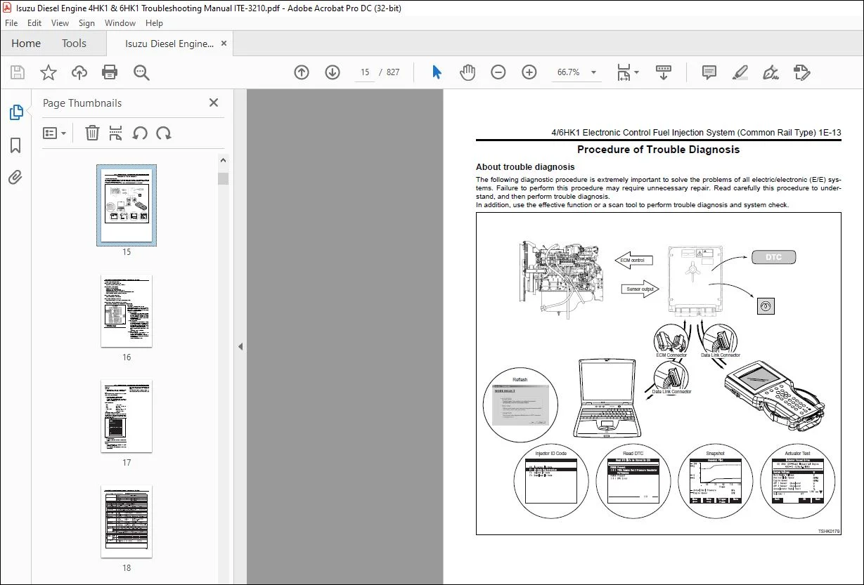
Procedure of Trouble Diagnosis……………………………………………………………………………………………… 15
About trouble diagnosis………………………………………………………………………………………………… 15
Trouble diagnostic procedure……………………………………………………………………………………………. 16
Interview…………………………………………………………………………………………………………….. 17
Pre-inspection………………………………………………………………………………………………………… 19
Trouble diagnosis……………………………………………………………………………………………………… 19
How to read DTC……………………………………………………………………………………………………….. 20
Confirmation after repair………………………………………………………………………………………………. 22
List of final check items………………………………………………………………………………………………. 22
How to clear DTC………………………………………………………………………………………………………. 23
Trouble diagnosis with scan tool………………………………………………………………………………………… 24
How to Use Trouble Diagnosis-Related Tool……………………………………………………………………………………. 30
Function of service tools………………………………………………………………………………………………. 30
Tech2………………………………………………………………………………………………………………… 30
Tech2 data reference value……………………………………………………………………………………………… 53
Rewriting of Q adjust correction data by Tech2……………………………………………………………………………. 73
Injector ID code (No. 1 cylinder – No. 6 cylinder or No. 4 cylinder) registration setting using Tech2…………………………… 80
ID code upload (Tech2)…………………………………………………………………………………………………. 88
ID code download (ECM)…………………………………………………………………………………………………. 92
TIS2000………………………………………………………………………………………………………………. 98
How to Inspect Injector…………………………………………………………………………………………………….108
How to use injector checker……………………………………………………………………………………………..108
Method to identify using non-contact infrared thermometer…………………………………………………………………..112
Injector balance test (Tech2, EMPSIII)……………………………………………………………………………………118
Trouble Diagnostic Tools (EMPS) for Industrial Engine………………………………………………………………………….119
Introduction…………………………………………………………………………………………………………..119
List of functions of EMPS……………………………………………………………………………………………….119
Cautions………………………………………………………………………………………………………………120
EMPS Component Parts……………………………………………………………………………………………………122
ECM (hardware) compatibility…………………………………………………………………………………………….123
ECM Variation………………………………………………………………………………………………………….123
System Requirements for EMPS Software (Recommended)………………………………………………………………………..123
EMPS (software) Setup Procedure………………………………………………………………………………………….124
EMPSIII…………………………………………………………………………………………………………………..127
EMPSIII connection……………………………………………………………………………………………………..127
EMPSIII screen display………………………………………………………………………………………………….130
EMPS Operation Procedure……………………………………………………………………………………………………133
1. Preparation…………………………………………………………………………………………………………133
2. ECM Reflash…………………………………………………………………………………………………………136
3. Injector Replacement…………………………………………………………………………………………………155
4. Replace ECM (Same Model)……………………………………………………………………………………………..169
5. Factory Setting……………………………………………………………………………………………………..196
6. Recover Point……………………………………………………………………………………………………….207
7. Error Messages………………………………………………………………………………………………………209
8. Error Code List……………………………………………………………………………………………………..216
How to Use Breaker Box……………………………………………………………………………………………………..226
Breaker box inspection procedure…………………………………………………………………………………………226
Engine Control System………………………………………………………………………………………………………229
Description of function and operation for engine control (common rail) system…………………………………………………229
Engine control module (ECM)……………………………………………………………………………………………..243
Engine component location diagram………………………………………………………………………………………..245
Wiring diagram of engine control module (ECM)……………………………………………………………………………..262
Pin arrangement of engine control module (ECM)…………………………………………………………………………….276
Circuit diagram………………………………………………………………………………………………………..310
Engine harness location…………………………………………………………………………………………………326
Connector list…………………………………………………………………………………………………………337
List of Function Checks…………………………………………………………………………………………………….340
List of function checks…………………………………………………………………………………………………340
OBD system check……………………………………………………………………………………………………….341
Diagnosis lamp illumination circuit system check…………………………………………………………………………..343
Diagnosis lamp blinking circuit system check………………………………………………………………………………345
Scan tool power supply circuit system check (Tech2)………………………………………………………………………..348
Scan tool power supply circuit system check (EMPSIII)………………………………………………………………………350
Scan tool communication circuit system check………………………………………………………………………………352
Starting circuit system check……………………………………………………………………………………………355
Starting system check…………………………………………………………………………………………………..360
Fuel system check………………………………………………………………………………………………………363
Intake system check…………………………………………………………………………………………………….367
Exhaust system check……………………………………………………………………………………………………368
EGR control system check………………………………………………………………………………………………..369
QOS system check……………………………………………………………………………………………………….372
List of Diagnostic Trouble Codes…………………………………………………………………………………………….377
List of diagnostic trouble codes…………………………………………………………………………………………377
DTC: P0087 (Flash code 227) Common rail low pressure fault (No pressure feed in supply pump)……………………………………424
DTC: P0088 (Flash code 118) Common rail pressure is abnormally high (1st or 2nd stage)…………………………………………434
DTC: P0089 (Flash code 151) Common rail pressure fault (Excessive pressure feed in supply pump)…………………………………440
DTC: P0090 (Flash code 247) SCV drive system open circuit, +B short or ground short……………………………………………445
DTC: P0107 (Flash code 71) Barometric pressure sensor circuit input is low (open circuit or ground short)………………………..451
DTC: P0108 (Flash code 71) Barometric pressure sensor circuit input is high (+5V short)………………………………………..458
DTC: P0112 (Flash code 22) Intake air temperature sensor fault (low voltage fault, GND short, short circuit)……………………..465
DTC: P0113 (Flash code 22) Intake air temperature sensor fault (high voltage fault, open circuit or short to power supply circuit)….471
DTC: P0117 (Flash code 23) Engine coolant temperature sensor fault (low voltage fault, GND short, short circuit)………………….478
DTC: P0118 (Flash code 23) Engine coolant temperature sensor input is high (open circuit or short to power supply)………………..484
DTC: P0182 (Flash code 211) Fuel temperature sensor fault (low voltage fault, GND short)……………………………………….492
DTC: P0183 (Flash code 211) Fuel temperature sensor fault (high voltage fault, open circuit or short to power supply circuit)………498
DTC: P0192 (Flash code 245) Common rail pressure sensor fault (low voltage fault, short circuit)………………………………..506
DTC: P0193 (Flash code 245) Common rail pressure sensor fault (high voltage fault)…………………………………………….512
DTC: P0201 (Flash code 271) Open circuit in injection nozzle #1 drive system………………………………………………….518
DTC: P0202 (Flash code 272) Open circuit in injection nozzle #2 drive system………………………………………………….525
DTC: P0203 (Flash code 273) Open circuit in injection nozzle #3 drive system………………………………………………….532
DTC: P0204 (Flash code 274) Open circuit in injection nozzle #4 drive system………………………………………………….539
DTC: P0205 (Flash code 275) Open circuit in injection nozzle #5 drive system………………………………………………….546
DTC: P0206 (Flash code 276) Open circuit in injection nozzle #6 drive system………………………………………………….551
DTC: P0219 (Flash code 543) Overrun………………………………………………………………………………………556
DTC: P0237 (Flash code 32) Boost pressure sensor fault (low voltage fault, open circuit)……………………………………….558
DTC: P0238 (Flash code 32) Boost pressure sensor fault (high voltage fault, short to power supply circuit, ground open circuit)…….565
DTC: P0335 (Flash code 15) Crank sensor fault (no signal)…………………………………………………………………..572
DTC: P0336 (Flash code 15) Crank sensor fault (signal fault)………………………………………………………………..579
DTC: P0340 (Flash code 14) Cam sensor fault (no signal)…………………………………………………………………….585
DTC: P0341 (Flash code 14) Cam sensor fault (signal fault)………………………………………………………………….592
DTC: P0380 (Flash code 66) Glow relay circuit fault………………………………………………………………………..599
DTC: P0381 (Flash code 67) Glow plug lamp circuit fault…………………………………………………………………….604
DTC: P0487 (Flash code 44) EGR position sensor fault……………………………………………………………………….609
DTC: P0488 (Flash code 45) EGR valve control fault…………………………………………………………………………615
DTC: P0522 (Flash code 294) Engine oil pressure sensor fault (low voltage fault, open circuit, ground short)……………………..621
DTC: P0523 (Flash code 294) Engine oil pressure sensor fault (high voltage fault, short to power supply, ground short)…………….627
DTC: P0601 (Flash code 53) ROM fault……………………………………………………………………………………..635
DTC: P0603 (Flash code 54) EEPROM fault…………………………………………………………………………………..637
DTC: P0606 (Flash code 51) CPU fault……………………………………………………………………………………..639
DTC: P0606 (Flash code 52) CPU monitoring IC fault…………………………………………………………………………641
DTC: P0611 (Flash code 34) Charge circuit fault (bank 1)……………………………………………………………………643
DTC: P0612 (Flash code 34) Charge circuit fault (bank 2)……………………………………………………………………646
DTC: P0650 (Flash code 77) Diagnosis lamp circuit fault…………………………………………………………………….649
DTC: P1093 (Flash code 227) No pump pressure feed………………………………………………………………………….654
DTC: P1095 (Flash code 225) Pressure limiter open………………………………………………………………………….665
DTC: P1112 (Flash code 295) Boost temperature sensor fault (low voltage fault, ground short)……………………………………676
DTC: P1113 (Flash code 295) Boost temperature sensor fault (high voltage fault, open circuit, short to power supply circuit)……….683
DTC: P1173 (Flash code 542) Overheat……………………………………………………………………………………..690
DTC: P1225 (Flash code 31) Idle UP/DOWN switch fault……………………………………………………………………….695
DTC: P1261 (Flash code 158) Injection nozzle common 1 drive system fault……………………………………………………..699
DTC: P1262 (Flash code 159) Injection nozzle common 2 drive system fault……………………………………………………..710
DTC: P1271 (Flash code 24) Accelerator sensor 1-2 comparison fault…………………………………………………………..721
DTC: P1277 (Flash code 24) Accelerator sensor 1 fault (low voltage fault)…………………………………………………….727
DTC: P1278 (Flash code 24) Accelerator sensor 1 fault (high voltage fault)……………………………………………………732
DTC: P1282 (Flash code 24) Accelerator sensor 2 fault (low voltage fault)…………………………………………………….737
DTC: P1283 (Flash code 24) Accelerator sensor 2 fault (high voltage fault)……………………………………………………742
DTC: P1345 (Flash code 16) Cam sensor out of phase…………………………………………………………………………747
DTC: P1625 (Flash code 416) Main relay fault………………………………………………………………………………752
DTC: P1630 (Flash code 36) A/D conversion fault……………………………………………………………………………758
DTC: P1631 (Flash code 55) Voltage fault in 5-V power supply 1………………………………………………………………760
DTC: P1632 (Flash code 55) Voltage fault in 5-V power supply 2………………………………………………………………764
DTC: P1633 (Flash code 55) Voltage fault in 5-V power supply 3………………………………………………………………768
DTC: P1634 (Flash code 55) Voltage fault in 5-V power supply 4………………………………………………………………772
DTC: P1635 (Flash code 55) Voltage fault in 5-V power supply 5………………………………………………………………776
DTC: U2104 (Flash code 84) CAN Bus fault………………………………………………………………………………….780
DTC: U2106 (Flash code 85) CAN timeout fault………………………………………………………………………………785
List of Trouble Symptom…………………………………………………………………………………………………….790
List of trouble symptom…………………………………………………………………………………………………790
Engine start failure……………………………………………………………………………………………………791
Engine stall…………………………………………………………………………………………………………..799
Engine hunting, rough idling…………………………………………………………………………………………….804
Engine output shortage………………………………………………………………………………………………….809
Exhaust gas contains a lot of white smoke…………………………………………………………………………………813
Exhaust gas contains a lot of black smoke…………………………………………………………………………………816
Noise…………………………………………………………………………………………………………………819
Fuel consumption deteriorates……………………………………………………………………………………………821
Oil consumption deteriorates…………………………………………………………………………………………….824
Special Tool………………………………………………………………………………………………………………826
List of special tool……………………………………………………………………………………………………826
Need help? Contact: [email protected]
https://vimeo.com/785700975
PLEASE NOTE:
- This is the same manual used by the dealers to diagnose and troubleshoot your vehicle
- You will be directed to the download page as soon as the purchase is completed. The whole payment and downloading process will take anywhere between 2-5 minutes
- Need any other service / repair / parts manual, please feel free to contact [email protected] . We still have 50,000 manuals unlisted
S.V