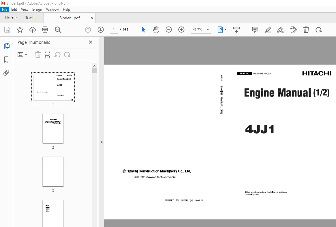
Isuzu Hitachi 4JJ1 Engine Workshop Manual – PDF DOWNLOAD
$34.95
Isuzu Hitachi 4JJ1 Engine Workshop Manual – PDF DOWNLOAD
Description
Isuzu Hitachi 4JJ1 Engine Workshop Manual – PDF DOWNLOAD
FILE DETAILS:
Isuzu Hitachi 4JJ1 Engine Workshop Manual – PDF DOWNLOAD
Language : English
Pages : 934
Downloadable : Yes
File Type : PDF
IMAGES PREVIEW OF THE MANUAL:
TABLE OF CONTENTS:
Isuzu Hitachi 4JJ1 Engine Workshop Manual – PDF DOWNLOAD
KM-4JJ1-E-00(1) 1
Engine Manual(1/2) 1
Introduction 2
General Contents 4
Control System 6
4JJ1 Electronic Control Fuel Injection System (Common Rail Type) 6
How to Use This Manual 11
How to use this manual 11
Table of abbreviation 12
About colors of wirings 14
About wiring diagrams 15
How to read trouble diagnosis section 16
Precautions on Service Work 18
Electrical system 18
Fuel injection system 18
Procedure of Trouble Diagnosis 20
About trouble diagnosis 20
Trouble diagnostic procedure 21
Interview 22
Pre-inspection 24
Trouble diagnosis 24
How to read DTC 25
Confirmation after repair 26
List of final check items 27
How to clear DTC 27
Trouble diagnosis with scan tool 28
How to Use Trouble Diagnosis-Related Tool 33
Function of service tools 33
Tech2 33
Tech2 data reference value 56
Rewriting of Q adjust correction data by Tech2 60
Injector ID code (No 1 cylinder – No 6 cylinder or No 4 cylinder) registration setting using Tech2 67
ID code upload (Tech2) 75
ID code download (ECM) 79
TIS2000 85
How to Inspect Injector 95
Injector balance test (Tech2, EMPSIII) 95
Trouble Diagnostic Tools (EMPS) for Industrial Engine 96
Introduction 96
List of functions of EMPS 96
Cautions 97
EMPS Component Parts 99
ECM (hardware) compatibility 100
ECM Variation 100
System Requirements for EMPS Software (Recommended) 100
EMPS (software) Setup Procedure 101
EMPSIII 104
EMPSIII connection 104
EMPSIII screen display 107
EMPS Operation Procedure 110
1 Preparation 110
2 ECM Reflash 112
3 Injector Replacement 130
4 Replace ECM (Same Model) 143
5 Factory Setting 168
6 Recover Point 179
7 Error Messages 181
8 Error Code List 188
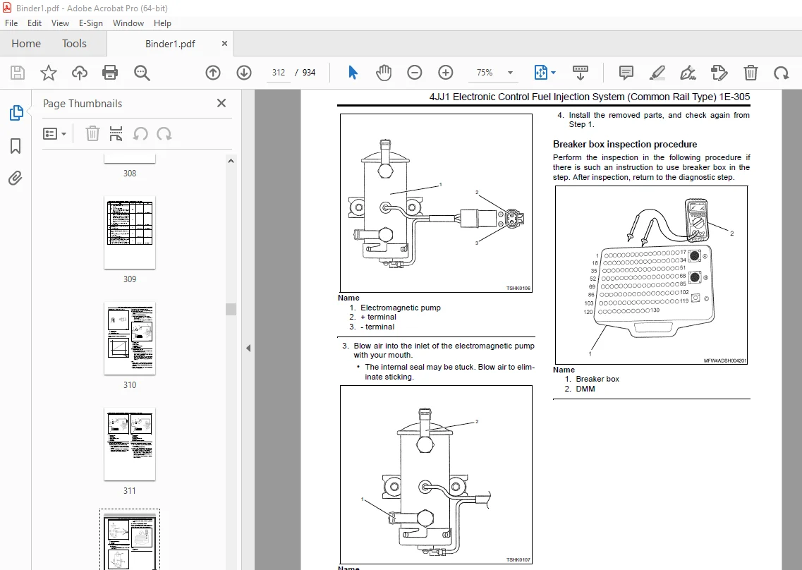
How to Use Breaker Box 198
Breaker box inspection procedure 198
Engine Control System 201
Description of function and operation for engine control (common rail) system 201
Engine control module (ECM) 215
Engine component location diagram 217
Wiring diagram of engine control module (ECM) 229
Pin arrangement of engine control module (ECM) 230
Circuit diagram 234
Engine harness location 247
Connector list 251
List of Function Checks 254
List of function checks 254
OBD system check 255
Diagnosis lamp illumination circuit system check 257
Diagnosis lamp blinking circuit system check 259
Scan tool power supply circuit system check (Tech2) 262
Scan tool power supply circuit system check (EMPSIII) 264
Scan tool communication circuit system check 266
Starting circuit system check 269
Starting system check 274
Fuel system check 277
Intake system check 281
Exhaust system check 281
EGR control system check 282
QOS system check 285
List of Diagnostic Trouble Codes 290
List of diagnostic trouble codes 290
DTC: P0087 (Flash code 227) Common rail low pressure fault (No pressure feed in supply pump) 303
DTC: P0088 (Flash code 118) Common rail pressure is abnormally high (1st or 2nd stage) 313
DTC: P0089 (Flash code 151) Common rail pressure fault (Excessive pressure feed in supply pump) 319
DTC: P0090 (Flash code 247) SCV drive system open circuit, +B short or ground short 324
DTC: P0107 (Flash code 71) Barometric pressure sensor circuit input is low (open circuit or ground short) 330
DTC: P0108 (Flash code 71) Barometric pressure sensor circuit input is high (+5V short) 336
DTC: P0112 (Flash code 22) Intake air temperature sensor fault (low voltage fault, GND short, short circuit) 342
DTC: P0113 (Flash code 22) Intake air temperature sensor fault (high voltage fault, open circuit or short to power supply circuit) 348
DTC: P0117 (Flash code 23) Engine coolant temperature sensor fault (low voltage fault, GND short, short circuit) 355
DTC: P0118 (Flash code 23) Engine coolant temperature sensor input is high (open circuit or short to power supply) 361
DTC: P0182 (Flash code 211) Fuel temperature sensor fault (low voltage fault, GND short) 369
DTC: P0183 (Flash code 211) Fuel temperature sensor fault (high voltage fault, open circuit or short to power supply circuit) 375
DTC: P0192 (Flash code 245) Common rail pressure sensor fault (low voltage fault, short circuit) 383
DTC: P0193 (Flash code 245) Common rail pressure sensor fault (high voltage fault) 389
DTC: P0201 (Flash code 271) Open circuit in injection nozzle #1 drive system 395
DTC: P0202 (Flash code 272) Open circuit in injection nozzle #2 drive system 400
DTC: P0203 (Flash code 273) Open circuit in injection nozzle #3 drive system 405
DTC: P0204 (Flash code 274) Open circuit in injection nozzle #4 drive system 410
DTC: P0219 (Flash code 543) Overrun 415
DTC: P0237 (Flash code 32) Boost pressure sensor fault (low voltage fault, open circuit) 417
DTC: P0238 (Flash code 32) Boost pressure sensor fault (high voltage fault, short to power supply circuit, ground open circuit) 424
DTC: P0335 (Flash code 15) Crank sensor fault (no signal) 431
DTC: P0336 (Flash code 15) Crank sensor fault (signal fault) 438
DTC: P0340 (Flash code 14) Cam sensor fault (no signal) 444
DTC: P0341 (Flash code 14) Cam sensor fault (signal fault) 451
DTC: P0380 (Flash code 66) Glow relay circuit fault 456
DTC: P0381 (Flash code 67) Glow plug lamp circuit fault 461
DTC: P0487 (Flash code 44) EGR position sensor fault 466
DTC: P0488 (Flash code 45) EGR valve control fault 471
DTC: P0522 (Flash code 294) Engine oil pressure sensor fault (low voltage fault, open circuit, ground short) 477
DTC: P0523 (Flash code 294) Engine oil pressure sensor fault (high voltage fault, short to power supply, ground short) 483
DTC: P0601 (Flash code 53) ROM fault 491
DTC: P0603 (Flash code 54) EEPROM fault 493
DTC: P0606 (Flash code 51) CPU fault 495
DTC: P0606 (Flash code 52) CPU monitoring IC fault 497
DTC: P0611 (Flash code 34) Charge circuit fault (bank 1) 499
DTC: P0612 (Flash code 34) Charge circuit fault (bank 2) 502
DTC: P0615 (Flash code 19) Starter cut relay circuit fault 505
DTC: P0650 (Flash code 77) Diagnosis lamp circuit fault 510
DTC: P1093 (Flash code 227) No pump pressure feed 515
DTC: P1095 (Flash code 225) Pressure limiter open 526
DTC: P1112 (Flash code 295) Boost temperature sensor fault (low voltage fault, ground short) 537
DTC: P1113 (Flash code 295) Boost temperature sensor fault (high voltage fault, open circuit, short to power supply circuit) 544
DTC: P1173 (Flash code 542) Overheat 551
DTC: P1225 (Flash code 31) Idle UP/DOWN switch fault 557
DTC: P1261 (Flash code 158) Injection nozzle common 1 drive system fault 561
DTC: P1262 (Flash code 159) Injection nozzle common 2 drive system fault 568
DTC: P1271 (Flash code 24) Accelerator sensor 1-2 comparison fault 575
DTC: P1277 (Flash code 24) Accelerator sensor 1 fault (low voltage fault) 581
DTC: P1278 (Flash code 24) Accelerator sensor 1 fault (high voltage fault) 586
DTC: P1282 (Flash code 24) Accelerator sensor 2 fault (low voltage fault) 591
DTC: P1283 (Flash code 24) Accelerator sensor 2 fault (high voltage fault) 596
DTC: P1345 (Flash code 16) Cam sensor out of phase 601
DTC: P1625 (Flash code 416) Main relay fault 605
DTC: P1630 (Flash code 36) A/D conversion fault 611
DTC: P1631 (Flash code 55) Voltage fault in 5V power supply 1 613
DTC: P1632 (Flash code 55) Voltage fault in 5V power supply 2 617
DTC: P1633 (Flash code 55) Voltage fault in 5V power supply 3 621
DTC: P1634 (Flash code 55) Voltage fault in 5V power supply 4 625
DTC: P1635 (Flash code 55) Voltage fault in 5V power supply 5 629
DTC: U2104 (Flash code 84) CAN Bus fault 633
DTC: U2106 (Flash code 85) CAN timeout fault 638
List of Trouble Symptom 643
List of trouble symptom 643
Engine start failure 644
Engine stall 652
Engine hunting, rough idling 657
Engine output shortage 662
Exhaust gas contains a lot of white smoke 666
Exhaust gas contains a lot of black smoke 669
Noise 671
Fuel consumption deteriorates 673
Oil consumption deteriorates 676
Special tool 678
List of Special Tool 678
KM-4JJ1-E-00(2) 680
Engine Manual(2/2) 680
Introduction 681
General Contens 683
General Information 685
General Information 688
Service Precautions 688
Reading the Model 692
General Information 692
Engine Mechanical (4JJ1) 699
Isuzu Diesel Engine (4JJ1) 701
Precautions on Service Work 701
Main Data and Specifications 706
Special tool 707
Engine Foot 708
Components 708
Removal 708
Installation 709
Cylinder Head Cover 711
Components 711
Removal 712
Installation 713
Torque Specifications 714
Intake Manifold 715
Components 715
Removal 715
Installation 716
Torque Specifications 718
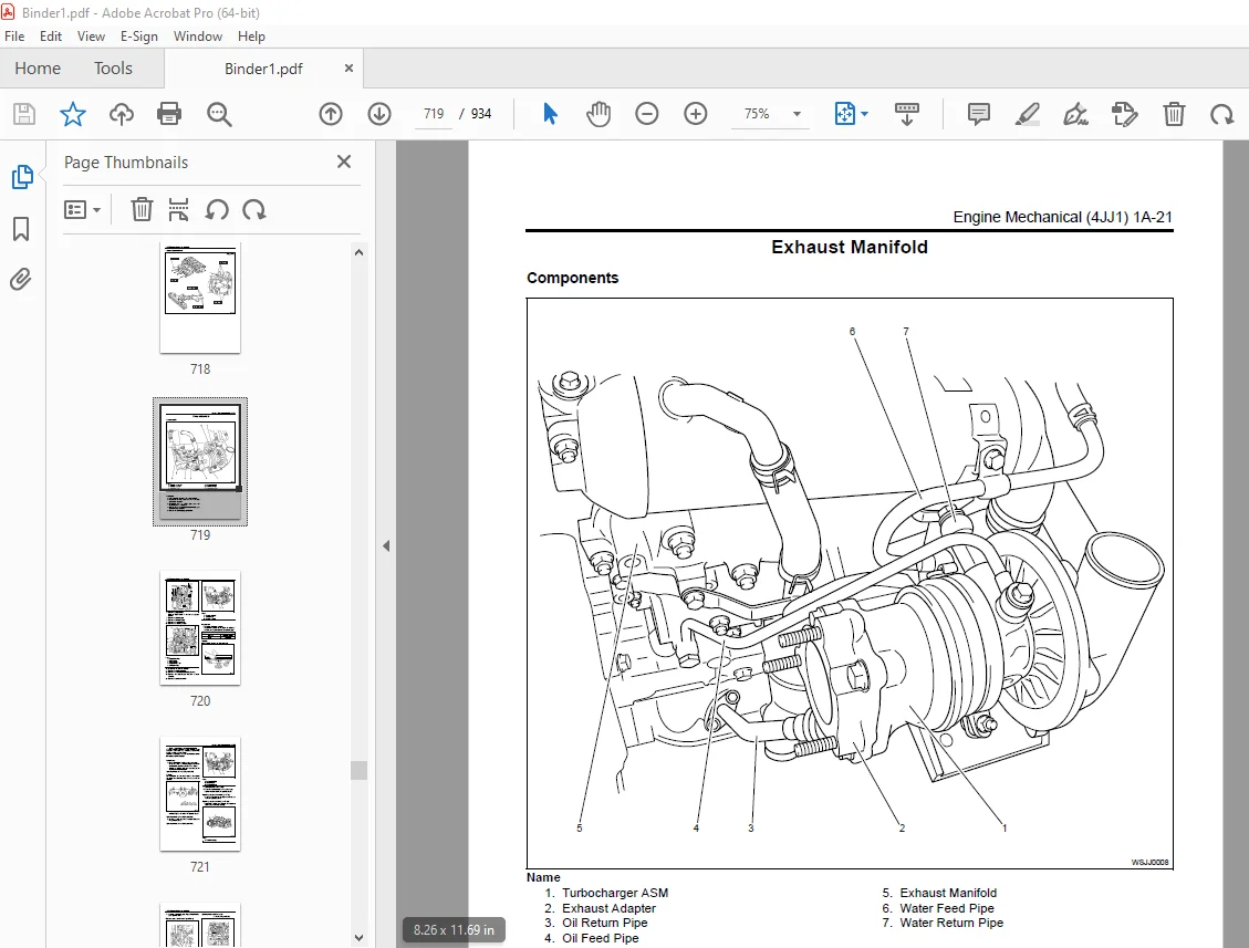
Exhaust Manifold 719
Components 719
Removal 719
Inspection 720
Installation 721
Torque Specifications 723
Timing Gear Train 724
Components 724
Removal 724
Disassembly 727
Reassembly 727
Inspection 728
Installation 729
Torque Specifications 733
Special Tool 733
Camshaft ASM 734
Components 734
Removal 735
Disassembly 736
Reassembly 738
Installation 739
Torque Specifications 741
Special Tool 741
Rocker Arm Shaft ASM 742
Components 742
Removal 742
Disassembly 743
Reassembly 745
Installation 745
Torque Specifications 746
Valve Stem Seal, Valve Spring 747
Components 747
Removal 747
Inspection 748
Installation 749
Special Tool 750
Cylinder Head 751
Components 751
Removal 751
Disassembly 756
Inspection 757
Reassembly 762
Installation 765
Torque Specifications 773
Special Tool 773
Piston, Connecting Rod 775
Components 775
Removal 775
Disassembly 776
Reassembly 782
Installation 783
Torque Specifications 785
Special Tool 785
Flywheel 786
Components 786
Removal 786
Inspection 787
Installation 787
Torque Specifications 789
Special Tool 789
Gear Case ASM 790
Components 790
Removal 790
Installation 791
Torque Specifications 792
Crankshaft Front Oil Seal 793
Components 793
Removal 793
Installation 794
Torque Specifications 796
Special Tool 796
Crankshaft Rear Oil Seal 797
Components 797
Removal 798
Installation 798
Torque Specifications 800
Special Tool 800
Crankshaft 801
Components 801
Removal 801
Disassembly 802
Reassembly 803
Inspection 803
Installation 807
Torque Specifications 810
Cylinder Block 811
Components 811
Removal 811
Inspection 812
Installation 814
Lubrication System 815
Precautions on Service Work 815
Functional Check 816
Special Tool 817
Oil Filter ASM 818
Components 818
Removal 818
Installation 819
Oil Port Cover ASM 820
Components 820
Removal 820
Installation 820
Oil Cooler 821
Components 821
Removal 821
Disassembly 822
Reassembly 823
Installation 823
Oil Relief Valve 825
Components 825
Removal 825
Installation 826
Crankcase, Oil Pan 828
Components 828
Removal 828
Disassembly 829
Reassembly 830
Installation 830
Torque Specifications 832
Oil Pump 833
Components 833
Removal 833
Disassembly 835
Reassembly 835
Inspection 835
Installation 837
Oil Pressure Switch 840
Components 840
Removal 840
Inspection 840
Installation 841
Cooling System 843
Cooling System 846
Precautions on Service Work 846
A List of Defective Phenomena 851
Main Data and Specifications 851
Water Pump 852
Components 852
Removal 852
Inspection 853
Installation 854
Torque Specifications 856
Thermostat 857
Components 857
Removal 857
Inspection 858
Installation 858
Drive Belt 859
Components 859
Inspection 859
Torque Specifications 860
Fan Clutch, Cooling Fan 861
Inspection 861
Fuel System 863
Fuel System 866
Precautions on Service Work 866
Special Tool 874
Fuel Filter ASM 875
Components 875
Removal 875
Installation 875
Fuel Filter Element 876
Removal 876
Installation 876
Special Tool 876
Fuel Injector 877
Components 877
Removal 878
Installation 878
Torque Specifications 881
Common Rail 882
Components 882
Removal 882
Installation 883
Torque Specifications 885
Fuel Supply Pump 886
Components 886
Removal 887
Installation 890
Torque Specifications 895
Engine Electrical 897
Service Precautions 900
General Procedure 900
Charging System 901
General Description 901
Inspection 902
Inspection 902
Generator 903
Removal 903
Installation 904
Torque Specifications 904
Specifications 905
Connector terminal 905
Internal connections 905
Disassembly of generator 906
Inspection and repair of generator 907
Performance test 909
Handling of generator 910
Trouble and action 911
Starting System 912
General Description 912
Service on the Machine: Starting System 913
Starter 914
Removal 914
Installation 915
Torque Specifications 915
Main Data and Specifications 916
Connections (Hitachi, Ltd ) 917
Inspection and repair of starter 918
Handling of starter 918
Trouble countermeasure 919
Preheating System 920
Glow Plug Replacement 920
Precautions on Service Work 920
A List of Defective Phenomena 920
Main Data and Specifications 921
Exhaust System and Turbocharger 923
EGR System 926
Precautions on Service Work 926
EGR Cooler 927
Components 927
Removal 928
Inspection 928
Installation 928
Torque Specifications 930
Exhaust System 931
A List of Defective Phenomena 931
Troubleshooting 931
Turbocharger 932
Turbocharger inspection 932
Inspection 932
Measurement Tool 933
Other Material 933
DESCRIPTION:
Isuzu Hitachi 4JJ1 Engine Workshop Manual – PDF DOWNLOAD
Introduction:
- This Manual describes the structure and the troubleshooting of electronic control
fuel injection system (common rail type) in 4JJ1 industrial engines. - Use this manual sufficiently to perform service work properly and quickly.
How to Use This Manual:
This manual describes about engine-related trouble diagnosis, and is closely related to the machine trouble diagnosis.
Always refer to both manuals for the trouble diagnosis.
This manual consists of the following contents. This section “How to use this manual” describes about abbreviations
and instructions to use this manual. Therefore, if you are familiar with Isuzu manuals, start with Precautions on service
work and Basic procedure of trouble diagnosis.
How to use this manual
• Table of abbreviation
• List of parts according to engine control specifications
• Wiring color code
• How to use wiring diagram
S.V 05/01/2025