Isuzu Hitachi 6WG1 Engine Troubleshooting Manual – PDF DOWNLOAD
$30.95
Isuzu Hitachi 6WG1 Engine Troubleshooting Manual – PDF DOWNLOAD
Description
Isuzu Hitachi 6WG1 Engine Troubleshooting Manual – PDF DOWNLOAD
FILE DETAILS:
Isuzu Hitachi 6WG1 Engine Troubleshooting Manual – PDF DOWNLOAD
Language : English
Pages : 580
Downloadable : Yes
File Type : PDF
IMAGES PREVIEW OF THE MANUAL:
TABLE OF CONTENTS:
Isuzu Hitachi 6WG1 Engine Troubleshooting Manual – PDF DOWNLOAD
Introduction 1
Control System 3
Engine Control (Electronic control fuel injection system (Common rail type)) 3
How to use this manual 5
Table of abbreviation 6
List of parts according to engine control specifications 7
About colors of wirings 8
About wiring diagrams 9
How to read trouble diagnosis section 10
Precautions on Service Work 12
Procedure of trouble diagnosis 13
Information: 14
Interview 15
Pre-inspection 17
Information: 17
Trouble Diagnosis 17
Description of terms 17
How to read DTC 18
Confirmation after repair 20
List of final check items 20
How to clear DTC 21
Trouble diagnosis with scan tool 22
About scan tool display 23
How to use trouble diagnosis-related tool 27
How to use Tech2 27
Components of Tech2 27
Each part of Tech2 28
Precautions on handling Tech2 29
Power supply 31
Check items before use 32
How to connect Tech2 32
Operation procedure 33
List of functions of Tech2 35
Diagnostic procedure 36
DTC application menu display screen 38
Data Display 39
Snapshot 40
Actuator test 44
Injector balance test 45
View captured data 47
Tool options 49
Rewrite setting of Q adjust correction data by Tech2 50
Injector ID code (No 1 cylinder – No 6 cylinder) registration setting using Tech2 57
ID code upload (Tech2) 65
ID code download (Tech2) 67
How to use TIS 2000 70
TIS 2000 installation procedure 70
How to display snapshot 72
Software download 77
How to Inspect Injector 80
How to use injector checker 80
Components of injector checker 80
Method to identify using non-contact infrared thermometer 84
How to use flash tool 86
Refer to related document 86
How to use breaker box 87
Breaker box inspection procedure 87
How to connect breaker box 87
Example of use for breaker box 88
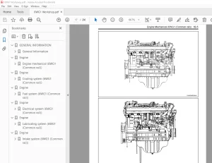
Engine Control System 90
Description of function and operation 90
About engine control (common rail) system 90
System control schematic diagram 90
Table of Input/Output 92
Electronic control fuel injection system (Common rail type) 92
System schematic diagram 93
Fuel system 94
EGR (Exhaust gas recirculation) 94
Idling control 96
Speed limit control 96
Engine speed output to tachometer 97
Preheating control 98
Engine Control Module (ECM) 98
Engine component location diagram 100
Supply pump 101
PCV (pressure control valve) 101
Fuel temperature (FT) sensor 102
G sensor 102
Common rail 103
Flow damper 103
Pressure limiter 104
Common rail pressure sensor 104
Injector 105
Engine coolant temperature (ECT) sensor 105
Crankshaft position (CKP) sensor 106
Engine oil pressure sensor 106
Accelerator position (AP) sensor 107
Intake air temperature (IAT) sensor 107
EGR position sensor 107
Boost pressure sensor 108
Boost temperature sensor 109
Diagnosis lamp 109
DLC (data link connector) 109
Diagnostic switch 109
Memory clear switch 109
Mode selector switch (1, 2, 3) 109
Wiring diagram of engine control module (ECM) 110
Pin arrangement of engine control module (ECM) 111
Circuit diagram 115
Main relay circuit 115
Starter for ECM control, glow circuit 116
Starter for safety relay, glow circuit 117
CAN, GND, DLC circuits 118
Indicator lamp, tachometer circuit 119
Injector circuit 120
PCV circuit 121
CKP sensor, vehicle speed sensor, fuel temperature sensor, engine coolant temperature sensor, engine oil pressure sensor circuit 122
Boost temperature sensor, boost pressure sensor circuit 123
G sensor, common rail pressure sensor, EGR circuit 124
Accelerator position sensor, barometric pressure sensor, intake air temperature sensor circuit 125
Idling selector switch, idle up switch, idle down switch, mode map switch circuit 126
Memory clear switch, engine stop switch circuit 127
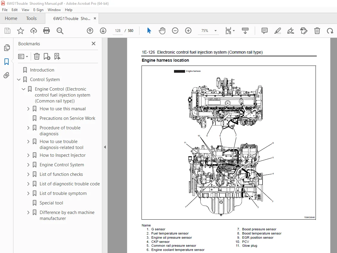
Engine harness location 128
H94/H95 connector 133
Connector list 134
List of function checks 137
OBD system check 138
Diagnosis lamp illumination circuit system check 140
Diagnosis lamp blinking circuit system check 142
Scan tool power supply circuit system check 145
Scan tool communication circuit system check 147
Starting circuit system check 150
Starting system check 156
Fuel system check 159
Intake system check 162
Exhaust system check 163
EGR control system check 164
QOS system check 167
List of diagnostic trouble code 172
DTC: P0088 (Flash code 118) Common rail pressure is abnormally high (1st or 2nd stage) 185
DTC: P0089 (Flash code 151) Common rail pressure fault (Excessive pressure feed in supply pump) 190
DTC: P0091/P1291 (Flash code 247/248) PCV circuit fault (PCV1 open circuit or GND short circuit / PCV2 open circuit or GND short circuit) 195
DTC: P0092/P1292 (Flash code 217/218) PCV circuit fault (PCV1+B short circuit / PCV2+B short circuit / PCV2+B short circuit) 201
DTC: P0107 (Flash code 71) Barometric pressure sensor circuit input is low (open circuit or ground short) 206
DTC: P0108 (Flash code 71) Barometric pressure sensor circuit input is high (+5V short) 213
DTC: P0112 (Flash code 22) Intake air temperature sensor fault (low voltage fault, GND short, short, short circuit) 220
DTC: P0113 (Flash code 22) Intake air temperature sensor fault (high voltage fault, open circuit or short to power supply circuit) 226
DTC: P0117 (Flash code 23) Engine coolant temperature sensor fault (low voltage fault, GND short, short circuit) 234
DTC: P0118 (Flash code 23) Engine coolant temperature sensor input is high (open circuit or short to power supply) 240
DTC: P0182 (Flash code 211) Fuel temperature sensor fault (low voltage fault, GND short) 248
DTC: P0183 (Flash code 211) Fuel temperature sensor fault (high voltage fault, open circuit or short to power supply circuit) 254
DTC: P0192 (Flash code 245) Common rail pressure sensor fault (low voltage fault, short circuit) 262
DTC: P0193 (Flash code 245) Common rail pressure sensor fault (high voltage fault, open circuit) 268
DTC: P0201 (Flash code 271) Open circuit in injection nozzle #1 drive system 275
DTC: P0202 (Flash code 272) Open circuit in injection nozzle #2 drive system 280
DTC: P0203 (Flash code 273) Open circuit in injection nozzle #3 drive system 285
DTC: P0204 (Flash code 274) Open circuit in injection nozzle #4 drive system 290
DTC: P0205 (Flash code 275) Open circuit in injection nozzle #5 drive system 295
DTC: P0206 (Flash code 276) Open circuit in injection nozzle #6 drive system 300
DTC: P0219 (Flash code 543) Overrun 305
DTC: P0237 (Flash code 32) Boost sensor pressure fault (low voltage fault, open circuit) 307
DTC: P0238 (Flash code 32) Boost pressure sensor fault (high voltage fault, short to power supply circuit, ground open circuit) 314
DTC: P0335 (Flash code 15) Crank sensor fault (no signal) 321
DTC: P0336 (Flash code 15) Crank sensor fault (signal fault) 327
DTC: P0340 (Flash code 14) G sensor fault (no signal) 333
DTC: P0341 (Flash code 14) G sensor fault (signal fault) 339
DTC: P0380 (Flash code 66) Glow relay circuit fault 345
DTC: P0381 (Flash code 67) Glow plug lamp circuit fault 350
DTC: P0487 (Flash code 44) EGR position sensor fault 355
DTC: P0488 (Flash code 45) EGR valve control fault 361
DTC: P0522 (Flash code 294) Engine oil pressure sensor fault (low voltage fault, open circuit, ground short) 367
DTC: P0523 (Flash code 295) Engine oil pressure sensor fault (high voltage fault, short to power supply, ground short) 373
DTC: P0601 (Flash code 53) ROM fault 381
DTC: P0603 (Flash code 54) EEPROM fault 383
DTC: P0606 (Flash code 51/52) CPU fault 385
DTC: P0611 (Flash code 34) Charge circuit fault (bank 1) 387
DTC: P0612 (Flash code 34) Charge circuit fault (bank 2) 390
DTC: P0615 (Flash code 19) Starter cut relay circuit fault 393
DTC: P0650 (Flash code 77) Diagnosis lamp circuit fault 399
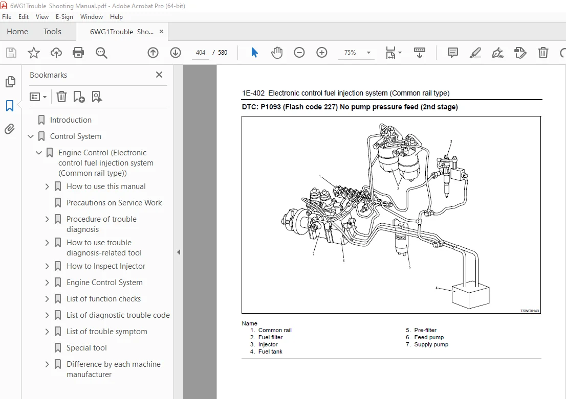
DTC: P1093 (Flash code 227) No pump pressure feed (2nd stage) 404
DTC: P1094 (Flash code 226) No pump pressure feed (1st stage) 413
DTC: P1095 (Flash code 225) Pressure limiter open 422
DTC: P1112 (Flash code 295) Boost temperature sensor fault (low voltage fault, ground short) 431
DTC: P1113 (Flash code 295) Boost temperature sensor fault (high voltage fault, open circuit, short to power supply circuit) 439
DTC: P1173 (Flash code 542) Overheat 446
DTC: P1225 (Flash code 31) Idle UP/DOWN switch fault 452
DTC: P1261 (Flash code 158) Injection nozzle common 1 drive system fault 456
DTC: P1262 (Flash code 159) Injection nozzle common 2 drive system fault 466
DTC: P1271 (Flash code 24) Accelerator sensor 1-2 comparison fault 476
DTC: P1277 (Flash code 24) Accelerator sensor 1 fault (low voltage fault) 482
DTC: P1278 (Flash code 24) Accelerator sensor 1 fault (high voltage fault) 487
DTC: P1282 (Flash code 24) Accelerator sensor 2 fault (low voltage fault) 492
DTC: P1283 (Flash code 24) Accelerator sensor 2 fault (high voltage fault) 497
DTC: P1345 (Flash code 16) Cam sensor out of phase 502
DTC: P1625 (Flash code 416) Main relay fault 507
DTC: P1630 (Flash code 36) A/D conversion fault 514
DTC: P1631 (Flash code 55) Voltage fault in 5-V power supply 1 516
DTC: P1632 (Flash code 55) Voltage fault in 5-V power supply 2 519
DTC: P1633 (Flash code 55) Voltage fault in 5-V power supply 3 522
DTC: P1634 (Flash code 55) Voltage fault in 5-V power supply 4 525
DTC: P1635 (Flash code 55) Voltage fault in 5-V power supply 5 528
DTC: U2104 (Flash code 84) CAN Bus fault 531
DTC: U2106 (Flash code 85) CAN timeout fault 536
List of trouble symptom 541
Engine start failure 542
Engine stall 546
Engine hunting, rough idling 550
Engine output shortage 554
Exhaust gas contains a lot of white smoke 559
Exhaust gas contains a lot of black smoke 562
Noise 565
Fuel consumption deteriorates 567
Oil consumption deteriorates 570
Special tool 572
Difference by each machine manufacturer 573
Hitachi Construction Machinery Co , Ltd 573
List of DTC 573
About wiring diagrams 576
DESCRIPTION:
Isuzu Hitachi 6WG1 Engine Troubleshooting Manual – PDF DOWNLOAD
Introduction:
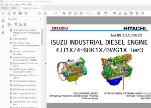
- This Troubleshooting Manual describes the structure of electronic control fuel injection
system (common rail type) in 6WG1 industrial engine. - Use this manual sufficiently to perform service work properly and quickly.
How to use this manual:
This manual describes about engine-related trouble diagnosis, and is closely related
to the machine trouble diagnosis. Always refer to both manuals for the trouble
diagnosis.
This manual consists of the following contents. This section “How to use this manual”
describes about abbreviations and instructions to use this manual. Therefore, if you
are familiar with Isuzu manuals, start with Precautions on service work and Basic
procedure of trouble diagnosis.
How to use this manual
• Table of abbreviation
• List of parts according to engine control specifications
• Wiring color code
• How to use wiring diagram
S.V 05/01/2025