Isuzu Trooper Holden Jackaroo 3.2L 3.5L Petrol & 3.0L 3.1L Diesel Shop Manual 1995-2005 – PDF Download
Original price was: $49.95.$29.95Current price is: $29.95.
Isuzu Trooper Holden Jackaroo 3.2L 3.5L Petrol & 3.0L 3.1L Diesel Shop Manual 1995-2005
Description
Isuzu Trooper Holden Jackaroo 3.2L 3.5L Petrol & 3.0L 3.1L Diesel Shop Manual 1995-2005
FILE DETAILS:
Isuzu Trooper Holden Jackaroo 3.2L 3.5L Petrol & 3.0L 3.1L Diesel Shop Manual 1995-2005
LANGUAGE:ENGLISH
PAGES:11798
DOWNLOADABLE:YES
FILE TYPE:PDF
ISUZU TROOPER HOLDEN JACKAROO 3.2L 3.5L PETROL & 3.0L 3.1L DIESEL SHOP MANUAL 1995-2005 – PDF DOWNLOAD:
IMAGES PREVIEW OF THE MANUAL:
DESCRIPTION:
Isuzu Trooper Holden Jackaroo 3.2L 3.5L Petrol & 3.0L 3.1L Diesel Shop Manual 1995-2005
1.Find the applicable section by referring to the table of contents on the introduction page of each manual.
2. In “Service Information”, an opening section of each manual, the troubleshooting, maintenance servicing, service data and/or information on special tools required for the service operations described in the next subsequent sections are arranged and compiled so concisely that you can see at a first glance.
3. Each section except the Service Information section is basically arranged in the following order of headings: General description On-vehicle service Unit repair
4. The service operations are in two groups: one is the “On-vehicle service” where operations can be directly performed on the vehicle, and the other is the “Unit repair” where the operations are done on the work bench after removing the unit from the vehicle.
5. Each service operation section begins with a disassembled view of unit or equipment, which is useful to find relative components, service procedure, availability and contents of repair kits, etc.
TABLE OF CONTENTS:
Isuzu Trooper Holden Jackaroo 3.2L 3.5L Petrol & 3.0L 3.1L Diesel Shop Manual 1995-2005
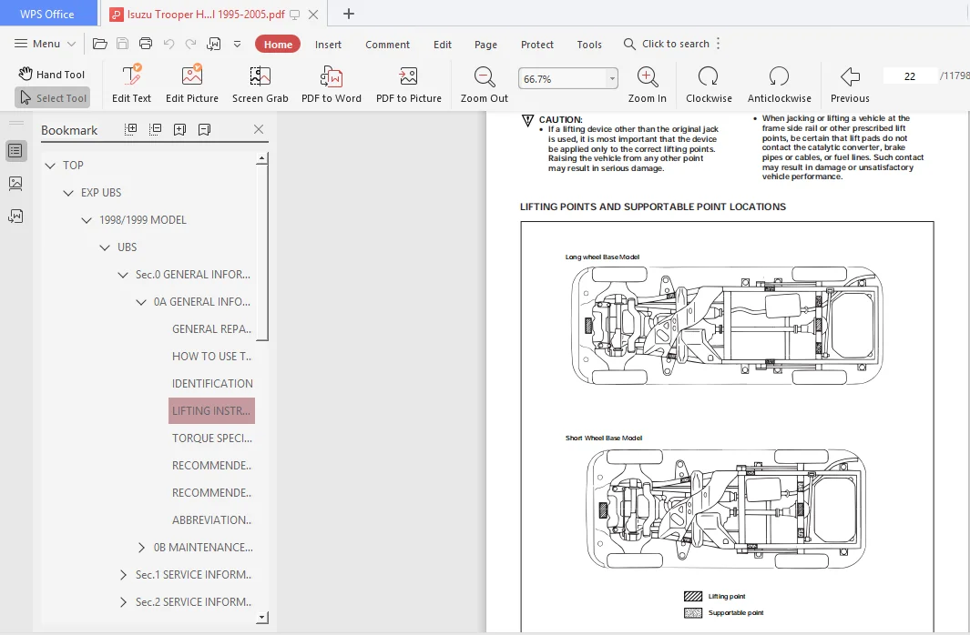
TOP..............................................................................................................................................    0
	EXP UBS......................................................................................................................................    2
		1998/1999 MODEL..........................................................................................................................    0
			UBS..................................................................................................................................    3
				Sec.0 GENERAL INFORMATION........................................................................................................   15
					0A GENERAL INFORMATION.......................................................................................................   15
						GENERAL REPAIR INSTRUCTIONS..............................................................................................   16
						HOW TO USE THIS MANUAL...................................................................................................   17
						IDENTIFICATION...........................................................................................................   20
						LIFTING INSTRUCTIONS.....................................................................................................   22
						TORQUE SPECIFICATIONS....................................................................................................   24
						RECOMMENDED LIQUID GASKET................................................................................................   25
						RECOMMENDED THREAD LOCKING AGENTS........................................................................................   25
						ABBREVIATIONS CHARTS.....................................................................................................   26
					0B MAINTENANCE AND LUBRICATION...............................................................................................   28
						MAINTENANCE SCHEDULE.....................................................................................................   29
						RECOMMENDED FLUIDS, LUBRICANTS AND FUELS.................................................................................   34
						OIL VISCOSITY CHART......................................................................................................   37
				Sec.1 SERVICE INFORMATION........................................................................................................   40
					00 SERVICE INFORMATION.......................................................................................................   40
						TROUBLESHOOTING..........................................................................................................   42
							CIRCUIT DIAGRAM......................................................................................................   43
							HEATING CYCLE TROUBLESHOOTING........................................................................................   55
							FAN CONTROL KNOB (FAN SWITCH)........................................................................................   56
								BLOWER MOTOR DOES NOT RUN........................................................................................   57
								BLOWER MOTOR DOES NOT RUN IN CERTAIN POSITION....................................................................   58
								BLOWER MOTOR DOES NOT STOP AT "OFF" POSITION.....................................................................   58
							CERAMIC HEATER.......................................................................................................   59
								CERAMIC HEATER DOES NOT OPERATE..................................................................................   60
								CERAMIC HEATER DOES NOT STOP.....................................................................................   61
							AIR CONDITIONING CYCLE TROUBLESHOOTING...............................................................................   62
								CHECKING REFRIGERANT SYSTEM WITH MANIFOLD GAUGE..................................................................   63
							MAGNETIC CLUTCH......................................................................................................   66
								6VD1/6VE1 ENGINE.................................................................................................   66
								4JG2 ENGINE......................................................................................................   70
								4JX1 ENGINE......................................................................................................   73
							CONDENSER FAN........................................................................................................   76
								CONDENSER FAN DOES NOT RUN.......................................................................................   77
								CONDENSER FAN DOES NOT STOP......................................................................................   78
							COMPRESSOR TROUBLESHOOTING...........................................................................................   79
							INDIVIDUAL INSPECTION................................................................................................   80
						MAIN DATA AND SPECIFICATIONS.............................................................................................   84
						FIXING TORQUE............................................................................................................   87
						SPECIAL TOOLS............................................................................................................   91
					1A HEATING AND VENTILATION...................................................................................................   96
						GENERAL DESCRIPTION......................................................................................................   97
							HEATER...............................................................................................................   97
							CONTROL LEVER ASSEMBLY...............................................................................................   98
							VENTILATION..........................................................................................................   98
							AIR SELECT KNOB......................................................................................................   99
							AIR SOURCE SELECT LEVER..............................................................................................   99
							FAN CONTROL KNOB.....................................................................................................   99
							TEMPERATURE CONTROL KNOB.............................................................................................   99
							CERAMIC HEATER.......................................................................................................  100
						ON-VEHICLE SERVICE.......................................................................................................  101
							HEATER UNIT..........................................................................................................  101
							HEATER CORE AND/OR MODE DOOR.........................................................................................  103
							HEATER MODE CONTROL LINK UNIT........................................................................................  105
							HEATER TEMPERATURE CONTROL LINK UNIT.................................................................................  107
							BLOWER ASSEMBLY......................................................................................................  109
							BLOWER LINK UNIT AND/OR MODE DOOR....................................................................................  111
							BLOWER MOTOR.........................................................................................................  113
							REAR HEATER DUCT, DEFROSTER NOZZLE AND VENTILATION DUCT..............................................................  115
							CENTER AND/OR SIDE VENT..............................................................................................  117
							CONTROL LEVER ASSEMBLY AND/OR CONTROL CABLES.........................................................................  119
							CONTROL PANEL ILLUMINATION BULB......................................................................................  122
							RESISTOR.............................................................................................................  123
							CERAMIC HEATER AND/OR FULL HOT SWITCH................................................................................  125
					1B AIR CONDITIONING..........................................................................................................  127
						GENERAL DESCRIPTION......................................................................................................  129
							AIR CONDITIONING REFRIGERANT CYCLE CONSTRUCTION......................................................................  129
							COMPRESSOR...........................................................................................................  130
							MAGNETIC CLUTCH......................................................................................................  131
							DUAL PRESSURE SWITCH.................................................................................................  132
							TRIPLE PRESSURE SWITCH...............................................................................................  132
							EXPANSION VALVE......................................................................................................  132
							EVAPORATOR...........................................................................................................  133
							ELECTRONIC THERMOSTAT................................................................................................  133
							REFRIGERANT LINE.....................................................................................................  133
							SERVICE CHARGE VALVES................................................................................................  133
							AIR CONDITIONING PARTS...............................................................................................  134
						ON-VEHICLE SERVICE.......................................................................................................  139
							PRECAUTIONS FOR REPLACEMENT OR REPAIR OF AIR CONDITIONING PARTS......................................................  139
							Compressor Assembly and Associated Parts.............................................................................  149
							CONDENSER ASSEMBLY (LHD V6 WITHOUT CONDENSER FAN)....................................................................  159
							CONDENSER FAN MOTOR..................................................................................................  161
							RECEIVER/DRIER.......................................................................................................  163
							PRESSURE SWITCH......................................................................................................  165
							EVAPORATOR ASSEMBLY..................................................................................................  168
							EVAPORATOR CORE AND/OR EXPANSION VALVE...............................................................................  170
							ELECTRONIC THERMOSTAT................................................................................................  173
							A/C SWITCH AND ILLUMINATION BULB.....................................................................................  174
							REFRIGERANT LINE.....................................................................................................  175
							REAR COOLER PARTS....................................................................................................  177
						FULL AUTOMATIC AIR CONDITIONING SYSTEM...................................................................................  186
						GENERAL DESCRIPTION......................................................................................................  186
							Full Automatic Air Conditioner Parts Configuration...................................................................  186
							CIRCUIT DIAGRAM......................................................................................................  188
							FUNCTIONS AND FEATURES...............................................................................................  200
							FULL AUTOMATIC AIR CONDITIONER BLOCK DIAGRAM.........................................................................  201
							AIR CONDITIONING PARTS...............................................................................................  202
							Control Panel Layout.................................................................................................  206
							Air Control Functions................................................................................................  207
							OPERATION AND FUNCTIONS OF CONTROL PANEL SWITCHES....................................................................  208
							OVERVIEW OF CONSTRUCTION, MOVEMENT AND CONTROL OF MAJOR PARTS OF FULL AUTOMATIC AIR CONDITIONER SYSTEM...............  210
							OVERVIEW OF AUTOMATIC CONTROL OF FULL AUTOMATIC AIR CONDITIONER......................................................  214
						TROUBLESHOOTING..........................................................................................................  218
							Troubleshooting, Its Overview and Procedures.........................................................................  218
							Performance and Movement checklist for Automatic Air Conditioner Related Parts.......................................  221
							TROUBLESHOOTING WITH SELF-DIAGNOSIS FUNCTION.........................................................................  223
						INSPECTION BY FAILED LOCATION............................................................................................  226
							Inspection of the Sensors............................................................................................  226
							Inspection of the Intake Actuator System.............................................................................  230
							Inspection of the Mix Actuator System................................................................................  233
							Inspection of the Mode Actuator System...............................................................................  236
							Inspection of the Fan Motor System...................................................................................  239
							Inspection of the Magnet Clutch System...............................................................................  244
							Inspection of the Air Conditioner Room Temperature Setup System......................................................  249
							INDIVIDUAL INSPECTION................................................................................................  250
						ON-VEHICLE SERVICE.......................................................................................................  252
							Power Transistor.....................................................................................................  252
							Automatic Heater/Air Conditioner Control Unit........................................................................  252
							In Car Sensor........................................................................................................  253
							Ambient Sensor.......................................................................................................  253
							Sun Sensor...........................................................................................................  254
							Electronic Thermostat................................................................................................  254
							Mode Actuator........................................................................................................  255
							MIX Actuator.........................................................................................................  255
							Intake Actuator......................................................................................................  256
					1D COMPRESSOR OVERHAUL.......................................................................................................  257
						GENERAL DESCRIPTION......................................................................................................  258
						GENERAL INFORMATION......................................................................................................  260
							COMPRESSOR OIL.......................................................................................................  260
						SERVICE PROCEDURE........................................................................................................  262
							DKV-14D TYPE COMPRESSOR..............................................................................................  262
							DKS-15CH TYPE COMPRESSOR.............................................................................................  266
							HD6 TYPE COMPRESSOR..................................................................................................  274
				Sec.2 SERVICE INFORMATION........................................................................................................  283
					00 SERVICE INFORMATION.......................................................................................................  283
						TROUBLESHOOTING..........................................................................................................  285
							GENERAL INFORMATION..................................................................................................  286
							GENERAL TROUBLESHOOTING..............................................................................................  286
							POWER STEERING SYSTEM................................................................................................  289
							POWER STEERING PUMP..................................................................................................  290
							STEERING COLUMN......................................................................................................  291
						MAIN DATA AND SPECIFICATIONS.............................................................................................  293
						SERVICE STANDARD.........................................................................................................  294
						SERVICING................................................................................................................  295
						FIXING TORQUE............................................................................................................  297
						SPECIAL TOOLS............................................................................................................  301
					2A FRONT END ALIGNMENT.......................................................................................................  303
						GENERAL DESCRIPTION......................................................................................................  304
							DEFINITION OF TERMS..................................................................................................  304
						ON-VEHICLE SERVICE.......................................................................................................  305
							INSPECTION...........................................................................................................  305
							TRIM HEIGHT ADJUSTMENT...............................................................................................  305
							CASTER ADJUSTMENT....................................................................................................  306
							CAMBER ADJUSTMENT....................................................................................................  306
							TOE-IN ADJUSTMENT....................................................................................................  307
							MAXIMUM STEERING ANGLE ADJUSTMENT....................................................................................  307
				Sec.3 SUSPENSION.................................................................................................................  389
					3C FRONT SUSPENSION..........................................................................................................  389
						GENERAL DESCRIPTION......................................................................................................  390
						ON-VEHICLE SERVICE.......................................................................................................  391
							SHOCK ABSORBER.......................................................................................................  391
							STABILIZER BAR.......................................................................................................  393
							TORSION BAR..........................................................................................................  395
							KNUCKLE..............................................................................................................  398
							UPPER CONTROL ARM....................................................................................................  402
							LOWER CONTROL ARM....................................................................................................  406
							UPPER BALL JOINT.....................................................................................................  410
							LOWER BALL JOINT.....................................................................................................  413
					3D REAR SUSPENSION; COIL SPRING..............................................................................................  416
						GENERAL DESCRIPTION......................................................................................................  417
						ON-VEHICLE SERVICE.......................................................................................................  418
							COIL SPRING..........................................................................................................  418
							SHOCK ABSORBER.......................................................................................................  421
							TRAILING LINK........................................................................................................  423
							CENTER LINK..........................................................................................................  425
							LATERAL ROD..........................................................................................................  427
							STABILIZER BAR.......................................................................................................  430
					3E WHEELS AND TIRES..........................................................................................................  432
						GENERAL DESCRIPTION......................................................................................................  433
						ON-VEHICLE SERVICE.......................................................................................................  434
							WHEELS...............................................................................................................  434
						UNIT REPAIR..............................................................................................................  435
							TIRES................................................................................................................  435
							WHEELS...............................................................................................................  436
							GENERAL BALANCE PROCEDURE............................................................................................  436
							BALANCING WHEEL AND TIRE.............................................................................................  437
				Sec.4 DRIVELINE/AXLE.............................................................................................................  438
					4A1 DIFFERENTIAL (FRONT).....................................................................................................  438
						Service Precaution.......................................................................................................  438
						Front Drive Axle.........................................................................................................  439
							Diagnosis............................................................................................................  439
						Pinion Shaft Oil Seal....................................................................................................  440
							Pinion Shaft Oil Seal and Associated Parts...........................................................................  440
							Removal..............................................................................................................  440
							Inspection and Repair................................................................................................  441
							Installation.........................................................................................................  441
						Front Drive Axle Assembly................................................................................................  442
							Front Drive Axle Assembly and Associated Parts.......................................................................  442
							Removal..............................................................................................................  442
							Installation.........................................................................................................  444
						Differential Assembly....................................................................................................  446
							Disassembled View....................................................................................................  446
							Disassembly..........................................................................................................  446
							Reassembly...........................................................................................................  449
						Differential Cage Assembly...............................................................................................  458
							Disassembled View....................................................................................................  458
							Disassembly..........................................................................................................  458
							Inspection and Repair................................................................................................  459
							Reassembly...........................................................................................................  460
							Main Data and Specifications.........................................................................................  462
							Special Tools........................................................................................................  465
					4A2A DIFFERENTIAL (Rear 220mm)...............................................................................................  468
						Service Precaution.......................................................................................................  468
						General Description......................................................................................................  469
						Diagnosis................................................................................................................  470
						Axle Housing.............................................................................................................  471
							Axle Housing and Associated Parts....................................................................................  471
							Removal..............................................................................................................  471
							Oil Seal Replacement.................................................................................................  472
							Installation.........................................................................................................  472
						Pinion Oil Seal..........................................................................................................  473
							Pinion Oil Seal and Associated Parts.................................................................................  473
							Removal..............................................................................................................  473
							Inspection and Repair................................................................................................  474
							Installation.........................................................................................................  474
						Differential Assembly....................................................................................................  475
							Differential Assembly and Associated Parts...........................................................................  475
							Removal..............................................................................................................  475
							Installation.........................................................................................................  476
							Disassembled View....................................................................................................  477
							Disassembly..........................................................................................................  478
							Reassembly...........................................................................................................  480
						Differential Cage Assembly...............................................................................................  488
							Disassembled View....................................................................................................  488
							Disassembly..........................................................................................................  488
							Inspection and Repair................................................................................................  489
							Reassembly...........................................................................................................  490
						Limited Slip Differential................................................................................................  492
							Disassembled View....................................................................................................  492
							Disassembly..........................................................................................................  493
							Inspection and Repair................................................................................................  493
							Reassembly...........................................................................................................  495
							Main Data and Specifications.........................................................................................  499
							Special Tools........................................................................................................  501
					4A2B DIFFERENTIAL (REAR 244mm)...............................................................................................  504
						Service Precaution.......................................................................................................  504
						General Description......................................................................................................  505
						Diagnosis................................................................................................................  506
						Axle Housing.............................................................................................................  507
							Axle Housing and Associated Parts....................................................................................  507
							Removal..............................................................................................................  507
							Oil Seal Replacement.................................................................................................  508
							Installation.........................................................................................................  508
						Pinion Oil Seal..........................................................................................................  509
							Pinion Oil Seal and Associated Parts.................................................................................  509
							Removal..............................................................................................................  509
							Inspection and Repair................................................................................................  510
							Installation.........................................................................................................  510
						Differential Assembly....................................................................................................  511
							Differential Assembly and Associated Parts...........................................................................  511
							Removal..............................................................................................................  511
							Installation.........................................................................................................  512
							Disassembled View....................................................................................................  513
							Disassembly..........................................................................................................  514
							Reassembly...........................................................................................................  516
						Differential Cage Assembly...............................................................................................  523
							Disassembled View....................................................................................................  523
							Disassembly..........................................................................................................  524
							Inspection and Repair................................................................................................  524
							Reassembly...........................................................................................................  524
						Locking Differential Assembly............................................................................................  526
							Disassembled View....................................................................................................  526
							Disassembly..........................................................................................................  526
							Inspection and Repair................................................................................................  528
							Reassembly...........................................................................................................  528
						Main Data and Specifications.............................................................................................  530
						Special Tools............................................................................................................  532
					4B1 DRIVELINE CONTROL SYSTEM (SHIFT ON THE FLY)..............................................................................  534
						Service Precaution.......................................................................................................  534
						Shift on the Fly System (Lever Type).....................................................................................  535
							Outline of Shift on the Fly System (Lever Type)......................................................................  535
						Shift on the Fly Vacuum Piping and Electric Equipment (For Lever Control Type)...........................................  536
							Vacuum Piping Diagram................................................................................................  536
							Inspection and Repair................................................................................................  537
						Shift on the Fly System (Push Button Type)...............................................................................  540
							Outline of Shift on the Fly System (Push Button Type)................................................................  540
							Functions of Indicator Lamp..........................................................................................  544
							Diagnosis............................................................................................................  544
							Front Axle Diagnosis.................................................................................................  563
						Shift on the Fly Vacuum Piping and Electric Equipment (For Push Button Type).............................................  565
							Vacuum Piping Diagram................................................................................................  565
							Inspection and Repair................................................................................................  566
						4WD Control Unit (For Push Button Type)..................................................................................  569
							4WD Control Unit Associated Parts....................................................................................  569
							Removal..............................................................................................................  570
							Installation.........................................................................................................  570
					4B2 DRIVELINE CONTROL SYSTEM (TOD)...........................................................................................  572
						Service Precaution.......................................................................................................  572
						General Description......................................................................................................  573
						System Components........................................................................................................  575
							Parts Location.......................................................................................................  575
						Functions of Indicator Lamp..............................................................................................  579
						Diagnosis................................................................................................................  583
						Basic Diagnostic Flow Chart..............................................................................................  587
						Parts Location...........................................................................................................  588
						Circuit Diagram..........................................................................................................  589
						Connector List...........................................................................................................  592
						Checking Failed Pin......................................................................................................  594
						Checking Failed TOD Control Unit Pin.....................................................................................  597
						Diagnostic Trouble Codes.................................................................................................  601
						Diagnosis from Trouble Codes.............................................................................................  602
						Trouble Diagnosis Depending on The Status of TOD Indicator...............................................................  629
						Diagnosis from Symptom...................................................................................................  657
					4C DRIVE SHAFT SYSTEM........................................................................................................  667
						Service Precaution.......................................................................................................  668
						General Description......................................................................................................  668
						Diagnosis................................................................................................................  669
						Rear Axle Shaft..........................................................................................................  670
							Rear Axle Shaft and Associated Parts.................................................................................  670
							Removal..............................................................................................................  670
							Inspection and Repair................................................................................................  671
							Oil Seal Replacement.................................................................................................  672
							Installation.........................................................................................................  672
						Special Tools............................................................................................................  674
						Front Hub and Disc (with Shift on the Fly)...............................................................................  675
							Disassembled View....................................................................................................  675
							Disassembly..........................................................................................................  675
							Inspection and Repair................................................................................................  676
							Reassembly...........................................................................................................  677
						Front Hub and Disc with Manual Locking Hub...............................................................................  680
							Disassembled View....................................................................................................  680
							Disassembly..........................................................................................................  680
							Inspection and Repair................................................................................................  682
							Reassembly...........................................................................................................  682
						Main Data and Specifications.............................................................................................  686
						Special Tools............................................................................................................  687
						Front Drive Shaft Joint..................................................................................................  688
							Front Drive Shaft Joints Replacement.................................................................................  688
						Front Axle Drive Shaft...................................................................................................  689
							Front Axle Drive Shaft and Associated Parts..........................................................................  689
							Disassembly..........................................................................................................  690
							Inspection and Repair................................................................................................  691
							Bushing Replacement..................................................................................................  691
							Reassembly...........................................................................................................  692
						Shift On The Fly System..................................................................................................  694
							Shift On The Fly System and Associated Parts.........................................................................  694
							Disassembly..........................................................................................................  694
							Inspection and Repair................................................................................................  696
							Main Data and Specifications.........................................................................................  701
							Special Tools........................................................................................................  702
						Front Propeller Shaft....................................................................................................  703
						General Description......................................................................................................  703
							Front Propeller Shaft and Associated Parts...........................................................................  704
							Removal..............................................................................................................  704
							Installation.........................................................................................................  705
							Disassembly (Except TOD 4×4).........................................................................................  706
							Universal Joint Disassembly..........................................................................................  707
							Inspection and Repair................................................................................................  708
							Universal Joint Reassembly...........................................................................................  711
							Reassembly (Except TOD 4×4)..........................................................................................  712
							Main Data and Specifications.........................................................................................  713
						Rear Propeller Shaft.....................................................................................................  714
						General Description......................................................................................................  714
							Rear Propeller Shaft and Associated Parts............................................................................  714
							Removal..............................................................................................................  715
							Installation.........................................................................................................  715
							Disassembly..........................................................................................................  716
							Universal Joint Disassembly..........................................................................................  717
							Inspection and Repair................................................................................................  718
							Universal Joint Reassembly...........................................................................................  719
							Reassembly...........................................................................................................  720
							Main Data and Specifications.........................................................................................  721
					4D1 TRANSFER CASE (STANDARD TYPE)............................................................................................  722
						Service Precaution.......................................................................................................  722
						General Description......................................................................................................  723
						Transfer Rear Oil Seal...................................................................................................  729
							Removal..............................................................................................................  729
							Installation.........................................................................................................  729
						Transfer Case Assembly...................................................................................................  730
							Removal..............................................................................................................  730
							Installation.........................................................................................................  731
						Transfer Rear Cover Assembly (4WD Switch Model)..........................................................................  732
						Transfer Rear Cover Assembly and Associated Parts........................................................................  732
							Removal..............................................................................................................  733
							Installation.........................................................................................................  734
							Disassembly..........................................................................................................  737
							Inspection and Repair................................................................................................  738
							Reassembly...........................................................................................................  738
						Transfer Rear Cover Assembly (Except 4WD Switch Model)...................................................................  740
							Transfer Rear Cover Assembly and Associated Parts....................................................................  740
							Removal..............................................................................................................  741
							Installation.........................................................................................................  741
							Disassembly..........................................................................................................  744
							Inspection and Repair................................................................................................  745
							Reassembly...........................................................................................................  745
						Detent, Shift Arm, and Interlock Pin.....................................................................................  747
							Disassembled View....................................................................................................  747
							Disassembly..........................................................................................................  747
							Inspection and Repair................................................................................................  749
							Reassembly...........................................................................................................  749
						Transfer Case Assembly...................................................................................................  751
							Disassembled View....................................................................................................  751
							Disassembly..........................................................................................................  752
							Inspection and Repair................................................................................................  754
							Reassembly...........................................................................................................  758
						Main Data and Specifications.............................................................................................  764
						Special Tools............................................................................................................  767
					4D2 TRANSFER CASE (TOD)......................................................................................................  768
						Service Precaution.......................................................................................................  768
						Transfer Case Assembly...................................................................................................  769
							Removal..............................................................................................................  769
							Installation.........................................................................................................  770
						Transfer Rear Oil Seal...................................................................................................  772
							Transfer Rear Oil Seal and Associated Parts..........................................................................  772
							Removal..............................................................................................................  772
							Installation.........................................................................................................  772
						TOD ECU..................................................................................................................  774
							Removal..............................................................................................................  774
							Installation.........................................................................................................  774
						Unit Repair..............................................................................................................  775
							Inspection...........................................................................................................  775
						Transfer Case............................................................................................................  776
							Disassembled View....................................................................................................  776
							Disassembly..........................................................................................................  776
							Reassembly...........................................................................................................  777
						Transfer Cover Assembly..................................................................................................  779
							Disassembled View....................................................................................................  779
							Disassembly..........................................................................................................  779
							Reassembly...........................................................................................................  781
						Transfer Case Assembly Clutch Pack and Clutch Cam........................................................................  783
							Disassembled View....................................................................................................  783
							Disassembly..........................................................................................................  783
						Sprocket and Mechanical Lock.............................................................................................  785
							Disassembled View....................................................................................................  785
							Disassembly..........................................................................................................  785
						Output Shafts and Shift Control Shaft....................................................................................  787
							Disassembled View....................................................................................................  787
							Disassembly..........................................................................................................  788
						Transfer Case............................................................................................................  790
							Disassembled View....................................................................................................  790
							Disassembly..........................................................................................................  791
							Inspection and Repair................................................................................................  793
						Transfer Case............................................................................................................  797
							Disassembled View....................................................................................................  797
							Reassembly...........................................................................................................  797
						Output Shafts and Shift Control Shaft....................................................................................  801
							Disassembled View....................................................................................................  801
							Reassembly...........................................................................................................  801
						Sprocket and Mechanical Lock.............................................................................................  804
							Disassembled View....................................................................................................  804
							Reassembly...........................................................................................................  804
						Clutch Pack and Clutch Cam...............................................................................................  806
							Disassembled View....................................................................................................  806
							Reassembly...........................................................................................................  806
						Main Data and Specifications.............................................................................................  808
						Special Tools............................................................................................................  810
				Sec.5 BRAKES.....................................................................................................................  811
					5A BRAKE CONTROL SYSTEM......................................................................................................  811
						Service Precaution.......................................................................................................  812
						General Description......................................................................................................  813
							System Components....................................................................................................  813
							Electronic Hydraulic Control Unit (EHCU).............................................................................  813
							ABS Warning Light....................................................................................................  814
							Wheel Speed Sensor...................................................................................................  814
							G-Sensor.............................................................................................................  814
							Normal and Anti-lock Braking.........................................................................................  814
							Brake Pedal Travel...................................................................................................  814
							Acronyms and Abbreviations...........................................................................................  814
						General Diagnosis........................................................................................................  815
							General Information..................................................................................................  815
							ABS Service Precautions..............................................................................................  815
							Computer System Service Precautions..................................................................................  815
							General Service Precautions..........................................................................................  815
							Note on Intermittents................................................................................................  815
							Test Driving ABS Complaint Vehicles..................................................................................  816
							“ABS” Warning Light..................................................................................................  816
							Normal Operation.....................................................................................................  816
							Basic Diagnostic Flow Chart..........................................................................................  816
							Basic Inspection Procedure...........................................................................................  817
							Tech 2 Scan Tool.....................................................................................................  818
							Getting Started......................................................................................................  819
							Operating Procedure..................................................................................................  820
							Data List............................................................................................................  821
							EHCU Connector Pin-out Checks........................................................................................  822
							Circuit Diagram (LHD model / 6VD1 and 4JG2)..........................................................................  823
							Circuit Diagram (LHD model / 4JG2)...................................................................................  824
							Circuit Diagram (LHD model / 4JG2)...................................................................................  825
							Circuit Diagram (LHD model / 6VD1)...................................................................................  826
							Circuit Diagram (LHD model / 6VD1)...................................................................................  827
							Connector List (LHD model)...........................................................................................  828
							Part Location (LHD model)............................................................................................  830
							Circuit Diagram (RHD model / 6VD1 and 4JG2)..........................................................................  831
							Circuit Diagram (RHD model / 4JG2)...................................................................................  832
							Circuit Diagram (RHD model / 4JG2)...................................................................................  833
							Circuit Diagram (RHD model / 6VD1)...................................................................................  834
							Circuit Diagram (RHD model / 6VD1)...................................................................................  835
							Circuit Diagram (RHD model / 6VE1 and 4JX1)..........................................................................  836
							Circuit Diagram (RHD model / 4JX1)...................................................................................  837
							Circuit Diagram (RHD model / 4JX1)...................................................................................  838
							Circuit Diagram (RHD model / 6VE1)...................................................................................  839
							Circuit Diagram (RHD model / 6VE1)...................................................................................  840
							Connector List (RHD model)...........................................................................................  841
							Part Location (RHD model)............................................................................................  844
						Symptom Diagnosis........................................................................................................  845
							Chart A–1 ABS Works Frequently But Vehicle Does Not Decelerate.......................................................  845
							Chart TA-1 ABS Works Frequently But Vehicle Does Not Decelerate (Use TECH 2).........................................  846
							Chart A-2 Uneven Braking Occurs While ABS Works......................................................................  846
							Chart A-3, TA-3 The Wheels Are Locked................................................................................  846
							Chart A-4 Brake Pedal Feed Is Abnormal...............................................................................  847
							Chart A-5, TA-5 Braking Sound (From EHCU) Is Heard While Not Braking.................................................  848
						Diagnostic Trouble Codes.................................................................................................  849
						Diagnosis By “ABS” Warning Light Illumination Pattern....................................................................  850
							Diagnostic Trouble Codes (DTCs)......................................................................................  850
							Chart B-1 With the key in the ON position (Before starting the engine). Warning light (W/L) is not activated.........  853
							Chart B-2 EHCU Abnormality (DTC 14)..................................................................................  853
							Chart B-3 Power Voltage Drop (DTC 15)................................................................................  854
							Chart B-4 CLASS-2 Communication Line Abnormality (DTC 16)............................................................  854
							Chart B-5 G-Sensor Circuit (DTC 21)..................................................................................  855
							Chart B-6 Abnormal Transmission Input (DTC 23).......................................................................  856
							Chart B-7 Transfer Monitor (DTC 24)..................................................................................  857
							Chart B-8 EHCU Pump Motor And Motor Relay Circuit (DTC 32)...........................................................  857
							Chart B-9 EHCU Pump Valve And Valve Relay Circuit (DTC 35)...........................................................  857
							Chart B-10 FL Isolation Solenoid Valve Abnormality (DTC 41)..........................................................  858
							Chart B-11 FL Dump Solenoid Valve Abnormality (DTC 42)...............................................................  858
							Chart B-12 FR Isolation Solenoid Valve Abnormality (DTC 43)..........................................................  858
							Chart B-13 FR Dump Solenoid Valve Abnormality (DTC 44)...............................................................  859
							Chart B-14 Rear Isolation Solenoid Valve Abnormality (DTC 45)........................................................  859
							Chart B-15 Rear Dump Solenoid Valve Abnormality (DTC 46).............................................................  859
							Chart B-16 FL Speed Sensor Disconnection (DTC 51)....................................................................  860
							Chart B-17 FR Speed Sensor Disconnection (DTC 52)....................................................................  860
							Chart B-18 RL Speed Sensor Disconnection (DTC 53)....................................................................  861
							Chart B-19 RR Speed Sensor Disconnection (DTC 54)....................................................................  861
							Chart B-20 FL Speed Sensor Short Circuit (DTC 61)....................................................................  862
							Chart B-21 FR Speed Sensor Short Circuit (DTC 62)....................................................................  863
							Chart B-22 RL Speed Sensor Short Circuit (DTC 63)....................................................................  864
							Chart B-23 RR Speed Sensor Short Circuit (DTC 64)....................................................................  865
							Chart B-24 Sensor Signal Input Abnormality (DTC 65)..................................................................  866
							Sensor Signal Abnormality Criteria using TECH 2......................................................................  866
						Unit Inspection Procedure................................................................................................  867
							Chart C-1-1 FL Sensor Output Inspection Procedure....................................................................  867
							Chart C-1-2 FR Sensor Output Inspection Procedure....................................................................  868
							Chart C-1-3 RL Sensor Output Inspection Procedure....................................................................  868
							Chart C-1-4 RR Sensor Output Inspection Procedure....................................................................  869
							Chart TC-1 Sensor Output Inspection Procedure (Use TECH 2)...........................................................  869
							Chart C-2 Transmission Input Inspection Procedure....................................................................  870
							Chart TC-2 Transmission Input Inspection Procedure (Use TECH 2)......................................................  871
						Special Tools............................................................................................................  872
					5B ANTI-LOCK BRAKE SYSTEM....................................................................................................  873
						Service Precaution.......................................................................................................  873
						Electronic Hydraulic Control Unit........................................................................................  874
							Electronic Hydraulic Control Unit and Associated Parts...............................................................  874
							Removal..............................................................................................................  874
							Installation.........................................................................................................  874
G-Sensor.................................................................................................................  875
							Removal..............................................................................................................  875
							Inspection and Repair................................................................................................  875
							Installation.........................................................................................................  875
						Front Wheel Speed Sensor.................................................................................................  876
							Front Wheel Speed Sensor and Associated Parts........................................................................  876
							Removal..............................................................................................................  876
							Inspection and Repair................................................................................................  877
							Installation.........................................................................................................  877
						Rear Wheel Speed Sensor..................................................................................................  878
							Rear Wheel Speed Sensor and Associated Parts.........................................................................  878
							Removal..............................................................................................................  878
							Inspection and Repair................................................................................................  878
							Installation.........................................................................................................  878
					5C POWER ASSISTED BRAKE SYSTEM...............................................................................................  879
						SERVICE PRECAUTION.......................................................................................................  880
						BRAKE SYSTEM DIAGNOSIS...................................................................................................  881
						TROUBLESHOOTING..........................................................................................................  883
						MAIN DATA AND SPECIFICATIONS.............................................................................................  885
						SERVICE STANDARD.........................................................................................................  886
						SERVICING................................................................................................................  887
						FIXING TORQUE............................................................................................................  896
						SPECIAL TOOLS............................................................................................................  899
						GENERAL DESCRIPTION......................................................................................................  900
							MASTER CYLINDER......................................................................................................  900
							VACUUM BOOSTER.......................................................................................................  901
							DISC BRAKES..........................................................................................................  902
						ON-VEHICLE SERVICE.......................................................................................................  903
							BRAKE HOSE REPLACEMENT...............................................................................................  903
							BRAKE PIPE REPLACEMENT...............................................................................................  905
							P & B VALVE..........................................................................................................  906
							P & B VALVE REPLACEMENT..............................................................................................  907
							LOAD SENSING PROPORTIONING VALVE (LSPV)..............................................................................  908
							BRAKE PEDAL REPLACEMENT..............................................................................................  912
							STOPLIGHT SWITCH REPLACEMENT.........................................................................................  914
							FLUID RESERVOIR TANK.................................................................................................  916
							MASATER CYLINDER ASSEMBLY............................................................................................  917
							VACUUM BOOSTER ASSEMBLY..............................................................................................  919
							EXTERIOR COMPONENTS..................................................................................................  922
							FRONT DISC BRAKE.....................................................................................................  925
								BRAKE PADS REPLACEMENT...........................................................................................  925
								CALIPER REPLACEMENT..............................................................................................  928
								REBUILDING THE CALIPER...........................................................................................  931
							REAR DISC BRAKE......................................................................................................  934
								BRAKE PADS REPLACEMENT...........................................................................................  934
								CALIPER REPLACEMENT..............................................................................................  937
								REBUILDING THE CALIPER...........................................................................................  940
							UNIT REPAIR..........................................................................................................  943
								MASTER CYLINDER..................................................................................................  943
								VACUUM BOOSTER...................................................................................................  945
					5D PARKING BRAKES............................................................................................................  946
						SERVICE PRECAUTION.......................................................................................................  946
						MAIN DATA AND SPECIFICATIONS.............................................................................................  947
						SERVICE STANDARD.........................................................................................................  947
						SERVICING................................................................................................................  948
						FIXING TORQUE............................................................................................................  950
						GENERAL DESCRIPTION......................................................................................................  951
						ON-VEHICLE SERVICE.......................................................................................................  952
							PARKING BRAKE LEVER REPLACEMENT......................................................................................  952
							PARKING BRAKE CABLE..................................................................................................  954
				Sec.6 ENGINE(6VD1/6VE1)..........................................................................................................  957
					6A ENGINE MECHANICAL.........................................................................................................  957
						Service Precaution.......................................................................................................  958
						General Description......................................................................................................  959
						Engine Diagnosis.........................................................................................................  960
						Cylinder Head Cover LH...................................................................................................  974
							Removal..............................................................................................................  974
							Installation.........................................................................................................  975
						Cylinder Head Cover RH...................................................................................................  977
							Removal..............................................................................................................  977
							Installation.........................................................................................................  978
						Common Chamber...........................................................................................................  980
							Removal..............................................................................................................  980
							Installation.........................................................................................................  980
						Exhaust Manifold LH......................................................................................................  982
							Removal..............................................................................................................  982
							Installation.........................................................................................................  982
						Exhaust Manifold RH......................................................................................................  983
							Removal..............................................................................................................  983
							Installation.........................................................................................................  983
						Crankshaft Pulley........................................................................................................  984
							Removal..............................................................................................................  984
							Installation.........................................................................................................  984
						Timing Belt..............................................................................................................  985
							Removal..............................................................................................................  985
							Installation.........................................................................................................  986
						Camshaft.................................................................................................................  989
							Removal..............................................................................................................  989
							Installation.........................................................................................................  989
						Cylinder Head............................................................................................................  993
							Removal..............................................................................................................  993
							Installation.........................................................................................................  993
						Valve Stem Oil Controller , Valve Spring and Valve Guide.................................................................  995
							Removal..............................................................................................................  995
							Installation.........................................................................................................  995
						Piston, Piston Ring and Connecting Rod...................................................................................  996
							Removal..............................................................................................................  996
							Installation.........................................................................................................  997
						Crankshaft and Main Bearings.............................................................................................  998
							Removal..............................................................................................................  998
							Installation.........................................................................................................  999
						Rear Oil Seal............................................................................................................ 1003
							Removal.............................................................................................................. 1003
							Installation......................................................................................................... 1003
						Engine Assembly.......................................................................................................... 1004
							Removal.............................................................................................................. 1004
							Installation......................................................................................................... 1004
						Cylinder Head............................................................................................................ 1008
							Cylinder Head and Associated Parts................................................................................... 1008
							Disassembly.......................................................................................................... 1008
							Clean................................................................................................................ 1009
							Inspection and Repair................................................................................................ 1009
							Reassembly........................................................................................................... 1009
						Valve Spring, Oil Controller, Valve, Valve Guide......................................................................... 1012
							Valve Spring, Oil Controller, Valve, Valve Guide and Associated Parts................................................ 1012
							Disassembly.......................................................................................................... 1012
							Inspection and Repair................................................................................................ 1013
							Reassembly........................................................................................................... 1016
						Valve Clearance Adjustments.............................................................................................. 1017
						Camshaft................................................................................................................. 1019
							Camshaft and Associated Parts........................................................................................ 1019
							Disassembly.......................................................................................................... 1019
							Inspection and Repair................................................................................................ 1020
							Reassembly........................................................................................................... 1022
						Crankshaft............................................................................................................... 1025
							Crankshaft and Associated Parts...................................................................................... 1025
							Disassembly.......................................................................................................... 1025
							Inspection and Repair................................................................................................ 1026
							Inspection and Repair................................................................................................ 1027
							Reassembly........................................................................................................... 1029
						Piston and Connecting Rod................................................................................................ 1033
							Piston, Connecting Rod and Associate Parts........................................................................... 1033
							Disassembly.......................................................................................................... 1033
							Inspection and Repair................................................................................................ 1034
							Reassembly........................................................................................................... 1038
						Cylinder Block........................................................................................................... 1041
							Cylinder Block and Associated Parts.................................................................................. 1041
							Disassembly.......................................................................................................... 1041
							Inspection and Repair................................................................................................ 1042
							Reassembly........................................................................................................... 1043
						Main Data and Specification.............................................................................................. 1046
						Special Tool............................................................................................................. 1052
					6B ENGINE COOLING............................................................................................................ 1054
						Service Precaution....................................................................................................... 1054
						General Description...................................................................................................... 1055
						Diagnosis................................................................................................................ 1058
						Draining and Refilling Cooling System.................................................................................... 1059
						Water Pump............................................................................................................... 1060
							Water Pump and Associated Parts...................................................................................... 1060
							Removal.............................................................................................................. 1060
							Inspection........................................................................................................... 1060
							Installation......................................................................................................... 1060
						Thermostat............................................................................................................... 1061
							Thermostat and Associated Parts...................................................................................... 1061
							Removal.............................................................................................................. 1061
							Inspection........................................................................................................... 1061
							Installation......................................................................................................... 1061
						Radiator................................................................................................................. 1062
							Radiator and Associated Parts........................................................................................ 1062
							Removal.............................................................................................................. 1062
							Inspection........................................................................................................... 1063
							Installation......................................................................................................... 1064
						Drive Belt and Cooling Fan............................................................................................... 1065
							Drive Belt and Associated Parts...................................................................................... 1065
							Inspection........................................................................................................... 1065
							Installation......................................................................................................... 1065
						Main Data and Specifications............................................................................................. 1066
						Special Tool............................................................................................................. 1067
					6C ENGINE FUEL............................................................................................................... 1068
						Service Precaution....................................................................................................... 1068
						General Description...................................................................................................... 1069
						Fuel Metering............................................................................................................ 1070
						Fuel Filter.............................................................................................................. 1071
							Fuel Filter and Associated Parts..................................................................................... 1071
							Removal.............................................................................................................. 1071
							Inspection........................................................................................................... 1071
							Installation......................................................................................................... 1072
							Inspection........................................................................................................... 1072
							In–Tank Fuel Filter.................................................................................................. 1072
							Fuel Pump Flow Test.................................................................................................. 1072
						Fuel Pump................................................................................................................ 1073
							Fuel Pump and Associated Parts....................................................................................... 1073
							Removal.............................................................................................................. 1073
							Installation......................................................................................................... 1073
						Fuel Pump Relay.......................................................................................................... 1074
						General Description...................................................................................................... 1074
						Fuel Tank................................................................................................................ 1074
							Fuel Tank and Associated Parts....................................................................................... 1074
							Removal.............................................................................................................. 1074
							Installation......................................................................................................... 1075
						Fuel Tube / Quick – Connect Fittings..................................................................................... 1075
							Precautions.......................................................................................................... 1075
							Cautions During Work................................................................................................. 1075
							Removal.............................................................................................................. 1075
						Reuse of Quick–Connector................................................................................................. 1077
						Assembling Advice........................................................................................................ 1077
						Fuel Gauge Unit.......................................................................................................... 1078
							Fuel Gauge Unit and Associated Parts................................................................................. 1078
							Removal.............................................................................................................. 1078
							Installation......................................................................................................... 1078
						Fuel Filler Cap.......................................................................................................... 1079
						General Description...................................................................................................... 1079
							Inspection........................................................................................................... 1079
						Main Data and Specifications............................................................................................. 1079
					6D1 ENGINE ELECTRICAL........................................................................................................ 1080
						Service Precaution....................................................................................................... 1080
						Battery.................................................................................................................. 1081
							General Description.................................................................................................. 1081
							Diagnosis............................................................................................................ 1081
							Battery Charging..................................................................................................... 1082
							Jump Starting........................................................................................................ 1082
							Battery Removal...................................................................................................... 1083
							Battery Installation................................................................................................. 1083
							Main Data and Specifications......................................................................................... 1084
					6D2 IGNITION SYSTEM.......................................................................................................... 1086
						Service Precaution....................................................................................................... 1086
						General Description...................................................................................................... 1087
						Diagnosis................................................................................................................ 1087
						Ignition Coil............................................................................................................ 1088
							Removal.............................................................................................................. 1088
							Inspection and Repair................................................................................................ 1088
							Installation......................................................................................................... 1088
						Spark Plug............................................................................................................... 1089
							Removal.............................................................................................................. 1089
							Inspection and Repair................................................................................................ 1089
							Installation......................................................................................................... 1089
						Crankshaft Angle Sensor.................................................................................................. 1090
							Removal.............................................................................................................. 1090
							Installation......................................................................................................... 1090
						Main Data and Specifications............................................................................................. 1091
					6D3 STARTING AND CHARGING SYSTEM............................................................................................. 1092
						Service Precaution....................................................................................................... 1092
						Starting System.......................................................................................................... 1093
						General Description...................................................................................................... 1093
						Diagnosis................................................................................................................ 1095
						Starter.................................................................................................................. 1096
							Removal.............................................................................................................. 1096
							Installation......................................................................................................... 1096
							Disassembled View.................................................................................................... 1097
							Disassembly.......................................................................................................... 1098
							Inspection and Repair................................................................................................ 1100
							Reassembly........................................................................................................... 1104
							Main Data and Specifications......................................................................................... 1106
						Charging System.......................................................................................................... 1109
						General Description...................................................................................................... 1109
						General On–Vehicle Inspection............................................................................................ 1109
						Generator................................................................................................................ 1110
							Removal.............................................................................................................. 1110
							Inspection........................................................................................................... 1110
							Installation......................................................................................................... 1110
							Disassembled View.................................................................................................... 1111
							Disassembly.......................................................................................................... 1112
							Inspection and Repair................................................................................................ 1114
							Reassembly........................................................................................................... 1115
							Bench Test........................................................................................................... 1116
							Main Data and Specifications......................................................................................... 1117
					6E ENGINE DRIVEABILITY AND EMISSIONS......................................................................................... 1118
						Specifications........................................................................................................... 1122
						Tightening Specifications................................................................................................ 1122
						Vehicle Type Specifications.............................................................................................. 1122
						Diagrams and Schematics.................................................................................................. 1123
							PCM Wiring Diagram (1 of 11)......................................................................................... 1123
							PCM Wiring Diagram (2 of 11) For EC, THAILAND, SOUTH EAST ASIA, LATIN AMERICA, GULF, SAUDI, CHINA.................... 1124
							PCM Wiring Diagram (3 of 11) For SOUTH AFRICA and EXP................................................................ 1125
							PCM Wiring Diagram (4 of 11)......................................................................................... 1126
							PCM Wiring Diagram (5 of 11)......................................................................................... 1127
							PCM Wiring Diagram (6 of 11) For AUSTRALIA, THAILAND, SOUTH EAST ASIA, LATIN AMERICA, GULF, SAUDI, LATIN AMERICA..... 1128
							PCM Wiring Diagram (7 of 11) For EC.................................................................................. 1129
							PCM Wiring Diagram (8 of 11) For EXPORT and SOUTH AFRICA............................................................. 1130
							PCM Wiring Diagram (9 of 11) Except EXP and SOUTH AFRICA............................................................. 1131
							PCM Wiring Diagram (10 of 11) For EXPORT and SOUTH AFRICA............................................................ 1132
							PCM Wiring Diagram (11 of 11)........................................................................................ 1133
						PCM Pinouts.............................................................................................................. 1134
							PCM Pinout Table, 32-Way Red Connector – Row “A”..................................................................... 1134
							PCM Pinout Table, 32-Way Red Connector – Row “B”..................................................................... 1136
							PCM Pinout Table, 32-Way White Connector – Row “C” (For EC).......................................................... 1137
							PCM Pinout Table, 32-Way White Connector – Row “C” (For except EC)................................................... 1138
							PCM Pinout Table, 32-Way White Connector ‐ Row “D” (For except EXPORT and SOUTH AFRICA).............................. 1139
							PCM Pinout Table, 32-Way White Connector ‐ Row “D” (For EXPORT and SOUTH AFRICA)..................................... 1140
							PCM Pinout Table, 32-Way Blue Connector ‐ Row “E” (For except EXPORT and SOUTH AFRICA)............................... 1141
							PCM Pinout Table, 32-Way Blue Connector ‐ Row “E” (For EXPORT and SOUTH AFRICA)...................................... 1143
							PCM Pinout Table, 32-Way Blue Connector ‐ Row “F”.................................................................... 1144
						Component Locators....................................................................................................... 1145
							Engine Component Locator (This illustration is based on RHD model.).................................................. 1145
							Engine Component Locator Table....................................................................................... 1146
							Engine Component Locator Table....................................................................................... 1148
							Undercarriage Component Locator...................................................................................... 1149
							Undercarriage Component Locator Table (Automatic Transmission)....................................................... 1149
							Undercarriage Component Locator Table (Manual Transmission).......................................................... 1150
							Fuse and Relay Panel (Underhood Electrical Center)................................................................... 1150
							Sensors and Miscellaneous Component Locators......................................................................... 1151
						Diagnosis................................................................................................................ 1154
							Strategy-Based Diagnostics........................................................................................... 1154
							Strategy-Based Diagnostics........................................................................................... 1154
							DTC Stored........................................................................................................... 1154
							No DTC............................................................................................................... 1154
							No Matching Symptom.................................................................................................. 1154
							Intermittents........................................................................................................ 1154
							No Trouble Found..................................................................................................... 1154
							Verifying Vehicle Repair............................................................................................. 1154
						General Service Information.............................................................................................. 1155
							OBD Serviceablity Issues............................................................................................. 1155
							Maintenance Schedule................................................................................................. 1155
							Visual / Physical Engine Compartment Inspection...................................................................... 1155
							Basic Knowledge of Tools Required.................................................................................... 1155
						Serial Data Communications............................................................................................... 1155
							Class II Serial Data Communications.................................................................................. 1155
						On-Board Diagnostic (OBD)................................................................................................ 1156
							On-Board Diagnostic Tests............................................................................................ 1156
							Comprehensive Component Monitor Diagnostic Operation................................................................. 1156
							Common OBD Terms..................................................................................................... 1157
							The Diagnostic Executive............................................................................................. 1157
							DTC Types............................................................................................................ 1158
							Verifying Vehicle Repair............................................................................................. 1159
							Reading Diagnostic Trouble Codes Using A Tech 2...................................................................... 1159
							Tech 2............................................................................................................... 1160
							Tech 2 Features...................................................................................................... 1160
							Getting Started...................................................................................................... 1161
							Operating Procedure (For Example).................................................................................... 1161
							DTC Modes............................................................................................................ 1162
							DTC Information Mode................................................................................................. 1163
							Injector Balance Test................................................................................................ 1163
							EGR Control Test..................................................................................................... 1164
							Idle Air Control System Test......................................................................................... 1165
						Primary System-Based Diagnostic.......................................................................................... 1167
							Primary System-Based Diagnostic...................................................................................... 1167
							Fuel Control Heated Oxygen Sensor.................................................................................... 1167
							HO2S Heater.......................................................................................................... 1167
						Fuel Trim System Monitor Diagnostic Operation............................................................................ 1167
							Fuel Trim System Monitor Diagnostic Operation........................................................................ 1167
							Fuel Trim Cell Diagnostic Weights.................................................................................... 1167
						On-Board Diagnostic (OBD) System Check................................................................................... 1168
						A/C Clutch Control Circuit Diagnosis..................................................................................... 1171
						Electronic Ignition System Diagnosis..................................................................................... 1177
						Fuel Metering System Check............................................................................................... 1177
						Idle Air Control (IAC) Valve............................................................................................. 1177
						Fuel System Pressure Test................................................................................................ 1177
						Fuel Injector Coil Test Procedure and Fuel Injector Balance Test Procedure............................................... 1177
						Knock Sensor Diagnosis................................................................................................... 1182
						Powertrain Control Module (PCM) Diagnosis................................................................................ 1182
						Multiple PCM Information Sensor DTCS Set................................................................................. 1182
						Exhaust Gas Recirculation (EGR) Diagnosis (For except EXPORT and SOUTH AFRICA)........................................... 1185
						Engine Tech 2 Data Definitions and Ranges................................................................................ 1185
						Typical Scan Data Values................................................................................................. 1187
						No Malfunction Indicator Lamp (MIL)...................................................................................... 1191
						Malfunction Indicator Lamp (MIL) “ON” Steady............................................................................. 1194
						Engine Cranks But Will Not Run........................................................................................... 1196
						Fuel System Electrical Test.............................................................................................. 1202
						Fuel System Diagnosis.................................................................................................... 1205
						Idle Air Control (IAC) System Check...................................................................................... 1210
						Knock Sensor (KS) System Check (Engine Knock, Poor Performance, or Poor Economy)......................................... 1212
						Exhaust Gas Recirculation (EGR) System Check............................................................................. 1214
						Manifold Absolute Pressure (MAP) Output Check............................................................................ 1216
						PCM Diagnostic Trouble Codes............................................................................................. 1218
						Diagnostic Trouble Code (DTC) P0101 MAF System Performance............................................................... 1221
						Diagnostic Trouble Code (DTC) P0102 MAF Sensor Circuit Low Frequency..................................................... 1224
						Diagnostic Trouble Code (DTC) P0103 MAF Sensor Circuit High Frequency.................................................... 1227
						Diagnostic Trouble Code (DTC) P0107 MAP Sensor Circuit Low Voltage....................................................... 1229
						Diagnostic Trouble Code (DTC) P0108 MAP Sensor Circuit High Voltage...................................................... 1232
						Diagnostic Trouble Code (DTC) P0112 IAT Sensor Circuit Low Voltage....................................................... 1235
						Diagnostic Trouble Code (DTC) P0113 IAT Sensor Circuit High Voltage...................................................... 1238
						Diagnostic Trouble Code (DTC) P0117 ECT Sensor Circuit Low Voltage....................................................... 1241
						Diagnostic Trouble Code (DTC) P0118 ECT Sensor Circuit High Voltage...................................................... 1244
						Diagnostic Trouble Code (DTC) P0121 TP System Performance................................................................ 1247
						Diagnostic Trouble Code (DTC) P0122 TP Sensor Circuit Low Voltage........................................................ 1250
						Diagnostic Trouble Code (DTC) P0123 TP Sensor Circuit High Voltage....................................................... 1253
						Diagnostic Trouble Code (DTC) P0131 HO2S Circuit Low Voltage Bank 1 Sensor 1............................................. 1256
						Diagnostic Trouble Code (DTC) P0132 HO2S Circuit High Voltage Bank 1 Sensor 1............................................ 1259
						Diagnostic Trouble Code (DTC) P0134 HO2S Circuit Insufficient Activity Bank 1 Sensor 1................................... 1262
						Diagnostic Trouble Code (DTC) P0151 HO2S Circuit Low Voltage Bank 2 Sensor 1............................................. 1265
						Diagnostic Trouble Code (DTC) P0152 HO2S Circuit HIGH Voltage Bank 2 Sensor 1............................................ 1268
						Diagnostic Trouble Code (DTC) P0171 Fuel Trim System Lean Bank 1......................................................... 1271
						Diagnostic Trouble Code (DTC) P0172 Fuel Trim System Rich Bank 1......................................................... 1275
						Diagnostic Trouble Code (DTC) P0174 Fuel Trim System Lean Bank 2......................................................... 1279
						Diagnostic Trouble Code (DTC) P0175 Fuel Trim System Rich Bank 2......................................................... 1283
						Diagnostic Trouble Code (DTC) P0201 Injector 1 Control Circuit........................................................... 1287
						Diagnostic Trouble Code (DTC) P0202 Injector 2 Control Circuit........................................................... 1290
						Diagnostic Trouble Code (DTC) P0203 Injector 3 Control Circuit........................................................... 1293
						Diagnostic Trouble Code (DTC) P0204 Injector 4 Control Circuit........................................................... 1296
						Diagnostic Trouble Code (DTC) P0205 Injector 5 Control Circuit........................................................... 1299
						Diagnostic Trouble Code (DTC) P0206 Injector 6 Control Circuit........................................................... 1302
						Diagnostic Trouble Code (DTC) P0325 KS Module Circuit.................................................................... 1305
						Diagnostic Trouble Code (DTC) P0327 KS Sensor Circuit.................................................................... 1307
						Diagnostic Trouble Code (DTC) P0336 58X Reference Signal Circuit......................................................... 1310
						Diagnostic Trouble Code (DTC) P0337 CKP Sensor Circuit Low Frequency..................................................... 1312
						Diagnostic Trouble Code (DTC) P0341 CMP Sensor Circuit Performance....................................................... 1315
						Diagnostic Trouble Code (DTC) P0342 CMP Sensor Circuit Low............................................................... 1319
						Diagnostic Trouble Code (DTC) P0351 Ignition 1 Control Circuit........................................................... 1323
						Diagnostic Trouble Code (DTC) P0352 Ignition 2 Control Circuit........................................................... 1326
						Diagnostic Trouble Code (DTC) P0353 Ignition 3 Control Circuit........................................................... 1329
						Diagnostic Trouble Code (DTC) P0354 Ignition 4 Control Circuit........................................................... 1332
						Diagnostic Trouble Code (DTC) P0355 Ignition 5 Control Circuit........................................................... 1335
						Diagnostic Trouble Code (DTC) P0356 Ignition 6 Control Circuit........................................................... 1338
						Diagnostic Trouble Code (DTC) P0402 EGR Pintle Crank Error............................................................... 1341
						Diagnostic Trouble Code (DTC) P0404 EGR Open Stuck....................................................................... 1343
						Diagnostic Trouble Code (DTC) P0405 EGR Low Voltage...................................................................... 1345
						Diagnostic Trouble Code (DTC) P0406 EGR High Voltage..................................................................... 1348
						Diagnostic Trouble Code (DTC) P0502 VSS Circuit Low Input................................................................ 1351
						Diagnostic Trouble Code (DTC) P0562 System Voltage Low................................................................... 1354
						Diagnostic Trouble Code (DTC) P0563 System Voltage High.................................................................. 1356
						Diagnostic Trouble Code (DTC) P0601 PCM Memory........................................................................... 1357
						Diagnostic Trouble Code (DTC) P1154 HO2S Circuit Transition Time Ratio Bank 2 Sensor 1................................... 1358
						Diagnostic Trouble Code (DTC) P1171 Fuel System Lean During Acceleration................................................. 1362
						Diagnostic Trouble Code (DTC) P1380 ABS Rough Road ABS System Fault...................................................... 1365
						Diagnostic Trouble Code (DTC) P1404 EGR Closed Stuck..................................................................... 1366
						Diagnostic Trouble Code (DTC) P1508 IAC System Low RPM................................................................... 1368
						Diagnostic Trouble Code (DTC) P1509 IAC System High RPM.................................................................. 1371
						Diagnostic Trouble Code (DTC) P1618 Serial Peripheral Interface (SPI) PCM Interprocessor Communication Error............. 1374
						Diagnostic Trouble Code (DTC) P1625 PCM Unexpected Reset................................................................. 1375
						Diagnostic Trouble Code (DTC) P1640 Driver-1-Input High Voltage.......................................................... 1376
						Symptom Diagnosis........................................................................................................ 1379
						Default Matrix Table..................................................................................................... 1405
						Camshaft Position (CMP) Sensor........................................................................................... 1408
						Crankshaft Position (CKP) Sensor......................................................................................... 1409
						Engine Coolant Temperature (ECT) Sensor.................................................................................. 1409
						Heated Oxygen Sensor (HO2S).............................................................................................. 1410
						Intake Air Temperature (IAT) Sensor...................................................................................... 1412
						Knock Sensor (KS)........................................................................................................ 1413
						Mass Air Flow (MAF) Sensor............................................................................................... 1414
						Manifold Absolute Pressure (MAP) Sensor.................................................................................. 1414
						Malfunction Indicator Lamp (MIL)......................................................................................... 1415
						Powertrain Control Module (PCM).......................................................................................... 1415
						EEPROM................................................................................................................... 1417
						Power Steering Pressure (PSP) Switch..................................................................................... 1417
						Throttle Position (TP) Sensor............................................................................................ 1418
						Vehicle Speed Sensor (VSS)............................................................................................... 1419
						Air Cleaner/Air Filter................................................................................................... 1420
						Idle Air Control (IAC) Valve............................................................................................. 1421
						Common Chamber........................................................................................................... 1422
						Accelerator Cable Assembly............................................................................................... 1422
						Accelerator Pedal Replacement............................................................................................ 1425
						Fuel Filter Cap.......................................................................................................... 1427
						Fuel Filter.............................................................................................................. 1427
						Fuel Gauge Unit.......................................................................................................... 1430
						Fuel Injectors........................................................................................................... 1431
						Fuel Pressure Regulator.................................................................................................. 1432
						Fuel Metering System..................................................................................................... 1434
						Fuel Pump Assembly....................................................................................................... 1435
						Fuel Pump Relay.......................................................................................................... 1436
						Fuel Rail Assembly....................................................................................................... 1436
						Fuel Tank................................................................................................................ 1438
						Throttle Body (TB)....................................................................................................... 1440
						Electronic Ignition System............................................................................................... 1441
						Catalytic Converter...................................................................................................... 1442
						Air Conditioning Relay................................................................................................... 1442
						EVAP Canister Hoses...................................................................................................... 1443
						EVAP Canister............................................................................................................ 1443
						EVAP Canister Purge Solenoid............................................................................................. 1444
						Fuel Tank Vent Valve..................................................................................................... 1445
						Linear Exhaust Gas Recirculation (EGR) Valve............................................................................. 1445
						Positive Crankcase Ventilation (PCV) Valve............................................................................... 1446
						Wiring and Connectors.................................................................................................... 1447
						PCM Connectors and Terminals............................................................................................. 1447
						Wire Harness Repair: Twisted Shielded Cable.............................................................................. 1447
						Twisted Leads............................................................................................................ 1448
						Weather-Pack Connector................................................................................................... 1449
						Com-Pack III............................................................................................................. 1450
						Metri-Pack............................................................................................................... 1450
						General Description...................................................................................................... 1452
						General Description (PCM and Sensors).................................................................................... 1452
							58X Reference PCM Input.............................................................................................. 1452
							A/C Request Signal................................................................................................... 1452
							Crankshaft Position (CKP) Sensor..................................................................................... 1452
							Camshaft Position (CMP) Sensor and Signal............................................................................ 1452
							Engine Coolant Temperature (ECT) Sensor.............................................................................. 1452
							Electrically Erasable Programmable Read Only Memory (EEPROM)......................................................... 1453
							Fuel Control Heated Oxygen Sensors................................................................................... 1453
							Intake Air Temperature (IAT) Sensor.................................................................................. 1453
							Knock Sensor......................................................................................................... 1454
							Linear Exhaust Gas Recirculation (EGR) Control....................................................................... 1454
							Mass Air Flow (MAF) Sensor........................................................................................... 1454
							Manifold Absolute Pressure (MAP) Sensor.............................................................................. 1455
							Powertrain Control Module (PCM)...................................................................................... 1455
							PCM Function......................................................................................................... 1455
							PCM Components....................................................................................................... 1456
							PCM Voltage Description.............................................................................................. 1456
							PCM Input/Outputs.................................................................................................... 1456
							PCM Service Precautions.............................................................................................. 1456
							Reprogramming The PCM................................................................................................ 1456
							Throttle Position (TP) Sensor........................................................................................ 1456
							Transmission Fluid Temperature (TFT) Sensor.......................................................................... 1457
							Transmission Range Switch............................................................................................ 1457
							Vehicle Speed Sensor (VSS)........................................................................................... 1457
							Use of Circuit Testing Tools......................................................................................... 1457
							Aftermarket Electrical and Vacuum Equipment.......................................................................... 1457
							Electrostatic Discharge Damage....................................................................................... 1458
							Upshift Lamp......................................................................................................... 1458
						General Description (Air Induction)...................................................................................... 1458
							Air Induction System................................................................................................. 1458
						General Description (Fuel Metering)...................................................................................... 1458
							Acceleration Mode.................................................................................................... 1458
							Accelerator Controls................................................................................................. 1458
							Battery Voltage Correction Mode...................................................................................... 1458
							CMP Signal........................................................................................................... 1458
							Clear Flood Mode..................................................................................................... 1459
							Deceleration Mode.................................................................................................... 1459
							Engine Speed/Vehicle Speed/Fuel Disable Mode......................................................................... 1459
							Fuel Cutoff Mode..................................................................................................... 1459
							Fuel Injector........................................................................................................ 1459
							Fuel Metering System Components...................................................................................... 1459
							Fuel Metering System Purpose......................................................................................... 1459
							Fuel Pressure Regulator.............................................................................................. 1460
							Fuel Pump Electrical Circuit......................................................................................... 1460
							Fuel Rail............................................................................................................ 1460
							Idle Air Control (IAC) Valve......................................................................................... 1460
							Run Mode............................................................................................................. 1461
							Starting Mode........................................................................................................ 1461
							Throttle Body Unit................................................................................................... 1461
						General Description (Electronic Ignition System)......................................................................... 1461
							Camshaft Position (CMP) Sensor....................................................................................... 1461
							Crankshaft Position (CKP) Sensor..................................................................................... 1462
							Electronic Ignition.................................................................................................. 1462
							Ignition Coils....................................................................................................... 1462
							Ignition Control..................................................................................................... 1462
							Ignition Control PCM Output.......................................................................................... 1464
							Knock Sensor (KS) PCM Input.......................................................................................... 1464
							Powertrain Control Module (PCM)...................................................................................... 1464
							Spark Plug........................................................................................................... 1464
						A/C Clutch Diagnosis..................................................................................................... 1466
							A/C Clutch Circuit Operation......................................................................................... 1466
							A/C Clutch Circuit Purpose........................................................................................... 1466
							A/C Request Signal................................................................................................... 1466
						General Description (Exhaust Gas Recirculation (EGR) System)............................................................. 1466
							EGR Purpose.......................................................................................................... 1466
							Linear EGR Valve..................................................................................................... 1466
							Linear EGR Control................................................................................................... 1466
							Linear EGR Valve Operation and Results of Incorrect Operation........................................................ 1466
							EGR Pintle Position Sensor........................................................................................... 1467
						General Description (Positive Crankcase Ventilation (PCV) System)........................................................ 1467
							Crankcase Ventilation System Purpose................................................................................. 1467
							Crankcase Ventilation System Operation............................................................................... 1467
					6F ENGINE EXHAUST............................................................................................................ 1472
						Service Precaution....................................................................................................... 1472
						General Description...................................................................................................... 1473
						Front Exhaust Pipe....................................................................................................... 1475
							Front Exhaust Pipe and Associated Parts.............................................................................. 1475
							Removal.............................................................................................................. 1475
							Installation......................................................................................................... 1475
						Three Way Catalytic Converter............................................................................................ 1476
							Removal.............................................................................................................. 1476
							Installation......................................................................................................... 1476
						Exhaust Silencer......................................................................................................... 1477
							Exhaust Silencer and Associated Parts................................................................................ 1477
							Removal.............................................................................................................. 1477
							Installation......................................................................................................... 1477
						Rear Exhaust pipe........................................................................................................ 1478
							Rear Exhaust pipe and Associated Parts............................................................................... 1478
							Removal.............................................................................................................. 1478
							Installation......................................................................................................... 1478
						Main Data and Specifications............................................................................................. 1479
					6G ENGINE LUBRICATION........................................................................................................ 1480
						Service Precaution....................................................................................................... 1480
						General Description...................................................................................................... 1481
						Oil Pump................................................................................................................. 1482
							Oil Pump and Associated Parts........................................................................................ 1482
							Oil Pump and Associated Parts........................................................................................ 1482
							Inspection and Repair................................................................................................ 1483
							Reassembly........................................................................................................... 1484
						Oil Pan and Crankcase.................................................................................................... 1486
							Removal.............................................................................................................. 1486
							Installation......................................................................................................... 1486
						Oil Pump................................................................................................................. 1489
							Removal.............................................................................................................. 1489
							Installation......................................................................................................... 1489
						Oil Pump Oil Seal........................................................................................................ 1491
							Removal.............................................................................................................. 1491
							Installation......................................................................................................... 1491
						Oil Filter............................................................................................................... 1492
							Removal.............................................................................................................. 1492
							Installation......................................................................................................... 1492
						Main Data and Specification.............................................................................................. 1493
						Special Tool............................................................................................................. 1494
					6H ENGINE SPEED CONTROL SYSTEM............................................................................................... 1495
						Service Precaution....................................................................................................... 1495
						Accelerator Pedal Control Cable.......................................................................................... 1496
							Removal.............................................................................................................. 1496
							Inspection........................................................................................................... 1496
							Installation......................................................................................................... 1496
							Adjustment........................................................................................................... 1496
						Accelerator Pedal........................................................................................................ 1497
							Accelerator Pedal and Associated Parts............................................................................... 1497
							Removal.............................................................................................................. 1497
							Installation......................................................................................................... 1497
							Adjustment........................................................................................................... 1497
					6J INDUCTION................................................................................................................. 1499
						Service Precaution....................................................................................................... 1499
						Air Cleaner Element...................................................................................................... 1500
							Removal.............................................................................................................. 1500
							Inspection........................................................................................................... 1500
							Installation......................................................................................................... 1500
				Sec.6 ENGINE(4JG2)............................................................................................................... 1501
					00 SERVICE INFORMATION....................................................................................................... 1501
						TROUBLESHOOTING.......................................................................................................... 1502
						MAIN DATA AND SPECIFICATIONS............................................................................................. 1520
						SERVICE STANDARD......................................................................................................... 1523
						SERVICING................................................................................................................ 1527
						FIXING TORQUE............................................................................................................ 1538
						SPECIAL TOOLS............................................................................................................ 1547
					6A ENGINE MECHANICAL......................................................................................................... 1551
						CYLINDER HEAD............................................................................................................ 1552
						VALVE SPRING, VALVE STEM OIL SEAL, VALVE, VALVE GUIDE, PUSH ROD.......................................................... 1557
						CAMSHAFT, TAPPET......................................................................................................... 1564
						ROCKER ARM ASSEMBLY...................................................................................................... 1569
						OIL PUMP................................................................................................................. 1571
						CRANKSHAFT............................................................................................................... 1575
						PISTON AND CONNECTING ROD................................................................................................ 1584
						CYLINDER BLOCK........................................................................................................... 1592
					6A2 4JG2-NA/4JG2-TURBO ENGINE................................................................................................ 1603
						GENERAL DESCRIPTION...................................................................................................... 1603
						ENGINE MOUNT (RH)........................................................................................................ 1605
						ENGINE MOUNT (LH)........................................................................................................ 1606
						INTERCOOLER (4JG2-T only)................................................................................................ 1607
						CYLINDER HEAD COVER...................................................................................................... 1608
						INLET MANIFOLD........................................................................................................... 1610
						EXHAUST MANIFOLD......................................................................................................... 1612
						TURBOCHARGER (4JG2-T only)............................................................................................... 1613
						TIMING GEAR.............................................................................................................. 1617
						VALVE STEM OIL SEAL & VALVE SPRING....................................................................................... 1623
						ROCKER ARM SHAFT ASSEMBLY................................................................................................ 1626
						CYLINDER HEAD............................................................................................................ 1628
						CRANKCASE................................................................................................................ 1633
						OIL COOLER............................................................................................................... 1636
						OIL PUMP ASSEMBLY........................................................................................................ 1638
						PISTON, PISTON RING AND CONNECTING ROD................................................................................... 1639
						CRANKSHAFT AND MAIN BEARING.............................................................................................. 1641
						FRONT OIL SEAL........................................................................................................... 1647
						REAR OIL SEAL............................................................................................................ 1648
						ENGINE ASSEMBLY.......................................................................................................... 1650
					6B ENGINE COOLING............................................................................................................ 1655
						GENERAL DESCRIPTION...................................................................................................... 1655
						ON-VEHICLE SERVICE....................................................................................................... 1659
							WATER PUMP........................................................................................................... 1659
							THERMOSTAT........................................................................................................... 1661
							RADIATOR............................................................................................................. 1663
					6C FUEL SYSTEM............................................................................................................... 1667
						GENERAL DESCRIPTION...................................................................................................... 1667
						ON-VEHICLE SERVICE....................................................................................................... 1673
							FUEL FILTER ASSEMBLY................................................................................................. 1673
							FUEL FILTER CARTRIGE................................................................................................. 1674
							INJECTION NOZZLE..................................................................................................... 1675
							INJECTION PUMP ASSEMBLY.............................................................................................. 1680
							FUEL TANK............................................................................................................ 1684
							FUEL GAUGE UNIT...................................................................................................... 1685
							FUEL FILLER CAP...................................................................................................... 1686
						ACCELERATOR CONTROL...................................................................................................... 1687
							ACCELERATOR CONTROL CABLE............................................................................................ 1687
							ACCELERATOR PEDAL.................................................................................................... 1689
							AIR CLEANER.......................................................................................................... 1690
					6D ENGINE ELECTRICAL......................................................................................................... 1691
						6D1 BATTERY.............................................................................................................. 1691
							GENERAL DESCRIPTION.................................................................................................. 1691
							DIAGNOSIS............................................................................................................ 1691
							ON-VEHICLE SERVICE................................................................................................... 1693
								BATTERY CHARGING................................................................................................. 1693
								JUMP STARTING.................................................................................................... 1693
								REMOVAL AND INSTALLATION OF THE BATTERY.......................................................................... 1694
						6D2 STARTING SYSTEM...................................................................................................... 1695
							GENERAL DESCRIPTION.................................................................................................. 1695
							ON-VEHICLE SERVICE................................................................................................... 1697
							UNIT REPAIR.......................................................................................................... 1699
						6D3 CHARGING SYSTEM...................................................................................................... 1707
							GENERAL DESCRIPTION.................................................................................................. 1707
							DIAGNOSIS............................................................................................................ 1710
							UNIT REPAIR.......................................................................................................... 1711
						6D6 QOSIII PREHEATING SYSTEM............................................................................................. 1719
							GENERAL DESCRIPTION.................................................................................................. 1719
							SYSTEM DIAGRAM....................................................................................................... 1720
					6F ENGINE EXHAUST............................................................................................................ 1725
						GENERAL DESCRIPTION...................................................................................................... 1726
							HANGERS.............................................................................................................. 1726
							GASKET............................................................................................................... 1726
						ON-VEHICLE SERVICE....................................................................................................... 1727
							FRONT EXHAUST PIPE................................................................................................... 1727
							CENTER EXHAUST PIPE.................................................................................................. 1729
							EXHAUST SILENCER..................................................................................................... 1731
							REAR EXHAUST PIPE.................................................................................................... 1733
Sec.6 ENGINE(4JX1)............................................................................................................... 1734 6A ENGINE MECHANICAL......................................................................................................... 1734 GENERAL DESCRIPTION...................................................................................................... 0 SERVICE INFORMATION...................................................................................................... 0 SERVICE STANDARD......................................................................................................... 0 SERVICING................................................................................................................ 0 TIGHTENING TORQUE........................................................................................................ 0 SPECIAL TOOLS............................................................................................................ 0 ENGINE ASSEMBLY.......................................................................................................... 0 ENGINE MOUNT (RH)........................................................................................................ 0 ENGINE MOUNT (LH)........................................................................................................ 0 INTERCOOLER.............................................................................................................. 0 CYLINDER HEAD COVER...................................................................................................... 0 INTAKE MANIFOLD.......................................................................................................... 0 EXHAUST MANIFOLD......................................................................................................... 0 TURBOCHARGER............................................................................................................. 0 CYLINDER HEAD............................................................................................................ 0 CYLINDER HEAD GASKET..................................................................................................... 0 CAMSHAFT................................................................................................................. 0 TIMING GEAR.............................................................................................................. 0 VALVE STEM SEAL, VALVE SPRING AND ADJUSTER............................................................................... 0 VALVE CLEARANCE ADJUSTMENT............................................................................................... 0 OIL RAIL AND INJECTOR.................................................................................................... 0 CRANK CASE............................................................................................................... 0 CRANKSHAFT............................................................................................................... 0 PISTON AND CONNECTING ROD................................................................................................ 0 CYLINDER BLOCK........................................................................................................... 0 OIL PUMP ASSEMBLY........................................................................................................ 0 OIL FILTER CARTRIDGE..................................................................................................... 0 OIL COOLER............................................................................................................... 0 6B ENGINE COOLING............................................................................................................ 1834 GENERAL DESCRIPTION...................................................................................................... 0 ON-VEHICLE SERVICE....................................................................................................... 0 WATER PUMP........................................................................................................... 0 THERMOSTAT........................................................................................................... 0 RADIATOR............................................................................................................. 0 DRIVE BELT ADJUSTMENT................................................................................................ 0 6C ENGINE FUEL............................................................................................................... 1846 GENERAL DESCRIPTION...................................................................................................... 0 ON-VEHICLE SERVICE....................................................................................................... 0 FUEL FILTER ASSEMBLY................................................................................................. 0 FUEL FILTER CARTRIDGE................................................................................................ 0 INJECTOR............................................................................................................. 0 FUEL PUMP PIPE....................................................................................................... 0 HIGH PRESSURE OIL PUMP............................................................................................... 0 FUEL TANK............................................................................................................ 0 FUEL GAUGE UNIT...................................................................................................... 0 FUEL FILLER CAP...................................................................................................... 0 6D ENGINE ELECTRICAL......................................................................................................... 1868 BATTERY.................................................................................................................. 0 GENERAL DESCRIPTION.................................................................................................. 0 DIAGNOSIS............................................................................................................ 0 ON-VEHICLE SERVICE................................................................................................... 0 MAIN DATA AND SPECIFICATIONS......................................................................................... 0 STARTING SYTEM........................................................................................................... 0 GENERAL DESCRIPTION.................................................................................................. 0 ON-VEHICLE SERVICE................................................................................................... 0 STARTER.............................................................................................................. 0 UNIT REPAIR.......................................................................................................... 0 CHARGING SYSTEM.......................................................................................................... 0 GENERAL DESCRIPTION.................................................................................................. 0 DIAGNOSIS............................................................................................................ 0 UNIT REPAIR.......................................................................................................... 0 MAIN DATA AND SPECIFICATIONS......................................................................................... 0 QOS4 PREHEATING SYSTEM................................................................................................... 0 GENERAL DESCRIPTION.................................................................................................. 0 SYSTEM DIAGRAM....................................................................................................... 0 INSPECTION ON QOS4 SYSTEM OPERATION.................................................................................. 0 6E ENGINE DRIVEABILITY AND EMISSIONS......................................................................................... 1894 Specification............................................................................................................ 0 Tightening Specifications................................................................................................ 0 Diagrams and Schematics.................................................................................................. 0 ECM Wiring Diagram (1 of 6).......................................................................................... 0 ECM Wiring Diagram (2 of 6).......................................................................................... 0 ECM Wiring Diagram (3 of 6).......................................................................................... 0 ECM Wiring Diagram (4 of 6).......................................................................................... 0 ECM Wiring Diagram (5 of 6).......................................................................................... 0 ECM Wiring Diagram (6 of 6).......................................................................................... 0 ECM Pinouts.............................................................................................................. 0 ECM Pinout Table, 32-Way Connector ‐ J1 RED ‐ Upper.................................................................. 0 ECM Pinout Table, 32-Way Connector ‐ J1 RED ‐ Lower.................................................................. 0 ECM Pinout Table, 32-Way Connector ‐ J2 BLUE ‐ Upper................................................................. 0 ECM Pinout Table, 32-Way Connector ‐ J2 BLUE ‐ Lower................................................................. 0 ECM Pinout Table, 5-Way Connector ‐ J3............................................................................... 0 Component Locator........................................................................................................ 0 Sensors and Miscellaneous Component Locators......................................................................... 0 Abbreviations Charts..................................................................................................... 0 Diagnosis................................................................................................................ 0 Strategy-Based Diagnostics........................................................................................... 0 DTC Stored........................................................................................................... 0 No DTC............................................................................................................... 0 No Matching Symptom.................................................................................................. 0 Intermittents........................................................................................................ 0 No Trouble Found..................................................................................................... 0 Verifying Vehicle Repair............................................................................................. 0 General Service Information.............................................................................................. 0 Serviceability Issues................................................................................................ 0 Visual/Physical Engine Compartment Inspection........................................................................ 0 Basic Knowledge of Tools Required.................................................................................... 0 Serial Data Communications............................................................................................... 0 Class II Serial Data Communications.................................................................................. 0 On-Board Diagnostic (OBD)................................................................................................ 0 On-Board Diagnostic Tests............................................................................................ 0 Comprehensive Component Monitor Diagnostic Operation................................................................. 0 Common OBD Terms..................................................................................................... 0 The Diagnostic Executive............................................................................................. 0 DTC Types............................................................................................................ 0 Verifying Vehicle Repair............................................................................................. 0 Reading Flash Diagnostic Trouble Codes............................................................................... 0 Reading Diagnostic Trouble Codes Using a TECH 2...................................................................... 0 Tech 2 Scan Tool..................................................................................................... 0 Getting Started...................................................................................................... 0 DTC Modes............................................................................................................ 0 DTC Information Mode................................................................................................. 0 Injector Test........................................................................................................ 0 EGR Valve Test....................................................................................................... 0 Rail Pressure Control Valve Test..................................................................................... 0 Injector Balance Test................................................................................................ 0 Data Programming in Case of ECM Change............................................................................... 0 Rail Pressure Sensor Programming..................................................................................... 0 Injector Group Sign Programming (Injector Change).................................................................... 0 On-Board Diagnostic (OBD) System Check................................................................................... 0 Circuit Description.................................................................................................. 0 Diagnostic Aids...................................................................................................... 0 Engine Control Module ECM Diagnosis...................................................................................... 0 Multiple ECM Information Sensor DTCS Set................................................................................. 0 Circuit Description.................................................................................................. 0 Diagnostic Aids...................................................................................................... 0 EGR (Exhaust Gas Recirculation) Diagnosis................................................................................ 0 Tech 2 Data Definitions and Ranges....................................................................................... 0 Typical Scan Data Values................................................................................................. 0 Test Conditions...................................................................................................... 0 4JX1-TC Engine (Automatic and Manual Transmission)................................................................... 0 No Malfunction Indicator Lamp (MIL)...................................................................................... 0 Circuit Description.................................................................................................. 0 Diagnostic Aids...................................................................................................... 0 Malfunction Indicator Lamp (MIL) “ON” Steady............................................................................. 0 Circuit description.................................................................................................. 0 Diagnostic Aids...................................................................................................... 0 Engine Cranks But Will Not Run........................................................................................... 0 Circuit Description.................................................................................................. 0 Diagnostic Aids...................................................................................................... 0 Exhaust Gas Recirculation (EGR) System Check............................................................................. 0 Circuit Description.................................................................................................. 0 ECM Diagnostic Trouble Codes............................................................................................. 0 ECM Diagnostic Trouble Codes......................................................................................... 0 DTC P0107 (Flash DTC 34) MAP Sensor Circuit Low Voltage.................................................................. 0 Circuit Description.................................................................................................. 0 Action Taken When the DTC Sets....................................................................................... 0 Conditions for Clearing the MIL/DTC.................................................................................. 0 Diagnostic Aids...................................................................................................... 0 DTC P0108 (Flash DTC 34) MAP Sensor Circuit High Voltage................................................................. 0 Circuit Description.................................................................................................. 0 Action Taken When the DTC Sets....................................................................................... 0 Conditions for Clearing the MIL/DTC.................................................................................. 0 Diagnostic Aids...................................................................................................... 0 DTC P0112 (Flash DTC 23) IAT Sensor Circuit Low Voltage.................................................................. 0 Circuit Description.................................................................................................. 0 Action Taken When the DTC Sets....................................................................................... 0 Conditions for Clearing the MIL/DTC.................................................................................. 0 Diagnostic Aids...................................................................................................... 0 Test Description..................................................................................................... 0 Intake Air Temperature Sensor........................................................................................ 0 DTC P0113 (Flash DTC 23) IAT Sensor Circuit High Voltage................................................................. 0 Circuit Description.................................................................................................. 0 Action Taken When the DTC Sets....................................................................................... 0 Conditions for Clearing the MIL/DTC.................................................................................. 0 Diagnostic Aids...................................................................................................... 0 Test Description..................................................................................................... 0 Manifold Air Temperature Sensor...................................................................................... 0 DTC P0117 (Flash DTC 14) ECT Sensor Low Voltage.......................................................................... 0 Circuit Description.................................................................................................. 0 Action Taken When the DTC Sets....................................................................................... 0 Conditions for Clearing the MIL/DTC.................................................................................. 0 Diagnostic Aids...................................................................................................... 0 Test Description..................................................................................................... 0 Engine Coolant Temperature Sensor.................................................................................... 0 DTC P0118 (Flash DTC 14) ECT Sensor High Voltage......................................................................... 0 Circuit Description.................................................................................................. 0 Action Taken When the DTC Sets....................................................................................... 0 Conditions for Clearing the MIL/DTC.................................................................................. 0 Diagnostic Aids...................................................................................................... 0 Test Description..................................................................................................... 0 Engine Coolant Temperature Sensor.................................................................................... 0 DTC P0121 (Flash DTC 33) AP Sensor Rationality........................................................................... 0 Circuit Description.................................................................................................. 0 Action Taken When the DTC Sets....................................................................................... 0 Conditions for Clearing the MIL/DTC.................................................................................. 0 Diagnostic Aids...................................................................................................... 0 DTC P0122 (Flash DTC 21) AP Sensor Low Voltage........................................................................... 0 Circuit Description.................................................................................................. 0 Action Taken When the DTC Sets....................................................................................... 0 Conditions for Clearing the MIL/DTC.................................................................................. 0 Diagnostic Aids...................................................................................................... 0 DTC P0123 (Flash DTC 21) AP Sensor High Voltage.......................................................................... 0 Circuit Description.................................................................................................. 0 Action Taken When the DTC Sets....................................................................................... 0 Conditions for Clearing the MIL/DTC.................................................................................. 0 Diagnostic Aids...................................................................................................... 0 Test Description..................................................................................................... 0 DTC P0182 (Flash DTC 15) FT Sensor Low Voltage........................................................................... 0 Circuit Description.................................................................................................. 0 Action Taken When the DTC Sets....................................................................................... 0 Conditions for Clearing the MIL/DTC.................................................................................. 0 Diagnostic Aids...................................................................................................... 0 Test Description..................................................................................................... 0 DTC P0183 (Flash DTC 15) FT Sensor High Voltage.......................................................................... 0 Circuit Description.................................................................................................. 0 Action Taken When the DTC Sets....................................................................................... 0 Conditions for Clearing the MIL/DTC.................................................................................. 0 Diagnostic Aids...................................................................................................... 0 Test Description..................................................................................................... 0 DTC P0192 (Flash DTC 63) Rail Pressure Sensor Low Voltage................................................................ 0 Circuit Description.................................................................................................. 0 Action Taken When the DTC Sets....................................................................................... 0 Conditions for Clearing the MIL/DTC.................................................................................. 0 Diagnostic Aids...................................................................................................... 0 DTC P0193 (Flash DTC 63) Rail Pressure Sensor High Voltage............................................................... 0 Circuit Description.................................................................................................. 0 Action Taken When the DTC Sets....................................................................................... 0 Conditions for Clearing the MIL/DTC.................................................................................. 0 Diagnostic Aids...................................................................................................... 0 DTC P1193 (Flash DTC 64) RPCV Circuit Open/Short......................................................................... 0 Circuit Description.................................................................................................. 0 Action Taken When the DTC Sets....................................................................................... 0 Conditions for Clearing the MIL/DTC.................................................................................. 0 Diagnostic Aids...................................................................................................... 0 DTC P1194 (Flash DTC 61) Rail Pressure System Low Voltage................................................................ 0 Circuit Description.................................................................................................. 0 Action Taken When the DTC Sets....................................................................................... 0 Conditions for Clearing the MIL/DTC.................................................................................. 0 Diagnostic Aids...................................................................................................... 0 DTC P1195 (Flash DTC 61) Rail Pressure System High Voltage............................................................... 0 Circuit Description.................................................................................................. 0 Action Taken When the DTC Sets....................................................................................... 0 Conditions for Clearing the MIL/DTC.................................................................................. 0 Diagnostic Aids...................................................................................................... 0 DTC P1196 (Flash DTC 62) Rail Pressure System High Warning............................................................... 0 Circuit Description.................................................................................................. 0 Action Taken When the DTC Sets....................................................................................... 0 Conditions for Clearing the MIL/DTC.................................................................................. 0 Diagnostic Aids...................................................................................................... 0 Test Description..................................................................................................... 0 DTC P0197 (Flash DTC 16) Oil Temp Sensor Low Voltage..................................................................... 0 Circuit Description.................................................................................................. 0 Action Taken When the DTC Sets....................................................................................... 0 Conditions for Clearing the MIL/DTC.................................................................................. 0 Diagnostic Aids...................................................................................................... 0 Test Description..................................................................................................... 0 Engine Oil Temperature Sensor........................................................................................ 0 DTC P0198 (Flash DTC 16) Oil Temp Sensor High Voltage.................................................................... 0 Circuit Description.................................................................................................. 0 Action Taken When the DTC Sets....................................................................................... 0 Conditions for Clearing the MIL/DTC.................................................................................. 0 Diagnostic Aids...................................................................................................... 0 Test Description..................................................................................................... 0 Engine Oil Temperature Sensor........................................................................................ 0 DTC P0201 (Flash DTC 51) Injector # 1 Circuit Fault...................................................................... 0 Circuit Description.................................................................................................. 0 Action Taken When the DTC Sets....................................................................................... 0 Conditions for Clearing the MIL/DTC.................................................................................. 0 Diagnostic Aids...................................................................................................... 0 Test Description..................................................................................................... 0 Injector Test........................................................................................................ 0 DTC P0202 (Flash DTC 52) Injector # 2 Circuit Fault...................................................................... 0 Circuit Description.................................................................................................. 0 Action Taken When the DTC Sets....................................................................................... 0 Conditions for Clearing the MIL/DTC.................................................................................. 0 Diagnostic Aids...................................................................................................... 0 Test Description..................................................................................................... 0 Injector Test........................................................................................................ 0 DTC P0203 (Flash DTC 52) Injector # 3 Circuit Fault...................................................................... 0 Circuit Description.................................................................................................. 0 Action Taken When the DTC Sets....................................................................................... 0 Conditions for Clearing the MIL/DTC.................................................................................. 0 Diagnostic Aids...................................................................................................... 0 Test Description..................................................................................................... 0 Injector Test........................................................................................................ 0 DTC P0204 (Flash DTC 54) Injector # 4 Circuit Fault...................................................................... 0 Circuit Description.................................................................................................. 0 Action Taken When the DTC Sets....................................................................................... 0 Conditions for Clearing the MIL/DTC.................................................................................. 0 Diagnostic Aids...................................................................................................... 0 Test Description..................................................................................................... 0 Injector Test........................................................................................................ 0 DTC P0217 (Flash DTC 22) High Coolant Temp Waring........................................................................ 0 Circuit Description.................................................................................................. 0 Action Taken When the DTC Sets....................................................................................... 0 Conditions for Clearing the MIL/DTC.................................................................................. 0 Diagnostic Aids...................................................................................................... 0 Test Description..................................................................................................... 0 DTC P1217 (Flash DTC 36) High Oil Temp Warning........................................................................... 0 Circuit Description.................................................................................................. 0 Action Taken When the DTC Sets....................................................................................... 0 Conditions for Clearing the MIL/DTC.................................................................................. 0 Diagnostic Aids...................................................................................................... 0 DTC P0219 (Flash DTC 11) Engine Over Speed Warning....................................................................... 0 Circuit Description.................................................................................................. 0 Action Taken When the DTC Sets....................................................................................... 0 Conditions for Clearing the MIL/DTC.................................................................................. 0 Diagnostic Aids...................................................................................................... 0 DTC P0336 (Flash DTC 43) CKP (Crank Position) Sensor Out of Synchro...................................................... 0 Circuit Description.................................................................................................. 0 Action Taken When the DTC Sets....................................................................................... 0 Conditions for Clearing the MIL/DTC.................................................................................. 0 Diagnostic Aids...................................................................................................... 0 DTC P0337 (Flash DTC 43) CKP (Crank Position) Sensor No Signal........................................................... 0 Circuit Description.................................................................................................. 0 Action Taken When the DTC Sets....................................................................................... 0 Conditions for Clearing the MIL/DTC.................................................................................. 0 Diagnostic Aids...................................................................................................... 0 DTC P0341 (Flash DTC 41) CMP (Cam Position) Sensor Out of Synchro........................................................ 0 Circuit Description.................................................................................................. 0 Action Taken When the DTC Sets....................................................................................... 0 Conditions for Clearing the MIL/DTC.................................................................................. 0 Diagnostic Aids...................................................................................................... 0 Test Description..................................................................................................... 0 DTC P0342 (Flash DTC 41) CMP (Cam Position) Sensor No Signal............................................................. 0 Circuit Description.................................................................................................. 0 Action Taken When the DTC Sets....................................................................................... 0 Conditions for Clearing the MIL/DTC.................................................................................. 0 Diagnostic Aids...................................................................................................... 0 Test Description..................................................................................................... 0 DTC P0380 (Flash DTC 66) Glow Relay Circuit Open/Short................................................................... 0 Circuit Description.................................................................................................. 0 Action Taken When the DTC Sets....................................................................................... 0 Conditions for Clearing the MIL/DTC.................................................................................. 0 Diagnostic Aids...................................................................................................... 0 DTC P0381 (Flash DTC 67) Glow Lamp Circuit Open/Short.................................................................... 0 Circuit Description.................................................................................................. 0 Action Taken When the DTC Sets....................................................................................... 0 Conditions for Clearing the MIL/DTC.................................................................................. 0 Diagnostic Aids...................................................................................................... 0 DTC P1403 (Flash DTC 32) EGR EVRV Fault.................................................................................. 0 Circuit Description.................................................................................................. 0 Diagnostic Aids...................................................................................................... 0 Test Description..................................................................................................... 0 DTC P1404 (Flash DTC 31) EGR VSV Circuit................................................................................. 0 Circuit Description.................................................................................................. 0 Diagnostic Aids...................................................................................................... 0 DTC P0405 (Flash DTC 26) EGR Pressure Sensor Low Voltage................................................................. 0 Action Taken When the DTC Sets....................................................................................... 0 Conditions for Clearing the MIL/DTC.................................................................................. 0 Diagnostic Aids...................................................................................................... 0 DTC P1405 (Flash DTC 37) EGR EVRV Circuit Open/Short..................................................................... 0 Circuit Description.................................................................................................. 0 Action Taken When the DTC Sets....................................................................................... 0 Conditions for Clearing the MIL/DTC.................................................................................. 0 Diagnostic Aids...................................................................................................... 0 DTC P0406 (Flash DTC 26) EGR Pressure Sensor High Voltage................................................................ 0 Action Taken When the DTC Sets....................................................................................... 0 Conditions for Clearing the MIL/DTC.................................................................................. 0 Diagnostic Aids...................................................................................................... 0 DTC P0475 (Flash DTC 71) EXH #1 VSV Circuit.............................................................................. 0 Circuit Description.................................................................................................. 0 Action Taken When the DTC Sets....................................................................................... 0 Conditions for Clearing the MIL/DTC.................................................................................. 0 Diagnostic Aids...................................................................................................... 0 DTC P1475 (Flash DTC 71) EXH #2 VSV Circuit Open/Short................................................................... 0 Circuit Description.................................................................................................. 0 Action Taken When the DTC Sets....................................................................................... 0 Conditions for Clearing the MIL/DTC.................................................................................. 0 Diagnostic Aids...................................................................................................... 0 DTC P1485 (Flash DTC 74) ITP (Intake Thorottle Position) Sensor Low Voltage.............................................. 0 Circuit Description.................................................................................................. 0 Action Taken When the DTC Sets....................................................................................... 0 Conditions for Clearing the MIL/DTC.................................................................................. 0 Diagnostic Aids...................................................................................................... 0 DTC P1486 (Flash DTC 74) ITP (Intake Throttle Position) Sensor High Voltage.............................................. 0 Circuit Description.................................................................................................. 0 Action Taken When the DTC Sets....................................................................................... 0 Conditions for Clearing the MIL/DTC.................................................................................. 0 Diagnostic Aids...................................................................................................... 0 DTC P1487 (Flash DTC 73) Intake Throttle System Circuit Open/Start....................................................... 0 Circuit Description.................................................................................................. 0 Action Taken When the DTC Sets....................................................................................... 0 Conditions for Clearing the MIL/DTC.................................................................................. 0 Diagnostic Aids...................................................................................................... 0 DTC P1488 (Flash DTC 72) Intake Throttle Motor Control Circuit Signal Gap................................................ 0 Circuit Description.................................................................................................. 0 Action Taken When the DTC Sets....................................................................................... 0 Conditions for Clearing the MIL/DTC.................................................................................. 0 Diagnostic Aids...................................................................................................... 0 DTC P0502 (Flash DTC 24) VSS (Vehicle Speed Sensor) No Signal............................................................ 0 Circuit Description.................................................................................................. 0 Action Taken When the DTC Sets....................................................................................... 0 Conditions for Clearing the MIL/DTC.................................................................................. 0 Test Description..................................................................................................... 0 DTC P0510 (Flash DTC 75) Idle SW Malfunction, Open Circuit............................................................... 0 Circuit Description.................................................................................................. 0 Action Taken When the DTC Sets....................................................................................... 0 Conditions for Clearing the MIL/DTC.................................................................................. 0 Diagnostic Aids...................................................................................................... 0 DTC P1510 (Flash DTC 75) Idle SW Malfunction Short Circuit............................................................... 0 Circuit Description.................................................................................................. 0 Action Taken When the DTC Sets....................................................................................... 0 Conditions for Clearing the MIL/DTC.................................................................................. 0 Diagnostic Aids...................................................................................................... 0 DTC P0562 (Flash DTC 35) System Voltage Too Low.......................................................................... 0 Circuit Description.................................................................................................. 0 Action Taken When the DTC Sets....................................................................................... 0 Conditions for Clearing the MIL/DTC.................................................................................. 0 Diagnostic Aids...................................................................................................... 0 DTC P1562 (Flash DTC 35) System Voltage Too Low at Cranking.............................................................. 0 Circuit Description.................................................................................................. 0 Action Taken When the DTC Sets....................................................................................... 0 Conditions for Clearing the MIL/DTC.................................................................................. 0 Diagnostic Aids...................................................................................................... 0 DTC P1587 (Flash DTC 25) Brake SW Malfunction............................................................................ 0 Circuit Description.................................................................................................. 0 Action Taken When the DTC Sets....................................................................................... 0 Conditions for Clearing the MIL/DTC.................................................................................. 0 Diagnostic Aids...................................................................................................... 0 DTC P1588 (Flash DTC 25) Brake SW Malfunction............................................................................ 0 Circuit Description.................................................................................................. 0 Action Taken When the DTC Sets....................................................................................... 0 Conditions for Clearing the MIL/DTC.................................................................................. 0 Diagnostic Aids...................................................................................................... 0 DTC P0601 (Flash DTC 55) ECM Checksum Error.............................................................................. 0 Action Taken When the DTC Sets....................................................................................... 0 Conditions for Clearing the MIL/DTC.................................................................................. 0 Diagnostic Aids...................................................................................................... 0 DTC P0650 (Flash DTC 77) Check Engine Lamp Circuit Open/Short............................................................ 0 Circuit Description.................................................................................................. 0 Action Taken When the DTC Sets....................................................................................... 0 Conditions for Clearing the MIL/DTC.................................................................................. 0 Diagnostic Aids...................................................................................................... 0 DTC P0654 (Flash DTC 27) Tachometer Circuit Open/Short................................................................... 0 Circuit Description.................................................................................................. 0 Action Taken When the DTC Sets....................................................................................... 0 Conditions for Clearing the MIL/DTC.................................................................................. 0 Diagnostic Aids...................................................................................................... 0 DTC P1655 (Flash DTC 17) Thermo Relay Circuit Open/Short................................................................. 0 Circuit Description.................................................................................................. 0 Action Taken When the DTC Sets....................................................................................... 0 Conditions for Clearing the MIL/DTC.................................................................................. 0 Diagnostic Aids...................................................................................................... 0 DTC P1657 (Flash DTC 76) ECM Main Relay Circuit Open/Short............................................................... 0 Circuit Description.................................................................................................. 0 Action Taken When the DTC Sets....................................................................................... 0 Conditions for Clearing the MIL/DTC.................................................................................. 0 Diagnostic Aids...................................................................................................... 0 DTC P1589 (Flash DTC 47) Transmission SW Circuit Open/Short.............................................................. 0 Circuit Description.................................................................................................. 0 Action Taken When the DTC Sets....................................................................................... 0 Conditions for Clearing the MIL/DTC.................................................................................. 0 Diagnostic Aids...................................................................................................... 0 Symptom Diagnosis........................................................................................................ 0 Default Matrix Table..................................................................................................... 0 On‐Vehicle Service Camshaft Position (CMP) Sensor........................................................................ 0 Removal Procedure.................................................................................................... 0 Inspection Procedure................................................................................................. 0 Installation Procedure............................................................................................... 0 Crankshaft Position (CKP) Sensor......................................................................................... 0 Removal Procedure.................................................................................................... 0 Installation Procedure............................................................................................... 0 Engine Coolant Temperature (ECT) Sensor.................................................................................. 0 Removal Procedure.................................................................................................... 0 Installation Procedure............................................................................................... 0 Intake Air Temperature (IAT) Sensor...................................................................................... 0 Removal Procedure.................................................................................................... 0 Installation Procedure............................................................................................... 0 Manifold Absolute Pressure (MAP) Sensor.................................................................................. 0 Removal Procedure.................................................................................................... 0 Installation Procedure............................................................................................... 0 Oil Temperature (OT) Sensor.............................................................................................. 0 Removal Procedure.................................................................................................... 0 Installation Procedure............................................................................................... 0 Malfunction Indicator Lamp (MIL)......................................................................................... 0 Removal and Installation Procedure................................................................................... 0 Engine Control Module (ECM).............................................................................................. 0 Service Precaution................................................................................................... 0 Electrostatic Discharge (ESD) Damage................................................................................. 0 Removal Procedure.................................................................................................... 0 Installation Procedure............................................................................................... 0 EEPROM................................................................................................................... 0 General Description.................................................................................................. 0 Functional Check..................................................................................................... 0 Intake Throttle Position (ITP) Sensor.................................................................................... 0 Removal Procedure.................................................................................................... 0 Function Check....................................................................................................... 0 Installation Procedure............................................................................................... 0 Vehicle Speed Sensor (VSS)............................................................................................... 0 Removal Procedure.................................................................................................... 0 Inspection Procedure................................................................................................. 0 Installation Procedure............................................................................................... 0 Air Cleaner/Air Filter................................................................................................... 0 Removal Procedure.................................................................................................... 0 Installation Procedure............................................................................................... 0 Accel Position (AP) Sensor............................................................................................... 0 Removal Procedure.................................................................................................... 0 Installation Procedure............................................................................................... 0 Accelerator Pedal Replacement............................................................................................ 0 Removal Procedure.................................................................................................... 0 Installation Procedure............................................................................................... 0 Fuel Filter Cap.......................................................................................................... 0 General Description.................................................................................................. 0 Inspection Procedure................................................................................................. 0 Fuel Filter.............................................................................................................. 0 Removal and Installation Procedure................................................................................... 0 Fuel Gauge Unit.......................................................................................................... 0 Removal Procedure.................................................................................................... 0 Installation Procedure............................................................................................... 0 Fuel Injectors........................................................................................................... 0 Removal and Installation Procedure................................................................................... 0 Fuel Temperature Sensor.................................................................................................. 0 Removal Procedure.................................................................................................... 0 Installation Procedure............................................................................................... 0 Rail Pressure (RP) Sensor................................................................................................ 0 Removal Procedure.................................................................................................... 0 Installation Procedure............................................................................................... 0 Fuel Tank................................................................................................................ 0 Removal Procedure.................................................................................................... 0 Throttle Body (TB)....................................................................................................... 0 Removal Procedure.................................................................................................... 0 Installation Procedure............................................................................................... 0 Air Conditioning (A/C) Relay............................................................................................. 0 Removal Procedure.................................................................................................... 0 Installation Procedure............................................................................................... 0 Exhaust Gas Recirculation (EGR) Vacuum Switch Valve (VSV)................................................................ 0 Removal Procedure.................................................................................................... 0 Installation Procedure............................................................................................... 0 Electronic Vacuum Regurating Valve (EVRV)................................................................................ 0 Removal Procedure.................................................................................................... 0 Installation Procedure............................................................................................... 0 Wiring and Connectors.................................................................................................... 0 Wiring Harness Service............................................................................................... 0 Connectors and Terminals............................................................................................. 0 Wire Harness Repair: Twisted Shielded Cable.............................................................................. 0 Removal Procedure.................................................................................................... 0 Installation Procedure............................................................................................... 0 Twisted Leads............................................................................................................ 0 Removal Procedure.................................................................................................... 0 Installation Procedure............................................................................................... 0 Weather-Pack Connector................................................................................................... 0 Tools Required....................................................................................................... 0 Removal Procedure.................................................................................................... 0 Installation Procedure............................................................................................... 0 Com-Pack III............................................................................................................. 0 General Information.................................................................................................. 0 Metri-Pack............................................................................................................... 0 Tools Required....................................................................................................... 0 Removal Procedure.................................................................................................... 0 Installation Procedure............................................................................................... 0 General Description (ECM and Sensors).................................................................................... 0 57X Reference ECM Input.............................................................................................. 0 A/C Request Signal................................................................................................... 0 Crankshaft Position (CKP) Sensor..................................................................................... 0 Camshaft Position (CMP) Sensor and Signal............................................................................ 0 Engine Coolant Temperature (ECT) Sensor.............................................................................. 0 Electrically Erasable Programmable Read Only Memory (EEPROM)......................................................... 0 Intake Air Temperature (IAT) Sensor.................................................................................. 0 Manifold Absolute Pressure (MAP) Sensor.............................................................................. 0 Engine Control Module (ECM).......................................................................................... 0 ECM Function......................................................................................................... 0 ECM Components....................................................................................................... 0 ECM Voltage Description.............................................................................................. 0 ECM Input/Outputs.................................................................................................... 0 ECM Service Precautions.............................................................................................. 0 Intake Throttle Position (ITP) Sensor................................................................................ 0 Transmission Range Switch............................................................................................ 0 Accelerator Position Sensor (AP)..................................................................................... 0 Aftermarket Electrical and Vacuum Equipment.......................................................................... 0 Electrostatic Discharge Damage....................................................................................... 0 General Description (Air Induction)...................................................................................... 0 Air Induction System................................................................................................. 0 General Description (Fuel Metering)...................................................................................... 0 Deceleration Mode.................................................................................................... 0 Fuel Injector........................................................................................................ 0 Fuel Metering System Components...................................................................................... 0 A/C Clutch Diagnosis..................................................................................................... 0 A/C Request Signal................................................................................................... 0 General Description Exhaust Gas Recirculation (EGR) System............................................................... 0 EGR Purpose.......................................................................................................... 0 Fuse and Relay Panel (Underhood Electrical Center) RHD................................................................... 0 Fuse and Relay Panel (Underhood Electrical Center) LHD................................................................... 0 6F ENGINE EXHAUST............................................................................................................ 2124 GENERAL DESCRIPTION...................................................................................................... 0 HANGERS.............................................................................................................. 0 GASKET............................................................................................................... 0 ON-VEHICLE SERVICE....................................................................................................... 0 FRONT EXHAUST PIPE................................................................................................... 0 CENTER EXHAUST PIPE.................................................................................................. 0 EXHAUST SILENCER..................................................................................................... 0 REAR EXHAUST PIPE.................................................................................................... 0 6G ENGINE LUBRICATION........................................................................................................ 2132 GENERAL DESCRIPTION...................................................................................................... 0 LUBRICATION CHART.................................................................................................... 0 OIL FLOW............................................................................................................. 0 OIL PUMP SPECIFICATIONS.............................................................................................. 0 OIL FILTER SPECIFICATIONS............................................................................................ 0 SUB OIL FILTER SPECIFICATIONS........................................................................................ 0 OIL PUMP................................................................................................................. 0 OIL COOLER ASSEMBLY...................................................................................................... 0 OIL COOLER SPECIFICATIONS............................................................................................ 0 OIL FILTER............................................................................................................... 0 SUB OIL FILTER....................................................................................................... 0 6H ENGINE SPEED CONTROL...................................................................................................... 2138 GENERAL DESCRIPTION...................................................................................................... 0 ACCELERATOR PEDAL........................................................................................................ 0 6J INDUCTION................................................................................................................. 2142 GENERAL DESCRIPTION...................................................................................................... 0 AIR CLEANER.............................................................................................................. 0 TURBOCHARGER............................................................................................................. 0 INTERCOOLER.............................................................................................................. 0 INTAKE THROTTLE VALVE.................................................................................................... 0 INTAKE MANIFOLD.......................................................................................................... 0 MAIN DATA AND SPECIFICATIONS............................................................................................. 0
PLEASE NOTE:
⦁ This is the SAME MANUAL used by the dealerships to diagnose your vehicle
⦁ No waiting for couriers / posts as this is a PDF manual and you can download it within 2 minutes time once you make the payment.
⦁ Your payment is all safe and the delivery of the manual is INSTANT – You will be taken to the DOWNLOAD PAGE.
⦁ So have no hesitations whatsoever and write to us about any queries you may have : heydownloadss @gmail.com