Iveco Cursor Euro 4 Engines C78 C10 C13 Technical & Repair Manual – PDF DOWNLOAD
Original price was: $98.95.$29.95Current price is: $29.95.
Iveco Cursor Euro 4 Engines C78 C10 C13 Technical & Repair Manual – PDF DOWNLOAD
CURSOR
EURO 4 ENGINES
Vehicle application
C78
C78 ENT C
C10
C10 ENT C
C13
C13 ENT C
Technical and Repair manual
Description
Iveco Cursor Euro 4 Engines C78 C10 C13 Technical & Repair Manual – PDF DOWNLOAD
FILE DETAILS:
Iveco Cursor Euro 4 Engines C78 C10 C13 Technical & Repair Manual – PDF DOWNLOAD
Format: PDF
Language: English
Brand: Iveco
IVECO CURSOR EURO 4 ENGINES C78 C10 C13 TECHNICAL & REPAIR MANUAL – PDF DOWNLOAD:
IMAGES PREVIEW OF THE MANUAL:
DESCRIPTION:
Iveco Cursor Euro 4 Engines C78 C10 C13 Technical & Repair Manual – PDF DOWNLOAD
CURSOR
EURO 4 ENGINES
Vehicle application
C78
C78 ENT C
C10
C10 ENT C
C13
C13 ENT C
Technical and Repair manual
FOREWORD:
- This publication describes the characteristics, data and correct methods for repair operations on each component of the vehicle. If the instructions provided are followed and the specified equipment is used, correct repair operations in the programmed time will be ensured, safeguarding against possible accidents. Before starting to performwhatever type of repair, ensure that all accident prevention equipment is available and efficient.
- All protections specified by safety regulations, i.e.: goggles, helmet, gloves, boot, etc. must be checked and worn. All machining, lifting and conveying equipment should be inspected before use. The data contained in this publication was correct at the time of going to press but due to possible modifications made by the Manufacturer for reasons of a technical or commercial nature or for adaptation to the legal requirements of the different countries, some changes may have occurred. No part of this publication, including the pictures, may be reproduced in any form or by any means.
TABLE OF CONTENTS:
Iveco Cursor Euro 4 Engines C78 C10 C13 Technical & Repair Manual – PDF DOWNLOAD
CURSOR SERIES EURO 4 1
CURSOR EURO 4 ENGINES 3
SPECIAL REMARKS 5
Graph and symbols 6
Part 1 – F2B CURSOR EURO 4 ENGINES 7
UPDATING 9
SECTION 1 – General specifications 11
CORRESPONDENCE BETWEEN TECHNICAL CODE AND COMMERCIAL CODE 13
ENGINE SECTIONS 15
LUBRICATION 17
Oil pump 18
Overpressure valve 18
Oil pressure control valve 19
Heat exchanger 19
By-pass valve inside the filter support/heat exchanger assembly 20
Thermostatic valve 20
Engine oil filters 20
Valve integrated in piston cooling nozzle 21
COOLING 22
Description 22
Operation 22
Water pump 23
Thermostat 23
TURBOCHARGING 24
VGT TURBOCHARGER 24
Actuator 25
Solenoid valve for VGT control 25
DeNOx SYSTEM 2 26
General remarks 26
Tank 28
AdBlue fluid level gauge control 28
By-pass valve 28
Pump module 29
Dosing module 29
Catalyst 29
Exhaust gas temperature sensor 30
Humidity detecting sensor 31
SECTION 2 – Fuel 33
FUEL FEED 35
Overpressure valve 36
Feed pump 36
Injector-pump 37
Injector Phases 38
Pressure damper 39
SECTION 3 – Vehicle application 41
GENERAL FEATURES 43
PART ONE – MECHANICAL COMPONENTS 45
DISMANTLING THE ENGINE ON THE BENCH 47
ASSEMBLING THE ENGINE ON THE BENCH 54
Diagram showing the underblock fixing screws tightening order 56
Fitting the connecting rod-piston assembly into the cylinder liners 57
Mounting cylinder head 58
Fitting engine flywheel 60
Fitting camshaft 61
Fitting pump-injectors 62
Fitting rocker-arm shaft assembly 62
Camshaft timing 63
Phonic wheel timing 65
Intake and exhaust rocker play adjustment and pre-loading of rockers controlling pump injectors 66
ENGINE COMPLETION 67
PART TWO – ELECTRICAL EQUIPMENT 69
Components on the engine F2B 71
BLOCK DIAGRAM 72
EDC SYSTEM FUNCTIONS 73
EDC 7 UC31 electronic control unit 76
Electric injector connector ”A” 77
Sensor connector ”C” 78
Chassis connector ”B” 79
Pump injector (78247) 81
Exhaust brake solenoid valve (78050) 83
Solenoid valve for VGT control 83
Distribution pulse transmitter (48042) 84
Engine coolant temperature sensor (85153) 85
Fuel temperature sensor (47042) 86
Flywheel pulse transmitter (48035) 87
Turbine rpm sensor (48043) 88
Air pressure/temperature sensor (85156) 89
Oil temperature/pressure sensor (42030 / 47032) 89
Pre-post reheat resistor (61121) 90
PART THREE – TROUBLESHOOTING 91
PREFACE 93
DTC error codes with EDC7 UC31 central unit 95
GUIDELINE FOR TROUBLESHOOTING 117
PART FOUR – MAINTENANCE PLANNING 121
MAINTENANCE 123
Maintenance services scheme 123
MAINTENANCE INTERVALS 124
On road application 124
Off road application (quarries-construction sites) 124
Off road application (on road usage) 124
CHECKS AND/OR MAINTENANCEWORK 125
On road application 125
Off road application 125
NON-PROGRAMMED/TIMED OPERATIONS 126
On road application 126
Off road application (quarries-construction sites) 126
Off road application (on road usage) 126
SECTION 4 – General overhaul 127
GENERAL CHARACTERISTICS 129
ASSEMBLY CLEARANCE DATA 131
REPAIR OPERATIONS 139
CYLINDER BLOCK 139
Checks and measurements 139
CYLINDER LINERS 140
Removal of cylinder liners 141
Fitting and checking protrusion 141
CRANKSHAFT 142
Measuring main journals and crank pins 143
Preliminary measurement of main and big end bearing shell selection data 144
Selecting the main and big end bearing shells 145
Defining the class of diameter of themain journals and crankpins (Journals with nominal diameter) 146
Selection of main half-bearings (nominal diameter pins) 147
Selection of main half-bearings (rectified pins) 148
Selecting the big end bearing shells (journals with nominal diameter) 149
Selection of connecting rod half-bearings (rectified pins) 150
Replacing the timing control gear and the oil pump 151
Checking main journal installation clearance 151
Checking crankshaft end float 152
PISTON-CONNECTING ROD ASSEMBLY 153
Removal 153
Measuring the diameter of the pistons 154
Conditions for correct gudgeon pin-piston coupling 154
Piston rings 155
CONNECTING ROD 156
Checking connecting rod alignment 157
Mounting the connecting rod – piston assembly 157
Mounting the piston rings 157
Fitting the connecting rod-piston assembly into the piston liners 158
Piston protrusion check 158
Checking assembly clearance of big end pins 159
CYLINDER HEAD 159
Dismounting the valves 159
Checking the planarity of the head on the cylinder block 159
VALVE 160
Removing deposits and checking the valves 160
VALVE GUIDES 160
Replacing of valve guides 161
Replacing – Reaming the valve seats 161
REPLACING INJECTOR HOLDER CASES 161
Removal 161
Checking protrusion of injectors 163
TIMING GEAR 164
Camshaft drive 164
Intermediate gear pin 164
Idler gear 164
Twin idler gear 164
Replacing the bushings 164
Check of cam lift and timing system shaft pins alignment 165
Bushes 166
Replacing camshaft bushes using beater 99360487 167
Removing bushes 167
Assembling bushes 167
VALVE SPRINGS 168
Fitting the valves and oil seal ring 168
ROCKER SHAFT 169
Shaft 169
Rocker 169
REPAIRING ACTIONS 170
Variable geometry movement control 170
Checking the actuator 170
Checking actuator travel 171
Cleaning turbine body 171
TIGHTENING TORQUES 174
Underblock fixing screws tightening sequence 177
Diagram of cylinder head fixing screws tightening sequence 178
Diagram of rocker shaft fixing screws tightening sequence 178
Diagram of exhaust manifold fixing screws tightening sequence 178
Diagram of turbocharger fixing screws and nuts tightening sequence 179
Diagram of heat exchanger fixing screws tightening sequence 179
Diagram of engine oil sump fixing screws tightening sequence 179
Diagram of rocker arm cap fixing screws tightening sequence 180
SECTION 5 – Tools 181
TOOLS 183
Appendix 193
SAFETY PRESCRIPTIONS 195
Part 2 – F3A CURSOR EURO 4 ENGINES 197
UPDATING 199
SECTION 1 – General specifications 201
CORRESPONDENCE BETWEEN TECHNICAL CODE AND COMMERCIAL CODE 203
VIEWS OF THE ENGINE 205
LUBRICATION 209
Oil pump 210
Overpressure valve 210
Oil pressure control valve 211
Heat exchanger 211
By-pass valve 212
Thermostatic valve 212
Engine oil filters 212
Valve integrated in piston cooling nozzle 213
COOLING 214
Description 214
Operation 214
Water pump 215
Thermostat 215
TURBOCHARGING 216
Turbocharger HOLSET HE531V 216
Actuator 217
Solenoid valve for VGT control 217
DeNOx SYSTEM 2 218
General remarks 218
Tank 220
AdBlue fluid level gauge control 220
By-pass valve 220
Pump module 221
Dosing module 221
Catalyst 221
Exhaust gas temperature sensor 222
Humidity detecting sensor 223
SECTION 2 – Fuel 225
FEEDING 227
Overpressure valve 228
Feed pump 228
Injector-pump 228
Replacing injectors-pump 229
Pressure damper 229
SECTION 3 – Vehicle application 231
GENERAL FEATURES 233
PART ONE – MECHANICAL COMPONENTS 235
DISMANTLING THE ENGINE ON THE BENCH 237
ENGINE ASSEMBLY ON BENCH 244
Diagram of tightening sequence of crankcase base fixing screws 246
Fitting connecting rod – piston assemblies in cylinder liners 247
Mounting cylinder head 248
Fitting engine flywheel 250
Fitting camshaft 251
Fitting pump-injectors 252
Fitting rocker-arm shaft assembly 252
Camshaft timing 253
Phonic wheel timing 255
Intake and exhaust rocker play adjustment and pre-loading of rockers controlling pump injectors 256
Completing Engine Assembly 257
PART TWO – ELECTRICAL EQUIPMENT 261
Components on the engine F3A 263
BLOCK DIAGRAM 264
EDC SYSTEM FUNCTIONS 265
EDC 7 UC31 electronic control unit 268
Electric injector connector ”A” 269
Sensor connector ”C” 270
Chassis connector ”B” 271
Pump injector (78247) 273
Exhaust brake solenoid valve (78050) 275
Solenoid valve for VGT control 275
Distribution pulse transmitter (48042) 276
Engine coolant temperature sensor (85153) 277
Fuel temperature sensor (47042) 278
Flywheel pulse transmitter (48035) 279
Turbine rpm sensor (48043) 280
Air pressure/temperature sensor (85156) 281
Oil temperature/pressure sensor (42030 / 47032) 281
Pre-post reheat resistor (61121) 282
PART THREE – TROUBLESHOOTING 283
PREFACE 285
DTC error codes with EDC7 UC31 central unit 287
GUIDELINE FOR TROUBLESHOOTING 309
PART FOUR – MAINTENANCE PLANNING 313
MAINTENANCE 315
Maintenance services scheme 315
Maintenance intervals 316
CHECKS AND/OR MAINTENANCEWORK 316
NON-PROGRAMMED/TIMED OPERATIONS 317
SECTION 4 – General overhaul 319
GENERAL CHARACTERISTICS 321
ASSEMBLY CLEARANCE DATA 323
REPAIR OPERATIONS 331
CYLINDER BLOCK 331
Checks and measurements 331
CYLINDER LINERS 332
Removing cylinder liners 333
Fitting and checking protrusion 333
CRANKSHAFT 334
Measuring the main journals and crankpins 335
Preliminary measurement of main and big end bearing shell selection data 336
Selecting the main and big end bearing shells 337
Defining the class of diameter of themain journals and crankpins (Journals with nominal diameter) 338
Selecting the main bearing shells (Journals with nominal diameter) 339
Selecting the main bearing shells (ground journals) 340
Replacing the timing gear and oil pump 343
Checking main journal assembly clearance 343
Checking crankshaft end float 344
PISTON CONNECTING ROD ASSEMBLY 345
Removal 345
Measuring the diameter of the pistons 346
Conditions for correct gudgeon pin-piston coupling 346
Piston rings 347
CONNECTING RODS 348
Bushings 349
Checking connecting rods 349
Mounting the connecting rod — piston assembly 350
Mounting the piston rings 350
Fitting the big end bearing shells 350
Fitting connecting rod – piston assemblies in the cylinder liners 351
Checking piston protrusion 351
Checking crankpin assembly clearance 352
CYLINDER HEAD 352
Disassembly the valves 352
Checking head bearing surface on cylinder block 352
Valves 353
Removing deposits and checking the valves 353
Valve seats 353
Checking clearance between valve-stem and associated valve guide 354
Valve guides 354
Replacing injector cases 354
Checking injector protrusion 356
TIMING GEAR 357
Camshaft drive 357
Idler gear and pin 357
Twin intermediate gear and pin 357
Replacing the bushings 357
Check of cam lift and timing system shaft pins alignment 358
Camshaft 359
Bushings 359
Replacing camshaft bushings with drift 99360499 360
Dismounting the bushings 360
Mounting the bushings 360
Valve springs 361
ROCKER SHAFT 362
Shaft 363
Rocker arms 363
REPAIR 364
Variable geometry movement control 364
Checking the actuator 365
Checking actuator travel 365
Cleaning turbine body 366
TIGHTENING TORQUES 369
Diagrams of tightening sequence for screws fixing crankcase base 372
Diagram of cylinder head fixing screws tightening sequence 373
Diagram of exhaust manifold fixing screws tightening sequence 373
Diagram of turbocharger fixing screws and nuts tightening sequence 373
Diagram of tightening sequence for heat exchanger screws 374
Diagram of tightening sequence for engine oil sump screws 374
Diagram of tightening sequence for screws fixing rocker cover 374
F3A ENGINE 375
Diagram of cylinder head fixing screws tightening sequence 375
SECTION 5 – Tools 377
TOOLS 379
Appendix 389
SAFETY PRESCRIPTIONS 391
Part 3 – F3B CURSOR EURO 4 ENGINES 393
UPDATING 395
SECTION 1 – General specifications 397
CORRESPONDENCE BETWEEN TECHNICAL CODE AND COMMERCIAL CODE 399
VIEWS OF ENGINE 401
LUBRICATION 404
Oil pump 405
Overpressure valve 405
Oil pressure control valve 406
Heat exchanger 406
By-pass valve 407
Thermostatic valve 407
Engine oil filters 407
Valve integrated in piston cooling nozzle 408
COOLING 409
Description 409
Operation 409
Water pump 410
Thermostat 410
TURBOCHARGING 411
Turbocharger HOLSET HE 551 V 411
Actuator 412
Solenoid valve for VGT control 412
DeNOx SYSTEM 2 413
General remarks 413
Tank 415
AdBlue fluid level gauge control 415
By-pass valve 415
Pump module 416
Dosing module 416
Catalyst 416
Exhaust gas temperature sensor 417
Humidity detecting sensor 418
SECTION 2 – Fuel 419
FEEDING 421
Overpressure valve 422
Feed pump 422
Injector-pump 422
Pressure damper 422
SECTION 3 – Vehicle application 423
CLEARANCE DATA 425
PART ONE – MECHANICAL COMPONENTS 427
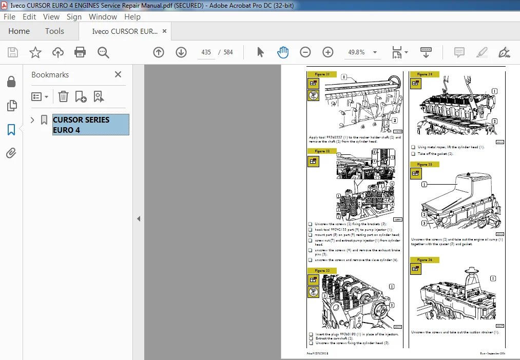
DISASSEMBLY THE ENGINE ON THE BENCH 429
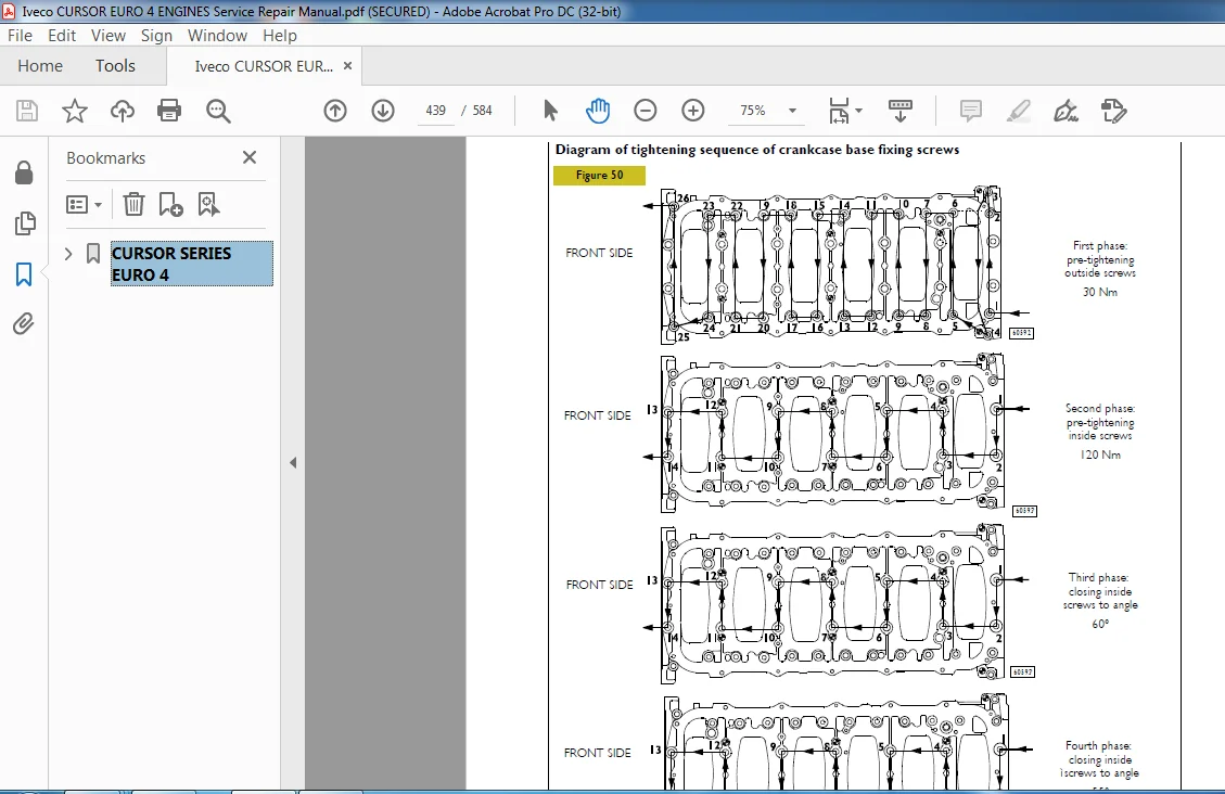
ASSEMBLING THE ENGINE ON THE BENCH 437
Diagram of tightening sequence of crankcase base fixing screws 439
Fitting connecting rod – piston assemblies in cylinder liners 440
Mounting cylinder head 441
Fitting flywheel box 442
ENGINE FLYWHEEL 443
Fitting engine flywheel 443
Fitting camshaft 444
Fitting pump-injectors 445
Fitting rocker-arm shaft assembly 445
Camshaft timing 446
Phonic wheel timing 448
Intake and exhaust rocker play adjustment and pre-loading of rockers controlling pump injectors 449
Completing Engine Assembly 450
PART TWO – ELECTRICAL EQUIPMENT 453
Components on the engine F3B 455
BLOCK DIAGRAM 456
EDC SYSTEM FUNCTIONS 457
EDC 7 UC31 electronic control unit 460
Electric injector connector ”A” 461
Sensor connector ”C” 462
Chassis connector ”B” 463
Pump injector (78247) 465
Exhaust brake solenoid valve (78050) 467
Solenoid valve for VGT control 467
Distribution pulse transmitter (48042) 468
Engine coolant temperature sensor (85153) 469
Fuel temperature sensor (47042) 470
Flywheel pulse transmitter (48035) 471
Turbine rpm sensor (48043) 472
Air pressure/temperature sensor (85156) 473
Oil temperature/pressure sensor (42030 / 47032) 473
Pre-post reheat resistor (61121) 474
PART THREE – TROUBLESHOOTING 475
PREFACE 477
DTC error codes with EDC7 UC31 central unit 479
GUIDELINE FOR TROUBLESHOOTING 501
PART FOUR – MAINTENANCE PLANNING 505
MAINTENANCE 507
Maintenance services scheme 507
MAINTENANCE INTERVALS 508
On road application 508
Off road application (quarries-construction sites) 508
Off road application (on road usage) 508
CHECKS AND/OR MAINTENANCEWORK 509
On road application 509
Off road application 509
NON-PROGRAMMED/TIMED OPERATIONS 510
On road application 510
Off road application (quarries-construction sites) 510
Off road application (on road usage) 510
SECTION 4 – General overhaul 511
GENERAL CHARACTERISTICS 513
ASSEMBLY DATA – CLEARANCE 515
REPAIRS 523
CYLINDER BLOCK 523
Checks and measurements 523
Cylinder liners 524
Removing cylinder liners 525
Assembly and checking protrusion 525
Crankshaft 526
Measuring the main journals and crankpins 527
Preliminary measurement of main and big end bearing shell selection data 528
Selecting the main bearing and big end bearing shells 529
Defining the class of diameter of themain journals and crankpins (Journals with nominal diameter) 530
Selecting the main bearing shells (Journals with nominal diameter) 531
Selecting the main bearing shells (ground journals) 532
Selecting the big end bearing shells (journals with nominal diameter) 533
Replacing the timing gear and oil pump 535
Checking main journal assembly clearance 535
Checking crankshaft end float 536
PISTON CONNECTING ROD ASSEMBLY 537
Removal 537
Measuring the diameter of the pistons 538
Conditions for correct gudgeon pin-piston coupling 538
Piston rings 539
Connecting rod 540
Connecting rods bushings 541
Checking connecting rods 541
Mounting the connecting rod — piston assembly 542
Mounting the piston rings 542
Fitting the big end bearing shells 542
Fitting connecting rod – piston assemblies in the cylinder liners 543
Checking piston protrusion 543
Checking crankpin assembly clearance 544
CYLINDER HEAD 544
Dismounting the valves 544
Checking head bearing surface on cylinder block 544
Valves 545
Valve seats 545
Checking clearance between valve-stem and associated valve guide 546
Valve guides 546
Replacing injector cases 546
Assembly 547
Checking injector protrusion 548
TIMING GEAR 549
Camshaft drive 549
Idler gear pin 549
Idler gear 549
Twin intermediate gear pin 549
Twin idler gear 549
Replacing the bushings 549
Timing system 550
Checking cam lift and pin alignment 550
Bushings 551
Valve springs 553
ROCKER SHAFT 554
Shaft 555
Rocker arms 555
REPAIR 556
Variable geometry movement control 556
Checking the actuator 557
Checking actuator travel 557
Cleaning turbine body 558
TIGHTENING TORQUE 561
Diagram of tightening sequence of crankcase base fixing screws 564
Diagram of tightening sequence of exhaust manifold fixing screws 565
Diagram of tightening sequence of exhaust manifold fixing screws 565
Diagram of tightening sequence of screws and nuts fixing turbocharger on exhaust manifold 565
SECTION 5 – Tools 569
TOOLS 571
Appendix 581
SAFETY PRESCRIPTIONS 583
PLEASE NOTE:
- This is the same manual used by the DEALERSHIPS to SERVICE your vehicle.
- The manual can be all yours – Once payment is complete, you will be taken to the download page from where you can download the manual. All in 2-5 minutes time!!
- Need any other service / repair / parts manual, please feel free to contact us at heydownloadss @gmail.com . We may surprise you with a nice offer