Iveco Daily 2000MY Repair Manual – PDF DOWNLOAD
Original price was: $49.95.$33.95Current price is: $33.95.
Iveco Daily 2000MY Repair Manual – PDF DOWNLOAD
DAILY
REPAIR MANUAL
MECHANICAL
ELECTRIC/ELECTRONIC
Description
Iveco Daily 2000MY Repair Manual – PDF DOWNLOAD
FILE DETAILS:
Iveco Daily 2000MY Repair Manual – PDF DOWNLOAD
Format: PDF
Language: English
Brand: Iveco
DESCRIPTION:
Iveco Daily 2000MY Repair Manual – PDF DOWNLOAD
DAILY
REPAIR MANUAL
MECHANICAL
ELECTRIC/ELECTRONIC
”This document provides data, characteristics, instructions and methodology to perform repair interventions on the vehicle and its components. Anyhow, this document is addressed to qualified and specialised personnel. Iveco commercial and assistance network personnel as well as all Iveco authorised points of assistance are specifically qualified and equipped to perform the repair interventions that are indicated in this document.
- Before performing any intervention, check to have available the document relating to the vehicle model on which the intervention is being performed and also make sure that all accident prevention devices, such as, as a rough guide, goggles, helmet, gloves, shoes, as well as work tooling, lifting and transport tooling, etc., are available and efficient, and further make sure that the vehicle is put such a way that an intervention can be made in safety conditions. Making interventions strictly observing the indications given here, as well as using specific tooling indicated, assures a correct repair intervention, execution timing observance and operators’ safety.
- Each repair intervention must be finalised to the recovery of functionality, efficiency and safety conditions that are provided by Iveco. Each intervention, on the vehicle, that is finalised to a modification, alteration or else, which is not authorised by Iveco, involves the exclusion of any responsibility for Iveco, and, in particular, where the vehicle is covered by a guarantee, each such intervention involves an immediate lapse of the guarantee.
- Responsibility for Iveco in repair intervention execution is excluded. Iveco is available to provide all clarifications necessary tomake interventions, as well as to provide indications in cases and situations not included in this document. Data and information contained in this document could result not to be updated owing to modifications made by Iveco at any moment for technical or commercial reasons, or because of the need to adapt the vehicle to law requirements in different countries.
- In the case of a difference between what contained here and what actually found on the vehicle, please contact Iveco network before making any intervention.” The data contained in this publication might fail to reflect the latest changes which the Manufacturer may introduce at any time, for technical or sales purposes, or to meet the requirements of local legislation. Copy, even partial, of text and drawings is forbidden.
IVECO DAILY 2000MY REPAIR MANUAL – PDF DOWNLOAD:
TABLE OF CONTENTS:
Iveco Daily 2000MY Repair Manual – PDF DOWNLOAD
DAILY 1
REPAIR MANUAL 1
MECHANICAL – ELECTRIC/ELECTRONIC 1
PRELIMINARY REMARKS 3
SYMBOLS – WARNINGS 3
SYMBOLS – ASSISTANCE OPERATIONS 4
PRODUCT CODE 5
GENERAL WARNINGS 6
GENERALWARNINGS ON THE ELECTRIC SYSTEM 8
Bonding and screening 9
OPTIONAL ELECTRICAL AND MECHANICAL PARTS INSTALLATIONS 10
CONVERSIONS BETWEEN THE MAIN UNITS OF MEASUREMENT OF THE INTERNATIONAL SYSTEM AND MOST USED DERIVED QUANTITIES 10
UPDATE DATA 11
INDEX OF SECTIONS 13
SECTION 1 – General 15
General 15
IDENTIFICATION DATA 17
Vehicle Identification Plate 17
COMPOSITION OF MODELS 18
ALPHANUMERICAL CODING FOR VEHICLE IDENTIFICATION 21
ALPHANUMERICAL CODING FOR BUS IDENTIFICATION 30
REPLENISHING FLUIDS 33
SECTION 2 – Engines 35
Engines 35
Engines 8140 XXX 37
MAIN SERVICING OPERATIONS TO BE PERFORMED ON VEHICLE ENGINE 39
ENGINE REMOVAL-REFITTING 41
Removal (Engine 8140 43B/R/S) 41
Removal (Engine 8140 43C – 8140 63) 46
Refitting 47
Checks and tests 47
Bleending the fuel system 48
Power steering system air bleed 48
OXICAT – OXYDIZER CATALYST (Vehicles with 8140 43C – 8140 63 engines) 48
Description 48
Cylinder head removal and refitting 49
Removal 49
Refitting 50
REPLACING BELTS 51
Replacing air-conditioning compres- sor drive belt 51
Disassembly 51
Assembly and adjusting belt tension 51
Replacing water pump – alternator drive belt 51
Disassembly 51
Assembly and adjusting belt tension 51
Changing the timing system driving belt 51
Disassembly 51
Removal 52
Refitting 53
REPLACINGWATER PUMP 54
Disassembly 54
Assembly 54
REPLACING INJECTORS (ENGINE 8140 63 – 8140 43C) 55
Disassembly 55
Assembly 55
REPLACING INJECTION PUMP 55
Disassembly 55
Assembly and injection pump adjustment 56
ENGINE FLYWHEEL REMOVAL-REFITTING 57
Removal 57
Refitting 57
Removal 57
Refitting 57
Engines with electronic high-pressure injection system 59
EMISSIONS VALUES 63
Engine 8140 43R 43XX/44XX 63
Engine 8140 43B 43XX/44XX 64
Engine 8140 43S 41 65
Engine 8140 43S 43XX/44XX 66
Engine 8140 43N 43XX/44XX 67
GENERAL SPECIFICATIONS 72
ASSEMBLY DATA – CLEARANCES 75
TIGHTENING TORQUES 80
TOOLS 83
OVERHAULING ENGINE 91
DISASSEMBLINGTHE ENGINEAT THE BENCH 91
REPAIR OPERATIONS 97
CYLINDER BLOCK 97
Checks and measurements 97
Checking head mating surface on cylinder block 98
Spare cylinder barrel assembling 98
CRANKSHAFT 100
Measuring main journals and connecting rods 100
Checking crankshaft 102
Replacing gearbox input shaft centering ring 103
Replacing timing control gear 103
ENGINE ASSEMBLY 103
Assembling main bearings 103
Measuring main journals assembly clearances 104
Checking crankshaft end float 105
Checking alignment pulley crankshaft 105
Rear crankshaft cover 105
Front crankshaft cover 105
ENGINE FLYWHEEL 106
Replacing bearing supporting gearbox input shaft 106
Replacing engine flywheel ring gear 106
CONNECTING ROD – PISTONAS- SEMBLY 106
Pistons 108
Measuring the pistons diameter 108
Piston gudgeon pins 108
Conditions for correct pin-piston coupling 108
Piston rings 109
Connecting rods 110
Bushes 110
Checking connecting rod for distortion 110
Checking torsion 111
Checking bending 111
Assembling connecting rod – piston assembly 111
Coupling connecting rod – pistons 111
Checking for connecting rod – piston distortion 112
Assembling piston rings 112
Assembling connecting rod – piston assemblies in cylinder barrels 112
Measuring connecting rod assembly clearance 113
Checking piston protrusion 113
Flywheel adjustment 114
CYLINDER HEADS 115
Disassembling camshaft 115
Checks 115
Checking cam lift and journal alignment 116
VALVE TAPPET 116
Disassembling valves 116
Checking cylinder head seal 117
Checking cylinder head mating surface 117
VALVES 117
Removing deposits, refacing and checking valves 117
Checking clearance between valve stem and valve guide and centring valves 118
VALVE GUIDES 118
Replacing valve guides 118
Reaming valve guides 118
VALVE SEATS 118
Regrinding and replacing valve seats 118
VALVE SPRINGS 120
ASSEMBLING CYLINDER HEADS 120
Assembling valves 120
Assembling tappets 121
Assembling camshaft 121
Adjusting tappet clearance 121
Refitting cylinder head 123
AUXILIARY MEMBER ASSEMBLY 124
Disassembling auxiliary member assembly 124
Oil pressure control valve 125
OIL PUMP 125
Assembling auxiliary member assembly 126
6-element heat exchanger 128
LUBRICATION 129
General 129
Oil vapour recycling system 129
COOLING 131
Description 131
Operation 131
Electromagnetic pulley 132
Water pump 132
Thermostat 132
TIMING AND AUXILIARY MEMBER CONTROL 133
Setting the timing system 133
Checking and aligning electromagnetic coupling pulleys 135
Checking alternator pulley alignment 136
Checking compressor pulley alignment 136
Adjusting alternator – water pump drive belt tension 136
Adjusting compressor – air-conditioner drive belt tension 136
Timing system speed sensor 139
Engine speed sensor 139
SUPERCHARGING 140
Description 140
Turbocharger 140
REPAIRS 141
PRESSURE RELIEF VALVE 141
Checking and adjusting the pressure relief valve 141
Changing the pressure relief valve 141
GARRET GT 2256 T variable geometry turbosupercharger 142
General 142
Operation at low engine rpm 142
Operation at high engine rpm 142
Proportional solenoid valve controlling turbocharger actuator 143
Actuator 143
REPAIRS 144
Checking the actuator 144
FUEL SUPPLY 145
HIGH-PRESSURE ELECTRONIC INJECTION SYSTEM (COMMON RAIL MS 6 3 OR EDC 16) 145
General 145
SYSTEM OPERATION 147
Self-diagnosis – BLINK CODE 147
Immobilizer recognition 147
Checking fuel temperature 147
Checking engine coolant temperature 147
Checking quantity of fuel injected 147
Checking idling adjustment 147
Fuel cut-off in release phase 147
Checking cylinder balancing on idling 147
Checking regulator engine rotation (anti-sawing) 147
Checking smokiness at exhaust on acceleration 147
Checking exhaust gas recirculation (E G R if present) 147
Checking top speed limit 147
Checking rotation regularity during acceleration 147
Checking thermostart 147
Checking activation of air-conditioning system 147
Checking fuel pump 147
Checking diesel warming 148
Checking cylinder position 148
Checking pilot and main injection timing 148
Checking injection pressure closed cycle 148
Fuel supply 148
Correcting flow rate according to water temperature 148
Correcting flow rate to avoid noise, smoke or overloading 148
De-rating 148
Adjusting turbine speed (for variable geometry turbocharger – when present) 148
Injection timing electronic test 148
Speed governor 148
Engine starting 148
Cold starting 149
Warm starting 149
Run up 149
After run 149
Cut-off 149
Cylinder balancing 149
Synchronization search 149
Operation 150
HYDRAULIC SYSTEM 151
Fuel pump 151
Specifications 151
Fuel filter 152
Tightening torques 152
Fuel pipes 152
High-pressure pump 153
3rd pumping element exclusion device 154
Pressure regulator 154
Hydraulic accumulator (rail) 155
Flow limiters 155
Pressure relief valve 157
Fuel recirculation and supply system 157
ELECTRO-INJECTORS 159
Operation 159
ELECTRIC/ELECTRONIC COMPONENTS 160
Electronic control unit MS6 3 or EDC 16 160
SENSORS 160
Engine speed sensor 160
Camshaft timing sensor 160
Air temperature and pressure sensor 160
Fuel temperature sensor 160
Fuel pressure sensor 161
Atmospheric pressure sensor 161
Engine coolant temperature sensor 161
Throttle pedal position sensor 161
Clutch pedal position sensor 161
Brake pedal position sensor 161
Vehicle speed sensor 161
ACTUATORS 161
PWM (PulseWidth Modulation) controls 161
EXHAUST GAS RECIRCULATION SYSTEM E G R (vehicles with homologation MI) 162
GUIDE TO TROUBLESHOOTING 163
Engines with rotary mechanical injection pump 243
TROUBLESHOOTING 245
Engine 8140 43C 43XX 255
Gas emissions 257
Smokiness 257
Noise emissions 257
GENERAL SPECIFICATIONS 260
ASSEMBLY DATA – CLEARANCES 263
TIGHTENING TORQUE 268
TOOLS 269
ENGINE OVERHAUL 270
Dismantling engine on bench 270
CYLINDER HEAD 271
Engine assembling at the bench 271
Setting the timing system 271
Injection pump assembling and timing 272
COOLING 273
Feeding 275
INJECTION PUMP TEST VALUES 277
COLD INJECTION ADVANCE AUTOMATIC DEVICE (KSB) [KALT START BETRIEBSEINRICHTUNG] 281
Description 281
Operation 281
Engine 8140 63 40XX 283
EMISSIONS VALUES 285
Gas emissions 285
Smokiness 285
Noise emissions 285
GENERAL SPECIFICATIONS 286
ASSEMBLY DATA – CLEARANCES 289
TIGHTENING TORQUES 295
TOOLS 296
8140 63 ENGINE OVERHAUL 299
Disassembly engine on bench 299
PISTONS – PINS – SNAP RINGS 302
Assembling connecting rod-piston assembly 303
Fitting connecting rods-pistons 303
CYLINDER HEADS 303
CAMSHAFT 303
Checking cam lift and journal alignment 303
Checking cylinder head mating surface 304
PRECOMBUSTION CHAMBERS 305
Disassembly 305
Assembly 305
GLOW PLUGS 306
Disassembly 306
Checking glow plugs continuity 306
Assembly 306
LUBRICATION 306
Heat exchanger 306
Oil vapour full recirculation system (Blow-by) 307
COOLING SYSTEM 308
Thermostat 308
EXHAUST GAS RECIRCULATION SYSTEM E G R 309
General Information 309
Operation 309
Modulating solenoid valve 311
Potentiometer on injection pump lever 311
Engine rpm sensor 311
Engine coolant temperature sensor 312
Absolute pressure sensor 312
Vacuum sensor 312
Electronic control unit 312
OPERATION LOGICS 313
Air conditioner interface operation logic 313
Pre-Post Heating Operating Logic 313
Engine Cooling Fan Operating Logic 313
KSB Operating Logic 313
Feeding 315
INJECTION PUMP TEST VALUES 317
F1A engine 321
MAIN OPERATIONS ON ENGINE MOUNTED ON VEHICLE 325
ENGINE REMOVAL-REFITTING 327
Removal 327
Refitting 331
Checks and tests 331
Power steering system air bleed 331
REPLACING BELTS 332
Replacing air-conditioning compressor drive belt (version with belt tensioner) 332
Disassembly 332
Assembly and adjusting belt tension 332
Replacing air-conditioning compressor drive belt (version with elastic belt) 332
Disassembly 332
Assembly 332
Power steering pump-alternator belt replacement 332
Disassembly 332
Assembly 332
Replacing timing drive belt 333
Disassembly 333
Assembly 334
REPLACING ELECTRO-INJECTORS 335
Disassembly 335
Assembly 335
CYLINDER HEAD REMOVAL AND REFITTING 336
Removal 336
Refitting 338
REPLACING HIGH-PRESSURE PUMP CP3 339
Removal 339
Refitting 339
REPLACINGWATER PUMP 339
Removal 339
Refitting 339
EMISSIONS 340
ENGINE IDENTIFICATION CODE 342
GENERAL SPECIFICATIONS 344
ASSEMBLY DATA – CLEARANCES 347
TOOLS 352
EXPERIMENTAL TOOLS 357
TIGHTENING TORQUE 368
OVERHAULING ENGINE F1A 373
DISASSEMBLING THE ENGINE AT THE BENCH 373
REPAIRS 382
CYLINDER BLOCK 382
Checks and measurements 382
Checking head mating surface on cylinder block 383
CRANKSHAFT 383
Measuring main journals and crank pins 383
Checking crankshaft 384
Replacing timing control gear 386
ENGINE ASSEMBLY 386
Assembling main bearings 386
Measuring main journal assembly clearance 386
Checking crankshaft end float 387
Assembling rear seal 388
ENGINE FLYWHEEL 389
Replacing bearing supporting gear- box input shaft 389
CONNECTING ROD – PISTON ASSEMBLY 389
Pistons 390
Measuring piston diameter 390
Piston pins 391
Conditions for correct pin-piston coupling 391
Piston rings 391
Connecting rods 392
Bushes 393
Checking connecting rods 393
Checking torsion 393
Checking bending 393
Assembling connecting rod-piston assembly 393
Checking for connecting rod – piston distortion 394
Assembling piston rings 394
Assembling connecting rod – piston assemblies in cylinder barrels 394
Measuring crankpin assembly clearance 395
Checking piston protrusion 395
CYLINDER HEAD 396
Disassembly 396
Removing valves 396
Checking cylinder head seal 397
Checking cylinder head mating surface 397
VALVES 397
Removing deposits, refacing and checking valves 397
Checking clearance between valve stem and valve guide and centring valves 398
VALVE GUIDES 398
Replacing valve guides 398
Boring valve guides 398
VALVE SEATS 399
Regrinding – replacing valve seats 399
VALVE SPRINGS 400
ROCKER ARMS – TAPPETS 400
Checks 401
ASSEMBLING CYLINDER HEADS 401
Overhead 402
Overhead removal 402
TIMING SYSTEM 403
Description 403
Camshaft 404
Checks 404
Checking cam lift and pin alignment 404
Assembling overhead 405
Assembling front seal ring 406
Refitting cylinder head 409
Adjusting air-conditioner – compressor drive belt tension 412
Timing speed sensor 416
Engine speed sensor 416
LUBRICATION 417
General 417
OIL VACUUM PUMP ASSEMBLY (GPOD) 419
Oil pump 419
Characteristic data 419
Vacuum pump 419
Oil pressure control valve 420
Oil filter 420
Modine heat exchanger 420
Oil vapour recirculation system 421
Description 421
COOLING 422
Description 422
Operation 422
Electromagnetic pulley 423
Water pump 423
Thermostat 423
TURBOCHARGING 424
Description 424
Turbocharger 425
REPAIRS 426
Pressure relief valve 426
Checking and adjusting pressure relief valve 426
Replacing pressure relief valve 426
EXHAUST GAS RECIRCULATION (EGR) SYSTEM 427
EGR system operation 427
Operating principles 427
Air flow meter 428
FUEL SUPPLY 429
HIGH-PRESSURE ELECTRONIC INJECTION SYSTEM (MS 6 3 – EDC 16) 429
General 429
SYSTEM OPERATION 431
Self-diagnosis – BLINK CODE 431
Immobilizer recognition 431
Checking fuel temperature 431
Checking engine coolant temperature 431
Checking quantity of fuel injected 431
Checking idling adjustment 431
Fuel cut-off in release phase 431
Checking cylinder balancing on idling 431
Checking regular engine rotation (anti-sawing) 431
Checking smokiness at exhaust on acceleration 431
Checking exhaust gas recirculation (E G R if present) 431
Checking top speed limit 431
Checking regular rotation on acceleration 431
Checking glow plug control unit 431
Checking activation of air-conditioning system 431
Checking fuel pump 431
Checking diesel warming 432
Checking cylinder position 432
Checking pilot and main injection timing 432
Checking injection pressure closed cycle 432
Fuel supply 432
Correcting flow rate according to water temperature 432
Correcting flow rate to avoid noise, smoke or overloading 432
De-rating 432
Injection timing electronic test 432
Speed governor 432
Engine starting 432
Cold starting 433
Warm starting 433
Run up 433
After run 433
Cut-off 433
Cylinder balancing 433
Synchronization search 433
OPERATION 435
HYDRAULIC SYSTEM 437
Fuel pump 437
Specifications 437
Fuel filter 438
Tightening torques 438
Fuel pipes 438
High-pressure pump 439
High-pressure pump internal structure 441
Working principle 442
Pressure control valve 445
Replacing pressure regulator 445
MECHANICAL SUPPLY PUMP 446
Hydraulic accumulator (rail) 447
Overpressure valve (for forged hydraulic accumulator) 447
ELECTRO-INJECTORS 447
Operation 448
ELECTRIC/ELECTRONIC COMPONENTS 448
Electronic control unit MS6 3 or EDC 16 448
Glow plug electronic control unit 449
Glow plugs 449
SENSORS 449
Engine speed sensor 449
Camshaft timing sensor 449
Air temperature and pressure sensor 449
Fuel temperature sensor 449
Fuel pressure sensor 449
Atmospheric pressure sensor 449
Engine coolant temperature sensor 450
Throttle pedal position sensor 450
Clutch pedal position sensor 450
Brake pedal position sensor 450
Vehicle speed sensor 450
ACTUATORS 450
PWM (PulseWidth Modulation) controls 450
GUIDE TO TROUBLESHOOTING 451
F1C engine 523
ENGINE VIEWS 527
ENGINE IDENTIFICATION CODE 530
CHARACTERISTIC CURVES 534
GENERAL SPECIFICATIONS 536
ASSEMBLY DATA – CLEARANCES 539
TOOLS 544
EXPERIMENTAL TOOLS 550
TIGHTENING TORQUE 557
OVERHAULING ENGINE F1C 560
DISASSEMBLING THE ENGINE AT THE BENCH 560
REPAIRS 570
CYLINDER BLOCK 570
Checks and measurements 570
Checking head mating surface on cylinder block 571
CRANKSHAFT 571
Measuring main journals and crank pins 571
Checking crankshaft 572
Replacing timing control gear 574
ENGINE ASSEMBLY 574
Assembling main bearings 574
Measuring main journal assembly clearance 574
Checking crankshaft end float 575
Assembling rear seal 576
ENGINE FLYWHEEL 577
CONNECTING ROD – PISTON ASSEMBLY 577
Pistons 578
Measuring piston diameter 578
Piston pins 579
Conditions for correct pin-piston coupling 579
Piston rings 579
Connecting rods 580
Bushing 580
Checking connecting rods 580
Checking torsion 581
Checking bending 581
Assembling connecting rod-piston assembly 581
Checking for connecting rod – piston distortion 582
Assembling piston rings 582
Assembling connecting rod – piston assemblies in cylinder barrels 582
Measuring crankpin assembly clearance 582
Checking piston protrusion 583
CYLINDER HEAD 584
Disassembly 584
Disassembling valves 584
Checking cylinder head seal 585
Checking cylinder head mating surface 585
VALVES 585
Removing deposits, refacing and checking valves 585
Checking clearance between valve stem and valve guide and centring valves 586
VALVE GUIDES 586
Replacing valve guides 586
Boring valve guides 586
VALVE SEATS 587
Regrinding – replacing valve seats 587
VALVE SPRINGS 588
ROCKER ARMS – TAPPETS 588
Checks 589
ASSEMBLING CYLINDER HEADS 589
Overhead 590
Overhead removal 590
TIMING SYSTEM 591
Description 591
Camshaft 592
Checks 592
Checking cam lift and pin alignment 592
Assembling overhead 593
AUXILIARY ORGAN CONTROLS 593
Cylinder head refitting 595
TIMING SYSTEM CONTROL 596
Replacement of alternator free wheel 601
Timing speed sensor 606
Engine speed sensor 606
LUBRICATION 607
General 607
OIL PUMP/DEPRESSOR UNIT 609
Oil pump 609
Characteristic data 609
Vacuum pump 610
Oil pressure adjusting valve 610
Disassembly 610
Assembly 611
Oil filter 611
Heat exchanger 611
Disassembly 611
Assembly 611
Oil vapour recirculation (Blow-by) 613
Operation 613
COOLING 614
Description 614
Operation 614
Electromagnetic pulley 615
Water pump 615
Thermostat 615
TURBOCHARGING 616
Description 616
Turbocharger type MITSUBISHI TD 4 HL-13T – 6 617
REPAIRS 618
Pressure relief valve 618
Checking and adjusting pressure relief valve 618
Changing the pressure relief valve 618
GARRET GT 2256 T variable geometry turbosupercharger 619
General 619
Operation at low engine rpm 619
Operation at high engine rpm 619
Proportional solenoid valve controlling turbocharger actuator 620
Actuator 620
REPAIRS 621
Checking and adjusting the actuator 621
FUEL SUPPLY 623
HIGH-PRESSURE ELECTRONIC INJECTION SYSTEM (EDC 16) 623
General 623
SYSTEM OPERATION 625
Self-diagnosis – BLINK CODE 625
Immobilizer recognition 625
Checking fuel temperature 625
Checking engine coolant temperature 625
Checking quantity of fuel injected 625
Checking idling adjustment 625
Fuel cut-off in release phase 625
Checking cylinder balancing on idling 625
Checking regular engine rotation (anti-sawing) 625
Checking smokiness at exhaust on acceleration 625
Checking exhaust gas recirculation (E G R if present) 625
Checking top speed limit 625
Checking regular rotation on acceleration 625
Checking glow plug control unit 625
Checking activation of air-conditioning system 625
Checking fuel pump 625
Checking diesel warming 626
Checking cylinder position 626
Checking pilot and main injection timing 626
Checking injection pressure closed cycle 626
Fuel supply 626
Correcting flow rate according to water temperature 626
Correcting flow rate to avoid noise, smoke or overloading 626
De-rating 626
Injection timing electronic test 626
Speed governor 626
Engine starting 626
Cold starting 627
Warm starting 627
Run up 627
After run 627
Cut-off 627
Cylinder balancing 627
Synchronization search 627
OPERATION 629
HYDRAULIC SYSTEM 629
Fuel pipes 629
Fuel pump 630
Specifications 630
Fuel filter 631
Tightening torques 631
High-pressure pump 632
High-pressure pump internal structure 634
Working principle 635
Pressure control valve 638
MECHANICAL SUPPLY PUMP 638
Hydraulic accumulator (rail) 639
ELECTRO-INJECTORS 639
Operation 639
ELECTRIC/ELECTRONIC COMPONENTS 640
Electronic control unit EDC 16 640
Glow plug electronic control unit 640
Glow plugs 640
SENSORS 640
Engine speed sensor 640
Camshaft timing sensor 640
Air temperature and pressure sensor 641
Fuel temperature sensor 641
Fuel pressure sensor 641
Atmospheric pressure sensor 641
Engine coolant temperature sensor 641
Throttle pedal position sensor 641
Clutch pedal position sensor 641
Brake pedal position sensor 641
Vehicle speed sensor 641
ACTUATORS 641
PWM (PulseWidth Modulation) controls 641
SECTION 3 – Clutch 643
Clutch 643
DESCRIPTION 645
DIAGNOSTICS 646
CHARACTERISTICS AND DATA 649
TIGHTENING TORQUES 657
TOOLS 657
CLUTCH REMOVAL AND REFITTING 658
Removal 658
CHECKS 658
Refitting 659
THRUST BEARING REMOVAL AND REFITTING 659
HYDRAULIC CLUTCH DRIVE 660
HYDRAULIC CLUTCH DRIVE REMOVAL – REFITTING 662
Removal 662
Refitting 662
PEDAL BOARD REMOVAL – REFITTING 664
Removal 664
Refitting 664
PEDAL BOARD 665
SECTION 4 – Transmission 667
Transmission 667
DIAGNOSTICS 669
TRANSMISSION REMOVAL – REFITTING 673
Removal 673
Refitting 673
GEAR CONTROL 674
5 S 200 – 5 S 270 Transmissions 675
GENERAL 677
GEAR SELECTION AND ENGAGEMENT CONTROL 678
SAFETY DEVICES 679
Engagement locking device 679
Reverse gear anti-engagement device 679
SPECIFICATIONS AND DATA 680
TIGHTENING TORQUES 682
TOOLS 683
OVERHAULING THE TRANSMISSION 689
Gear control box 689
Disassembly 689
Assembly 689
Disassembling the transmission 691
Disassembling the rear cover bearings 693
Disassembling the transmission bearings 693
Disassembling the main shaft 694
Drive input shaft 696
Disassembling the transmission shaft 696
CHECKS 699
Transmission 699
Hubs – sliding sleeves – forks 699
Bearings 699
Shafts – gears 0 35 699
Synchronizing devices 699
Mounting the transmission shaft 700
Mounting the main shaft 700
Rods – forks – selector – driver 703
Disassembly – assembly 703
Mounting the transmission 703
Adjusting the transmission shaft bearing end float 703
6 S 300 Transmission 709
GENERAL 711
GEAR SELECTION AND ENGAGEMENT 712
SPECIFICATIONS AND DATA 714
TIGHTENING TORQUES 716
TOOLS 717
OVERHAULING THE TRANSMISSION 725
Gear control box 725
Disassembly 725
Assembly 725
Check levers mounting 726
Disassembling the transmission 727
Disassembling the rear cover bearings 730
Disassembling the transmission bearings 730
Disassembling the main shaft 731
Disassembling the drive input shaft 732
Disassembling the transmission shaft 732
CHECKS 737
Transmission 737
Hubs – sliding sleeves – forks 737
Bearings 737
Shafts – gears 737
Synchronizing devices 737
Mounting the transmission shaft 739
Mounting the main shaft 740
Rods – forks – selector – driver 743
Disassembly – assembly 743
Mounting the transmission 743
Adjusting the transmission shaft bearing end float 743
6 S 380 O D Transmission 749
GENERAL 751
GEAR SELECTION AND ENGAGEMENT 752
SPECIFICATIONS AND DATA 754
TIGHTENING TORQUES 756
TOOLS 757
OVERHAULING THE TRANSMISSION 765
Gear control box 765
Disassembly 765
Assembly 765
Check levers mounting 766
Disassembling the transmission 767
Disassembling the rear cover bearings 770
Disassembling the transmission bearings 771
Disassembling the main shaft 771
Disassembling the drive input shaft 773
Disassembling the transmission shaft 773
CHECKS 777
Transmission 777
Hubs – sliding sleeves – forks 777
Bearings 777
Shafts – gears 777
Synchronizing devices 777
Mounting the transmission shaft 779
Mounting the main shaft 780
Rods – forks – selector – driver 783
Disassembly – assembly 783
Mounting the transmission 783
Adjusting the transmission shaft bearing end float 783
Power take off 789
SPECIFICATIONS AND DATA 791
TIGHTENING TORQUES 792
ASSEMBLY STANDARDS 793
POWER TAKE OFF ELECTRIC ACTUATOR 794
Description 794
Operation 794
SECTION 5 – Propeller shafts 797
Propeller shafts 797
SPECIFICATIONS AND DATA 799
DIAGNOSTICS 805
TIGHTENING TORQUES 806
TOOLS 806
PROPELLER SHAFT REMOVAL AND REFITTING 807
Removal 807
Refitting 807
CHECKING PROPELLER SHAFTS ON VEHICLE 807
SECTION 6 – Rear axles 809
Rear axles 809
DIAGNOSTICS 811
Rear axle 450210 813
REAR AXLE REMOVAL – REFITTING 815
Removal 815
Refitting 815
DESCRIPTION 817
SPECIFICATIONS AND DATA 818
TIGHTENING TORQUES 820
TOOLS 823
OVERHAULING THE REAR AXLE ASSEMBLY 827
Air breather disassembly – assembly 827
Wheel hub overhaul 827
Assembly 828
REPAIRING THE DIFFERENTIAL 830
Disassembling the differential unit 830
Gear housing removal 831
Checking the parts comprising the differential 833
Assembly 833
Assembly of gear housing 834
Assembling the bevel pinion assembly 835
Assembly of differential unit 838
Rear axles 450311/1 450511 843
REAR AXLE REMOVAL – REFITTING 845
Removal 845
Refitting 845
DESCRIPTION 847
SPECIFICATIONS AND DATA 848
TIGHTENING TORQUES 851
TOOLS 853
OVERHAULING THE REAR AXLE ASSEMBLY 856
Wheel hub overhaul 856
Replacing the wheel hub bearing 857
DIFFERENTIAL REPAIR OPERATIONS 860
Disassembly of differential locking 860
Differential locking removal 860
Assembling the differential locking device 860
Differential locking refitting 860
Adjusting the differential locking device 861
Disassembling the differential unit 861
Disassembly of gear housing 862
Assembly of gear housing 864
Differential unit refitting 865
Rear axle 450517/2 869
REAR AXLE REMOVAL – REFITTING 871
Removal 871
Refitting 871
DESCRIPTION 873
SPECIFICATIONS AND DATA 874
TIGHTENING TORQUES 876
TOOLS 878
OVERHAULING THE REAR AXLE ASSEMBLY 882
Air breather disassembly – assembly 882
Overhaul of wheel hubs 882
Removal 882
Stud replacement 884
Refitting 884
Refitting 885
DIFFERENTIAL REPAIR OPERATIONS 887
Differential locking 887
DIFFERENTIAL REPAIR OPERATIONS 888
Differential unit removal 888
Gearing case removal 888
Differential components check 890
Rear axle casing check 890
Gearing case refitting 890
Differential unit refitting 894
SECTION 7 – Axles 899
Axles 899
DIAGNOSTICS 901
Axle 5817 905
DESCRIPTION 907
SPECIFICATIONS AND DATA 908
TIGHTENING TORQUES 909
TOOLS 910
REMOVING AND REFITTING AXLE 5817 911
Removal 911
Refitting 911
REPAIRS 913
OVERHAULING AXLE 5817 913
Wheel hub removal and refitting 913
Removal 913
Replacing phonic wheel 914
Refitting 914
STUB AXLE REMOVAL-REFITTING 915
Removal 915
Refitting 917
Axle 5818 919
DESCRIPTION 921
SPECIFICATION AND DATA 921
TIGHTENING TORQUES 922
TOOLS 923
OVERHAULING AXLE 5818 924
Replacing phonic wheel 924
Refitting 925
Axle 5819 927
DESCRIPTION 929
SPECIFICATION AND DATA 930
TIGHTENING TORQUES 931
TOOLS 932
REPAIR OPERATIONS 934
AXLE 5819 OVERHAUL 934
Stub axle removal and refitting 934
Removal 934
Refitting 934
Axle 5823 935
DESCRIPTION 937
SPECIFICATION AND DATA 938
TIGHTENING TORQUES 939
TOOLS 940
REMOVING AND REFITTING AXLE 5823 941
Removal 941
Refitting 942
AXLE 5823 OVERHAUL 943
Wheel hub removal and refitting 943
Removal 943
Replacing phonic wheel 944
Re-fitting 944
Wheel geometry 947
DESCRIPTION 949
WHEEL GEOMETRY 951
SPECIFICATIONS AND DATA 951
TIGHTENING TORQUES 951
TOOLS 952
CHECKING CHARACTERISTIC ANGLES 953
Positioning jaws and projectors 953
Electronic balancing of rim eccentricity 954
Wheel alignment 954
Checking toe-in 955
Front wheel deviation test (vehicle wheelbase check) 955
Checking camber 956
Checking king-pin angle and caster angle 956
Checking steering angles 957
Checking rear axle alignment 957
Calculating thickness of spacers to be fitted between tie rod mountings and chassis side members (with the exception of vehicles equipped with 5-mm thick chassis or with transverse leaf-spring suspension) 958
SECTION 8 – Suspensions 959
Suspensions 959
Front and rear mechanical suspensions 961
DIAGNOSTICS 963
Front mechanical suspensions 967
DESCRIPTION 969
ARTICULATED QUADRILATERAL SUSPENSION WITH TRANSVERSE LEAF SPRING 969
SPECIFICATIONS AND DATA 970
Front leaf spring 970
Front suspension stabilizer bar (axle 5817) 971
Front shock absorbers 972
TOOLS 972
VEHICLE SUSPENSIONS 29 L – 35 S WITHOUT SWAY BAR 973
Shock absorber data 973
TIGHTENING TORQUES 974
Vehicles 29 L – 35 S (without sway bar) 974
TIGHTENING TORQUES 975
Vehicles 29 L – 35 S 975
TIGHTENING TORQUES 976
Vehicles 35 C 976
TIGHTENING TORQUES 977
Vehicles 29 L – 35 S – 35C 977
REPAIRS 978
Check the clearance of upper swinging arm articulated 978
Check the clearance of lower swinging arm articulated head 979
OVERHAULING THE SUSPENSION 979
Suspension arms 979
Removal 979
Replacing suspension arm bushings Disassembly 979
Disassembly 979
Assembly 980
Refitting 980
STABILIZER BAR 981
Removal 981
Refitting 981
FRONT SHOCK ABSORBERS 981
Removal 981
Refitting 981
LEAF SPRING 983
Removal 983
Refitting 984
TORSION BAR SUSPENSION 985
(Axle 5819 – vehicles 35C – 40C – 45C – 50C) 985
Description 985
SPECIFICATIONS AND DATA 986
Front shock absorbers 986
Stabilizer bar diameter 986
TOOLS 987
TIGHTENING TORQUES 989
Vehicles 35 C – 40 C – 45 C – 50 C 989
REPAIRS 991
Check the clearance of upper swinging arm articulated head 991
Check the clearance of lower swinging arm articulated head 992
OVERHAULING THE SUSPENSION 993
TIE RODS 993
Removal 993
Replacing swivel heads 993
Refitting 994
TORSION BARS 994
Removal 994
Replacing silentbloc and limit stops 995
Replacing link pins 995
Refitting 996
Adjusting torsion bar pre-load 998
STABILIZER BAR 999
Removal 999
Refitting 999
FRONT SHOCK ABSORBERS 999
Removal 999
Refitting 999
TORSION BAR SUSPENSION 1001
(Axle 5823 – vehicles 60C – 65C) 1001
Description 1001
SPECIFICATIONS AND DATA 1002
Front shock absorbers 1002
Stabilizer bar 1002
TIGHTENING TORQUES 1003
EQUIPMENT 1005
REPAIR OPERATIONS 1006
SUSPENSION OVERHAUL 1006
Lower tie rod articulated heads replacement 1006
TORSION BARS 1006
Removal 1006
Rubber bush replacement 1007
Removal 1007
Refitting 1007
Torsion bar preload adjustment 1010
Rear mechanical suspensions 1011
DESCRIPTION 1013
CHARACTERISTICS AND DATA 1014
Rear leaf spring 1014
Rear shock absorbers 1031
TOOLS 1032
TIGHTENING TORQUES 1033
Vehicles 29 L – 35 S 1033
Vehicles 35 C – 40 C – 45 C- 50 C 1034
Vehicles 60C – 65C 1035
REAR LEAF SPRING 1036
Vehicles: 29 L – 35 S 1036
Removal 1036
Refitting 1036
Vehicles: 35 C – 40 C – 45 C – 50 C – 60 C – 65 C 1037
Removal 1037
Refitting 1037
REPAIRS 1038
Disassembling the leaf spring 1038
Checks 1038
Assembling the leaf spring 1038
Replacing the bushings 1038
REAR SHOCK ABSORBERS 1039
Removal 1039
Refitting 1039
STABILIZER BAR 1040
Removal 1040
Refitting 1040
Rear air suspensions 1041
DIAGNOSTIC 1043
REAR PNEUMATIC SUSPENSIONS – VB-TECHNIEK TYPE 1044
Blink – code 1044
REAR PNEUMATIC SUSPENSIONS -WABCO TYPE 1044
Blink-code 1044
Failure code table 1045
GENERAL 1046
PNEUMATIC SUSPENSIONS -WABCO TYPE (for 29L – 35S vehicles) 1046
SPECIFICATIONS AND DATA 1047
Air system components 1047
Rear leaf spring 1048
Rear shock absorbers 1048
Stabilizer bar 1048
Levelling and height values 1048
ELECTRIC SYSTEM WABCO (ECAS) 1049
PNEUMATIC SYSTEMWABCO (ECAS) 1050
PNEUMATIC SYSTEM ON VEHICLE 1051
Vehicles without ABS 1051
Vehicles with ABS 1052
CHASSIS SELF-LEVELLING, LIFTING AND LOWERING 1053
Operation 1053
MAIN SYSTEM COMPONENTS 1053
PNEUMATIC SUPPLY UNIT 1053
Specifications and data 1053
ELECTRONICCONTROLUNIT 1053
ECU programming/setting 1054
LEVEL SENSOR 1054
Level sensor replacement 1054
Removal 1054
Refitting 1054
Level sensor adjustment 1054
AIR SPRING 1055
Air spring replacement 1055
Removal 1055
Refitting 1055
LOAD SENSING VALVE 1055
Load sensing valve replacement 1056
Removal 1056
Refitting 1056
Load sensing valve adjustment on vehicle ! 1056
REAR SUSPENSION OVERHAUL 1057
LEAF SPRING 1057
Removal 1057
Refitting 1057
REAR SHOCK ABSORBERS 1057
Removal 1057
Refitting 1057
REAR STABILIZER BAR 1057
Removal 1057
Refitting 1057
PANHARD REACTION BAR 1058
Removal 1058
Refitting 1058
AIR SUSPENSIONS TYPE VB-TECHNIEK (for vehicles 35C – 40C – 45C – 50C – 60C – 65C) 1059
GENERAL INFORMATION 1059
SPECIFICATIONS AND DATA 1060
Pneumatic system (for vehicles 35 C – 50 C) 1060
Rear leaf spring (vehicles 35 C – 40 C) 1060
Rear leaf spring (vehicles 45 C – 50 C) 1061
Rear shock absorbers 1061
Levelling and height values 1061
VB TECHNIEK ELECTRIC SYSTEM 1062
PNEUMATIC SYSTEM 1063
VB-TECHNIEK ELECTRICAL SYSTEM (60 C – 65 C VEHICLES) 1064
PNEUMATIC SYSTEM (vehicles: 60 C – 65 C) 1065
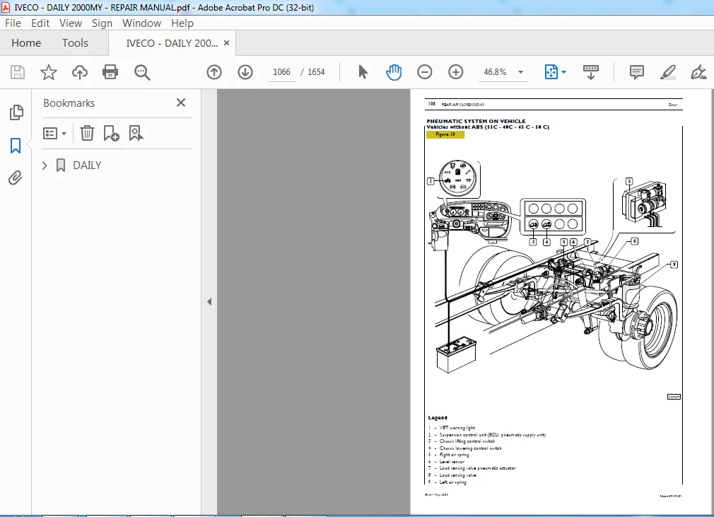
PNEUMATIC SYSTEM ON VEHICLE 1066
Vehicles without ABS (35C – 40C – 45 C – 50 C) 1066
Vehicles with ABS (35C – 40C – 45 C – 50 C) 1067
60 C – 65 C vehicles without ABS 1068
60 C – 65 C vehicles with ABS 1069
CHASSIS SELF-LEVELLING, LIFTING AND LOWERING 1070
Operation 1070
MAIN SYSTEM COMPONENTS 1070
ELECTROCOMPRESSOR 1070
ELECTRONICCONTROLUNIT 1070
ECU programming/setting 1070
LEVEL SENSOR 1071
Level sensor replacement 1071
Refitting 1071
Level sensor adjustment 1071
Removal 1071
AIR SPRING 1071
Air spring replacement 1072
Removal 1072
Refitting 1072
LOAD SENSING VALVE 1072
Load sensing valve replacement 1072
Refitting 1072
Removal 1072
Load sensing valve adjustment on vehicle 1072
REAR SUSPENSION OVERHAUL (vehicles 30 C – 35C – 40C – 45 C) 1073
LEAF SPRING 1073
Removal 1073
Refitting 1073
REAR SHOCK ABSORBERS 1074
Removal 1074
Refitting 1074
PANHARD REACTION BAR 1074
Removal 1074
Refitting 1074
REAR STABILIZER BAR 1074
Removal 1074
Refitting 1074
SECTION 9 – Wheel and Tyres 1075
Wheel and Tyres 1075
DESCRIPTION 1077
Tyre pressure 1078
TOOLS 1079
DIAGNOSTICS 1079
STATIC WHEEL BALANCING 1082
TYRE PRESSURE 1083
HOW TYRE BEHAVIOUR DEPENDS ON PRESSURE 1083
SECTION 10 – Steering gear 1085
Steering gear 1085
STEERING GEAR 1087
General 1087
POWER STEERING SPECIFICATIONS AND DATA 1088
Steering gear 1088
TIGHTENING TORQUES 1089
SPECIFIC TOOLS 1089
DIAGNOSTICS 1090
POWER STEERING 1095
Description 1095
POWER STEERING TYPE TRW 1096
Operation 1096
POWER STEERING TYPE ZF 1098
Operation 1098
CHECKS AND OPERATIONS ON THE VEHICLE 1100
Checking maximum pressure 1100
Checking hydraulic steering centre (for ”ZF” power steering only) 1100
Bleeding the air from the hydraulic system 1100
SWIVEL HEADS 1100
PROTECTION CASINGS 1100
STEERING GEAR CONTROL 1100
Vehicles equipped with an Air-Bag 1100
SAFETY STANDARDS TO BE OBSERVED DURING REPAIR OR MAINTENANCE OPERATIONS ON VEHICLES EQUIPPED WITH AIR-BAG SYSTEM PROVIDED BY SUPPLIER 1101
Preliminary Standards 1101
Repairs and inspections required after an accident 1101
Accidents with or without Air-Bag module activation 1101
Accidents with or without Air-Bag module activation 1101
Painting 1102
Risks for health 1102
Overexposure effects 1102
Safety Standards to observe when handling Air-Bag modules 1102
Air-Bag module scrapping 1103
Safety Standards to observe when handling pretensioners 1103
Pretensioners scrapping 1104
Operations on system components 1104
Removing and scrapping activated Air-Bag module and pretensioner from vehicle 1104
Removing and scrapping non-activated Air-Bag module from a repairable vehicle 1104
Air-Bag module deployment Remote activation 1105
Activating Air-Bag modules and electronic pretensioners installed on unrecoverable vehicles 1105
Upper steering gear shaft removal 1107
For vehicles equipped with Air-Bag 1107
For all vehicles 1107
Refitting 1108
Lower steering gear shaft removal 1108
Refitting 1109
HYDRAULIC POWER STEERING 1109
Hydraulic power steering removal 1109
Refitting 1109
Steering linkage replacement 1110
Removal 1110
Refitting 1110
Rubber bushing replacement procedure 1110
POWER STEERING PUMP 1111
Power steering pump overhaul procedure 1112
SECTION 11 – Hydro-pneumatic system – Brakes 1113
Hydro-pneumatic system – Brakes 1113
GRAPHIC SYMBOLS FOR AIR/HYDRAULIC SYSTEM CIRCUIT DIAGRAMS (MISCELLANEOUS AND GENERATORS) 1115
GRAPHIC SYMBOLS FOR AIR/HYDRAULIC SYSTEM CIRCUIT DIAGRAMS (VALVES) 1116
GRAPHIC SYMBOLS FOR AIR/HYDRAULIC SYSTEM CIRCUIT DIAGRAMS (TANKS AND ACCUMULATORS) 1122
GRAPHIC SYMBOLS FOR AIR/HYDRAULIC SYSTEM CIRCUIT DIAGRAMS (CONVERTERS, CYLINDERS AND CALIPERS) 1123
GRAPHIC SYMBOLS FOR AIR/HYDRAULIC SYSTEM CIRCUIT DIAGRAMS (CALIPERS AND CYLINDERS) 1124
GRAPHIC SYMBOLS FOR AIR/HYDRAULIC SYSTEM CIRCUIT DIAGRAMS (SEMI-COUPLINGS AND COUPLING HEADS) 1125
GRAPHIC SYMBOLS FOR AIR/HYDRAULIC SYSTEM CIRCUIT DIAGRAMS (INDICATORS AND SWITCHES) 1127
GRAPHIC SYMBOLS FOR AIR/HYDRAULIC SYSTEM CIRCUIT DIAGRAMS (BRAKES) 1128
PIPES AND COUPLINGS 1129
General 1129
Re-flanging rigid pipes 1129
Bending rigid pipes 1130
Cutting rigid pipes 1130
Replacing flexible hoses with threaded couplings 1131
Replacing flexible hoses with quick release couplings 1132
BRAKING SYSTEM 1134
Outline diagram for vehicles 29L – 35S 1134
Outline diagram for vehicles 35C – 40C – 45C – 50C – 60C – 65C 1135
Outline diagram for vehicles 29L – 35S with ABS – ABD – EBD 1136
Outline diagram for vehicles 35C – 40C – 45C – 50C – 60C – 65C with ABS – ABD – EBD 1137
Braking system main components layout 1138
Location of the main brake system components on vehicles with ABS – ABD – EBD 1140
DESCRIPTION 1142
Service brake 1142
Emergency brake 1142
Parking brake 1142
BRAKES 1142
Front and Rear disc brakes 1142
DIAGNOSTICS 1143
TIGHTENING TORQUES 1150
TOOLS 1152
SPECIFICATIONS AND DATA – HYDRAULIC SYSTEM 1155
SPECIFICATIONS AND DATA – BRAKES 1156
CHECKS 1158
Functional check of vacuum brake system 1158
BRAKING SYSTEM MAIN COMPONENTS 1159
Vacuum pump 1159
Vacuum servo brake 1159
Bleeding air fromthe hydraulic circuit 1160
Bleeding air from the hydraulic circuit with de-aerator device 1160
Mechanically controlled load sensing valve (vehicles 35C – 40C – 45C – 50C – 60C – 65C) 1161
Regulation of load proportioning valve on vehicle 1161
Dual mechanically controlled load sensing valve (vehicles 29L – 35S) 1162
Adjusting the load sensing valve 1162
ANTI-SKID DEVICES 1163
Antilock braking system (ABS) 1163
Electronic braking distribution device (EBD) 1163
Anti-skid braking device (ABD) 1163
Electro-hydraulic control unit/modulator 1163
Rev sensor 1164
Phonic wheels 1164
BRAKE REPAIRS 1165
Front brakes 1165
Replacing brake linings 1165
Brake caliper removal and refitting 1166
REAR BRAKES 1167
Replacing brake linings 1167
Brake caliper removal and refitting 1169
OVERHAUL OF BRAKE CALIPERS 1169
2×42 – 2×44 – 2×46 – 2x52Brembo brake calipers 1169
1×52 Brembo brake calipers 1170
OVERHAULING BRAKE DISCS 1171
MACHINING AND GRINDING OF DISC BRAKES 1171
WHEEL NUT TIGHTENING SEQUENCE 1172
OVERHAULING PARKING BRAKE 1172
Assembly 1174
Adjusting parking brake 1174
SECTION 12 – Bodywork – Chassis Frame – Cab air-conditioning 1177
Bodywork – Chassis Frame – Cab air-conditioning 1177
SAFETY STANDARDS TO OBSERVE WHEN WORKING ON VEHICLES EQUIPPEDWITH THE AIR-BAG SYSTEM 1181
CAB AIR-CONDITIONING 1181
General 1181
VENTILATION 1181
Description 1181
AIR-CONDITIONING SYSTEM MAIN COMPONENTS AND FUNCTIONAL DIAGRAM 1182
AIR-CONDITIONING AND HEATING 1182
Description 1182
Air-conditioning 1182
Heating 1182
AUTOMATIC AIR-CONDITIONING/HEATING 1183
Description 1183
MAIN COMPONENTS 1184
Compressor 1184
Condenser 1184
Drier filter 1184
Expansion valve 1185
Evaporator 1185
CONTROL AND SAFETY DEVICES 1186
Description 1186
Three-level pressure switch 1186
Outside air temperature sensor 1186
“M MARELLI” TYPE HEATER/AIR-CONDITIONER UNIT 1187
General 1187
Electronic control unit 1187
AIR-CONDITIONING SYSTEM CONTROLS AND LOCATION OF VENTS 1188
HEATER/AIR-CONDITIONER UNIT 1189
Removal and Refitting 1189
Removal 1189
Refitting 1190
“M MARELLI” TYPE HEATER/ AIR-CONDITIONER UNIT 1191
Components 1191
PROCEDURE FOR EMPTYING AND REFILLING THE AIR-CONDITIONING SYSTEMSWITH R134A REFRIGERANT 1193
R134A refrigerant recovery and refilling station (99305146) 1193
CONTROL FASCIA 1194
SAFETY STANDARDS 1196
OPERATION FLOW CHART 1197
RECOVERING REFRIGERANT FROM THE VEHICLE SYSTEM 1198
CREATING A VACUUM IN THE SYSTEM 1200
RESTORING OIL IN THE SYSTEM 1202
FILLING THE SYSTEMWITH REFRIGERANT 1203
CHECKING THE PRESSURES IN THE SYSTEM 1205
OPERATIONS PRIOR TO DISCONNECTING THE STATION FROM THE SYSTEM 1205
LEAK FINDER FOR AIR-CONDITIONING SYSTEMS WITH HFC R134A (9905147) 1205
REPAIRS 1206
Air-conditioner unit control unit 1206
Removal – Refitting 1206
Removal 1206
Refitting 1206
ELECTRONIC CONTROLLER 1206
Removal – Refitting 1206
Removal 1206
Refitting 1206
ANTI-FROST SENSOR 1206
Removal – Refitting 1206
Removal 1206
Refitting 1206
ELECTRIC FAN 1207
Removal – Refitting 1207
Removal 1207
Refitting 1207
HEATER RADIATOR 1207
Removal – Refitting 1207
Removal 1207
Refitting 1207
MIXING ACTIVATOR 1207
Removal – Refitting 1207
Removal 1207
Refitting 1207
AIR INTAKE ACTUATOR 1208
Removal – Refitting 1208
Removal 1208
Refitting 1208
TREATED AIR SENSOR 1208
Removal – Refitting 1208
Removal 1208
Refitting 1208
EVAPORATOR UNIT 1209
Removal – Refitting 1209
Removal 1209
Refitting 1209
EXPANSION VALVE AND EVAPORATOR PIPE 1210
Removal – Refitting 1210
Removal 1210
Refitting 1210
COMPRESSOR 1210
Compressor Removal – Refitting 1210
Removal 1210
Refitting 1210
POLLEN FILTER 1211
Removal – Refitting 1211
Removal 1211
Refitting 1211
THREE-LEVEL PRESSURE SWITCH AND DRIER FILTER 1211
Removal – Refitting 1211
Removal 1211
Refitting 1211
CONDENSER 1211
Removal – Refitting 1211
Removal 1211
Refitting 1211
DIAGNOSTIC 1212
FAILURES OF THE ELECTRIC TYPE (Marelli air-conditioner) 1212
Self-diagnosis 1212
Diagnosis by error codes 1212
Error codes 1214
Diagnosis by IWT, MODUS and UNITESTER 1215
Diagnosis by IWT 1216
FAILURE OF THE MECHANICAL TYPE 1220
“MARELLI” TYPE HEATER 1223
Removal – Refitting 1223
Removal 1223
Refitting 1223
ELECTRIC FAN 1224
Removal – Refitting 1224
Removal 1224
Refitting 1224
HEATER CONTROL CABLES 1225
Removal – Refitting 1225
Removal 1225
Refitting 1225
HEATER UNIT 1226
Components 1226
Passenger s compartment heating and ventilation system 1227
SAFETY STANDARDS TO OBSERVE WHEN WORKING ON VEHICLES EQUIPPEDWITH THE AIR-BAG SYSTEM 1229
PASSENGER S COMPARTMENT HEATING AND VENTILATION SYSTEM 1229
General 1229
VENTILATION 1229
Description 1229
FUNCTIONAL DIAGRAM AND MAIN HEATING AND VENTILATION SYSTEM COMPONENTS 1230
HEATING AND VENTILATION SYSTEM 1230
Description 1230
Air-conditioning 1230
Heating 1230
ADDITIONAL COOLING SYSTEM CONTROLS AND AIR VENTS LAYOUT 1231
DESCRIPTION 1231
ADDITIONAL HEATING SYSTEM CONTROLS 1232
DESCRIPTION 1232
ADDITIONAL COOLING UNIT 1233
Removal – Refitting 1233
Removal 1233
Refitting 1233
ADDITIONAL HEATER UNIT 1234
Removal – Refitting 1234
Removal 1234
Refitting 1234
ADDITIONAL HEATER CIRCUIT ENABLING SOLENOID VALVE 1235
Removal – Refitting 1235
Removal 1235
Refitting 1235
SECTION 13 – Scheduled maintenance 1237
Scheduled maintenance 1237
MAINTENANCE 1239
Table of maintenance services 1239
8140 ENGINE VEHICLES 1239
Inspection and/or maintenance interventions 1240
Extra plan operations 1240
F1A ENGINE VEHICLES 1241
Inspection and/or maintenance interventions 1241
Extra plan operations 1242
F1C ENGINE VEHICLES 1243
Inspection and/or maintenance interventions 1243
Extra plan operations 1244
DIAGRAM OF CHECK AND/OR MAINTENANCE POINTS 1245
MAINTENANCE OPERATIONS 1246
SECTION 14 – Electric/Electronic system 1251
Electric/Electronic system 1251
ABBREVIATIONS AND GRAPHIC SYMBOLS 1257
GENERAL CONDITIONS FOR LAYING ELECTRIC CIRCUITS 1258
GENERAL WARNINGS 1258
TECHNICAL CODES 1259
POWER NETWORK 1263
General 1263
Power network assembly 1264
Positive network 1265
Negative network 1267
Earth points on the vehicle 1269
CONCEPT OF EARTH AND ELECTROMAGNETIC COMPATIBILITY 1270
Practical advice 1271
Ultrasonic cable welding 1272
MAIN COMPONENTS OF POWER NETWORK 1273
BOSCH KCBI 14V 110A Alternator 1273
EV 12V – 2 3 kW Starter motor 1274
Battery 1275
Ignition switch 1276
Interconnection center 1277
General remote control switch (T G C ) 1278
ONBOARD CABLES 1279
Components of the injection system (E 8140) 1279
Engine cable 1279
8140 43C ID/TCA ( 11) ENGINE HARNESS 1280
8140 43S UNIJET ( 13) ENGINE HARNESS 1282
INJECTION CABLE – V G T ( 15) 1284
FIA UNIJET ( 10 – 12) ENGINE HARNESS 1286
INJECTION CABLE – FIA ( 10 – 12) WITH AND WITHOUT EGR 1288
TRUCK CHASSIS CABLE 1290
A B S PARALLEL CABLE 1292
AIR-BAG CABLE WITH ONE-CONNECTOR CONTROL UNIT 1294
AIR-BAG CABLE WITH TWO-CONNECTOR CONTROL UNIT 1296
VAN INTERIOR DOME LAMP CABLES 1/2 1298
VAN INTERIOR DOME LAMP CABLES 2/2 1300
TRUCK INTERIOR DOME LAMP CABLES 1302
JUNCTION CONNECTORS 1303
Connection between cab/bonnet cable and injection cable (Unijet) 1303
Connection between cab/bonnet cable and air bag cable 1304
Connection between cab/bonnet cable and rear differential lock cable 1305
Connection between cab/bonnet cable and cable for tachometer 1306
Connection between frame cable and right tail lamp cable 1307
Connection between frame cable and right tail lamp cable 1308
Connection between frame cable and left tail lamp cable 1309
Connection between frame cable and left tail lamp cable 1310
Connection between cab/bonnet cable and roof lamp cable inside cab 1311
Connection between cab/bonnet cable and 13 pin current socket or rear door opening/closing cable (van) 1312
Connection between cab/bonnet cable and brake wear/air cleaner clogged cable 1313
Connection between cab/bonnet cable and self-levelling suspension cable 1314
Connection between cab/bonnet cable and self-levelling suspension cable 1315
Connection between cab/bonnet cable and total power takeoff cable 1316
Connection between cab/bonnet cable and total power takeoff cable 1317
Connection between cab/bonnet cable and antitheft cable 1318
Connection between cab/bonnet cable and antitheft cable with central door locking 1319
Connection between cab/bonnet cable and right door cable 1320
Connection between cab/bonnet cable and left door cable 1321
Connection between cab roof lamp and left front clearance light cable 1322
Connection between cab roof lamp and right front clearance light cable 1323
Connection between cab/bonnet cable and fog lamp cable 1324
Connection between right tail light cable and rear roof lamp cable 1325
Connection between frame cable and side clearance lights cable 1326
Connection between cab/bonnet cable and ABS cable 1327
Connection between cab/bonnet cable and ABS cable 1328
Connection between cab/bonnet cable and climate control system cable 1329
Connection between cab/bonnet cable and climate control system cable 1330
Connection between cab/bonnet cable and climate control system cable 1331
VENDOR-DERIVED BUS VERSION 1332
General Information 1332
Perspective view of Vendor-derived Bus version interior lighting harness 1333
Diagnostic connector 1334
RELAY AND FUSE HOLDER SUPPORT 1336
Identification of fuses 1337
Identification of relays/diode holders 1338
OPTICAL INDICATORS 1339
Interface bride with the new tool with 32-way connectors 1340
INSTRUMENT CLUSTER 1341
Warning lights assembly 1341
Instrument assembly 1342
Connector assembly (cable input side view) 1344
SWITCH ASSEMBLY 1348
STALK UNIT 1350
Functions 1352
Cruise Control 1354
ELECTRONIC SYSTEMS 1355
Immobilizer 1355
System components 1356
Key teaching procedure 1359
ABS/EBD/ABD 1362
General 1362
SYSTEM WITH 4 CROSSED CHANNELS (X) 1366
Location of components 1367
Sensor on phonic wheel 1368
Electrohydraulic control unit/modulator 1369
Electrohydraulic modulator 1370
SYSTEM WITH 4 PARALLEL CHANNELS (11) 1375
Electrohydraulic control unit/modulator 1376
Electrohydraulic modulator 1377
Pressure increase 1377
Electronic control unit 1382
ELECTRONIC INJECTION SYSTEM 1383
Common rail 1383
Common rail (F1A) 1385
Hydraulic system (Common Rail – F1A) 1386
SYSTEM COMPONENTS 1387
Camshaft pulley and timing sensor 1387
Flywheel and rpm sensor 1388
Flywheel and camshaft sensor specifications 1389
Pre-filter 1390
Electric pump 1390
Fuel filter 1391
High pressure pump 1392
High-pressure pump (F1IA engine) 1393
Pressure regulator 1394
Pressure regulator (F1A) 1395
Rail (pressure accumulator) 1396
Rail (pressure accumulator – F1A) 1397
Flow limiters 1398
Pressure limiter 1398
Fuel pressure sensor 1398
Injector 1399
Fuel outlets unit 1400
Air flow meter 1401
Atmospheric pressure sensor 1403
Engine coolant temperature sensor 1403
Fuel temperature sensor 1403
Brake pedal switches 1405
Clutch pedal switch 1405
Electromagnetic junction fan 1406
Preheat plug electronic centre (F1A/F1C engine) 1407
Preheat plugs 1407
EDC MS6 3 / EDC16 1408
Electronic injection control 1408
Bosch MS6 3 control unit 1412
Control unit connection to the injection cable on engine side (housing A) 1413
Control unit connection to cab-bonnet cable (housing B) 1414
EDC system components 1415
Blink Code (up to chassis no 5383302/D187233) 1417
Common Rail 8140 43B – 8140 43S – 8140 43N – EDC MS6 3 1417
F1A Common Rail 1418
EDC16 1419
Bosch EDC16 control unit 1420
Control unit connection to the injection cable on engine side (housing A) 1421
Control unit connection to cab-bonnet cable (housing K) 1423
Accelerator pedal sensor 1425
Camshaft sensor (F1A) 1426
Injection cable F1A ( 10 – 12) 1427
Join connector 1428
Diagnostic connector 1429
Diagnostic connector pin description table 1430
High-pressure pump (F1A engine) 1431
F1C ENGINE 1432
Injection cable F1C ( 14 – 17) 1433
Connection between cab/bonnet cable and injection cable 1434
R p m / timing sensors 1435
Timing sensor (stroke) 1436
RPM sensor 1437
Timing sensor 1438
High-pressure pump 1439
Pressure regulator 1440
Rail (pressure accumulator) F1C 1441
Pressure sensor 1441
Air temperature/pressure sensor (without EGR) 1443
Atmospheric pressure sensor 1444
Engine coolant temperature sensor 1444
Fuel temperature sensor 1444
Fuel filter 1445
Brake pedal switches 1446
Clutch pedal switch 1446
Injectors 1447
Electromagnetic junction fan 1448
CLIMATE CONTROL 1449
General 1449
Operating logic 1450
Electronic control unit 1455
Outside air temperature sensor 1456
Inside temperature sensor 1457
Blown air temperature sensor 1458
Evaporator temperature sensor 1458
Required temperature potentiometer 1458
Ventilation control potentiometer 1459
Electronic fan control module 1460
Air mixing gear motor 1461
Re-circulation gear motor 1462
Compressor 1463
Safety pressure switches 1463
SYSTEM SELF-DIAGNOSTIC 1464
Diagnostic through blink code 1464
Blink codes 1465
AIR BAG 1466
General 1466
Operation 1467
Preliminary rules 1468
Operations after an accident 1469
Painting work 1469
Health hazards 1469
Effects of over-exposure 1469
Rules of safety in handling air bag modules 1470
Air bag module scrapping 1470
Rules of safety in handling pretensioners 1471
Scrapping pretensioners 1471
Operations on system components 1472
Removing and scrapping an activated air bag module and pretensioner from a vehicle 1472
Removing or scrapping an air bag module that has not been deployed a reparable vehicle 1472
Deployment of an air bag 1473
Deployment of air bag modules and electronic pretensioners still on board of irreparable vehicles 1474
Electronic control unit 1475
One-connector electronic control unit pin-out 1476
ECU pin-out to the two connectors 1479
Drivers air bag module 1480
Clock spring 1481
Passenger’s air bag module 1483
Pretensioners 1484
Driver’s/passenger’s pretensioner 1485
Centre passenger’s pretensioner 1486
DOOR-BLOCKER WITH ANTI-THEFT PROTECTION 1487
General information 1487
System components 1488
Operation 1489
Arrangement of components 1490
MAIN COMPONENTS OF THE SYSTEM 1491
Remote-control key 1491
Electronic central control unit (ECU) 1493
Arrangement of the switches 1495
Electronic volumetric-detection module 1498
Siren 1499
ERROR CODES 1501
Error code table 1502
AIR SUSPENSIONS ECAS 1503
WABCO electronically controlled air suspensions (ECAS) 1504
Vehicles with braking system without ABS 1506
Vehicles with ABS system 1507
Electronic Control Unit 1508
Level sensor 1510
Pneumatic supply unit 1511
Brake action compensator 1512
Chassis lifting 1514
Chassis lowering 1515
Chassis leveling 1516
VB TECHNIEK PNEUMATIC SUSPENSIONS 1517
Vehicles with braking system without ABS 1519
Vehicles with ABS system 1520
SYSTEM COMPONENTS 1521
Electronic Control Unit (35C – 40C – 45C) 1521
Electronic control unit (60C – 65C – 50C) 1522
Level sensor 1523
Brake action compensator 1524
ROTATING SLIDING DOOR 1525
Description 1525
SYSTEM COMPONENTS 1526
Electronic center 1526
Optical and sound warnings 1528
Sound device 1528
Description and operation 1529
Emergency operation 1530
Diagnosis 1530
Description of opening 1531
Description of closing cycle 1532
Operating diagram 1533
ELECTRONIC TACHOGRAPH 1534
Removing the lower dashboard cover 1534
Electronic tachograph control unit housing assembly 1534
Assembling the tachograph control unit support on the dashboard 1535
Removing the instrument cluster module 1536
Operations on gearbox 1538
Operation in bonnet 1539
CIRCUIT CHARTS 1541
CIRCUIT CHARTS 1545
NOTES AND SPECIFICATIONS 1545
CHART 1A: START 1546
CHART 1B: START ( 10 – 12) 1547
CHART 2A: PREHEATING ( 9) 1548
CHART 2B: PREHEATING ( 11) 1549
CHART 2C: PREHEATING ( 13 – 15) 1550
CHART 2D: PREHEATING ( 10 – 12) 1551
CHART 2E: PRE–HEATING ( 10 – 12 – 14 – 17 – EDC16) 1552
CHART 3: RECHARGE 1553
CHART 4: INSTRUMENTS 1554
CHART 5: TACHOMETER 1555
CHART 6A: RPM COUNTER ( 9) 1556
CHART 6B: RPM COUNTER ( 11) 1557
CHART 6C: RPM COUNTER ( 10 – 12 – 13 – 15) 1558
CHART 6D: RPM COUNTER ( 10 – 12 – 14 – 17 – EDC16) 1559
CHART 7A: OPTICAL INDICATORS ( 9 – 11) 1560
CHART 7B: OPTICAL INDICATORS 1561
CHART 8: OUTSIDE LIGHTING (CAB INSTRUMENTS) 1562
CHART 9A: OUTSIDE LIGHTING (POSITION LIGHTS) 1563
CHART 9B: OUTSIDE LIGHTING (CAB POSITION LIGHTS VAN) 1564
CHART 10: FLOOD AND DIPPED LIGHTS 1565
CHART 11A: BACK AND FRONT FOG LIGHTS 1566
CHART 11B: BACK AND FRONT FOG LIGHTS(VAN) 1567
CHART 12: FRONT LIGHT SETTING 1568
CHART 13A: DIRECTION AND EMERGENCY LIGHTS 1569
CHART 13B: DIRECTION AND EMERGENCY LIGHTS (VAN) 1570
CHART 14A: STOP LIGHTS 1571
CHART 14B: STOP LIGHTS (VAN) 1572
CHART 15A: BACKUP LIGHTS 1573
CHART 15B: BACKUP LIGHTS (VAN) 1574
CHART 16: HORN 1575
CHART 17: WINDSCREEN AND FRONT LIGHTWASHER 1576
CHART 18A: WINDSCREEN DEFROSTER 1577
CHART 18B: WINDSCREEN DEFROSTER ( 10 – 12) 1578
CHART 19: RADIO SET 1579
CHART 20A: INTERNAL LIGHTING AND CIGARETTE LIGHTER 1580
CHART 20B: INTERNAL LIGHTING (VAN) 1581
CHART 20C: INTERNAL LIGHTING 6+1 VEHICLE 1582
CHART 20D: INTERNAL LIGHTING AND CIGARETTE LIGHTER (F1A) 1583
CHART 21A: IMMOBILIZER ( 9) 1584
CHART 21B: IMMOBILIZER ( 11) 1585
CHART 21C: IMMOBILIZER ( 10 – 12 – 13 – 15) 1586
CHART 21D: IMMOBILIZER ( 10 – 12 – 14 – 17 EDC16) 1587
CHART 22A: DIAGNOSIS CONNECTION( 9 – 11) 1588
CHART 22B: DIAGNOSIS CONNECTION( 10 – 12 – 13 – 15 – 14 – 17) 1589
CHART 23A: ENGINE COOLING ( 9) 1590
CHART 23B: ENGINE COOLING ( 11) 1591
CHART 23C: ENGINE COOLING ( 13 – 15) 1592
CHART 23D: ENGINE COOLING ( 10 – 12) 1593
CHART 23E: ENGINE COOLING ( 10 – 12 – 14 – 17 – EDC16) 1594
CHART 24A: EGR/EXHAUST GAS ELECTRONIC CONTROL SYSTEM ( 9) 1595
CHART 24B: EGR/EXHAUST GAS ELECTRONIC CONTROL SYSTEM FOR EDC ( 13) 1596
CHART 24C: EGR/EXHAUST GAS ELECTRONIC CONTROL SYSTEM FOR EDC ( 10 — 12) 1597
CHART 24D: EGR EXHAUST GAS ELECTRONIC CONTROL SYSTEM FOR EDC ( 10 – 12 – 14 – 17 – EDC16) 1598
CHART 25A: SPARK LEAD VARIATOR ( 9) 1599
CHART 25B: SPARK LEAD VARIATOR ( 11) 1600
CHART 26A: E D C ( 13) 1601
CHART 26B: E D C WITH VGT ( 15) 1602
CHART 26C: E D C WITH WASTE GATE ( 13) 1603
CHART 26D: E D C WITHOUT EGR ( 10 – 12) 1604
CHART 26E: E D C WITHOUT EGR ( 10 – 12 – 14 – 17 –EDC16) 1605
CHART 27A: HEATED FUEL FILTER ( 9 – 11) /OPT 2287 1606
CHART 27B: HEATED FUEL FILTER ( 13 – 15) 1607
CHART 27C: HEATED FUEL FILTER ( 10 – 12) 1608
CHART 27D: HEATED FUEL FILTER ( 10 – 12 – 14 – 17 – EDC16) 1609
CHART 28A: POWER WINDOW OPERATOR AND PASSENGER SIDE / OPT 693 1610
CHART 28B: POWER WINDOW OPERATOR SIDE / PASSENGER SIDE ( 10 – 12) 1611
CHART 28C: POWER WINDOW OPERATOR SIDE / OPT 4028 1612
CHART 29: HEATED REARVIEW MIRRORS / OPT 697 1613
CHART 30: REARVIEW MIRROR ADJUSTMENT / OPT 2714 1614
CHART 31: HEATED WINDSCREEN / OPT 685 1615
CHART 32: HEATED REAR WINDOW / OPT 6815 1616
CHART 33: ABS/EBD/ABD / OPT 2091 1617
CHART 34A: E C A S WITHOUT RESERVE AIR RESERVOIR ( 9 – 10 – 11 – 12 – 13 – 14 – 17) 1618
CHART 34B: E C A S WITH RESERVE AIR
RESERVOIR ( 9 – 10 – 11 – 12 – 13 – 14 – 17) 1619
CHART 34C: VB TECHNIEK (35C – 40C – 45C) 1620
CHART 34D: VB TECHNIEK (60C – 65C – 50C) 1621
CHART 35A: AUTOMATIC CONDITIONER ( 9) / OPT 6650 1622
CHART 35B: AUTOMATIC CONDITIONER ( 11) / OPT 6650 1623
CHART 35C: AUTOMATIC CONDITIONER
( 13 – 15) / OPT 6650 1624
CHART 35D: AUTOMATIC CONDITIONER ( 9 – 10 – 11 – 12 – 13 – 14 – 15 – 17) / OPT 6650 1625
CHART 35E: AUTOMATIC CONDITIONER ( 10 – 12) / OPT 6650 1626
CHART 35F: AUTOMATIC AIR CONDITIONING ( 10 – 12 – 14 – 17 – EDC16) 1627
CHART 36: ELECTRONIC TACHOGRAPH / OPT 5130 – 5131 1628
CHART 37A: AIR BAG AND PRE-TENSIONERS / OPT 4495 – 4496 1629
CHART 37B: AIR BAG AND PRETENSIONERS 1630
CHART 38: DOOR LOCK WITH ANTI-THEFT / OPT 6890 1631
CHART 39A: FRONT DIFFERENTIAL LOCK / OPT 131 1632
CHART 39B: REAR DIFFERENTIAL LOCK / OPT 131 1633
CHART 40: 13-POLE POWER CONNECTION / OPT 6520 1634
CHART 41A: TOTAL PTO ( 9 – 11) 1635
CHART 41B: TOTAL PTO ( 10 – 12 – 13 – 15) 1636
CHART 41C: TOTAL PTO (EDC 16) 1637
CHART 42A: HEATED OPERATOR SEAT BUS VERSION /OPT 6628 1638
CHART 42B: HEATED SEATS / OPT 6644 1639
CHART 43: DAY LIGHTS FOR NORTHERN EUROPE VEHICLES / OPT 2536 1640
CHART 44: DOOR LOCK / OPT 6536 1641
CHART 45A: TELMA SCUDATI RETARDER ( 9 – 11) OPT 235 1642
CHART 45B: TELMA RETARDER ( 10 – 12 – 13 – 15) / OPT 235 1643
CHART 46: ELECTRICAL BATTERY SECTIONER / OPT 2532 1644
CHART 47A: CRUISE CONTROL 1645
CHART 47B: CRUISE CONTROL (EDC 16) 1646
CHART 48: ENGINE WATER HEATER / OPT 6654 1647
CHART 49: ELECTRICAL CONTROL SLIDING SIDE DOOR 1648
CHART 50: ROTATING SLIDING DOOR 1649
CHART 51: ELECTRICAL PIT ON PAVILION / OPT 640 1650
CHART 52: SCUDATI CENTRAL EMERGENCY CONTROL / OPT 2546 1651
CHART 53: SYSTEM FOR NORTH AFRICA VEHICLES 1652
CHART 54: SYSTEM FOR BUS VEHICLES WITH 2-TONE HORN 1653
CHART 55: SYSTEM FOR RIGHT HAND DRIVE ROTATING SLIDING DOOR VEHICLES 1654
IMAGES PREVIEW OF THE MANUAL:
PLEASE NOTE:
- This is the SAME MANUAL used by the dealerships to diagnose your vehicle
- No waiting for couriers / posts as this is a PDF manual and you can download it within 2 minutes time once you make the payment.
- Your payment is all safe and the delivery of the manual is INSTANT – You will be taken to the DOWNLOAD PAGE.
- So have no hesitations whatsoever and write to us about any queries you may have : heydownloadss @gmail.com