Iveco N45 & N67 NEF Tier 3 Series Industrial application Technical & Repair Manual – PDF DOWNLOAD
Original price was: $78.95.$31.95Current price is: $31.95.
Iveco N45 & N67 NEF Tier 3 Series Industrial application Technical & Repair Manual – PDF DOWNLOAD
NEF TIER 3 SERIES
Industrial application
N45
N45 ENT.X – N45 MSS.X – N45 MNS.X
N45 MST.X – N45 MNT.X
N67
N67 ENT.X – N67 ERT.X
N67 MRT.X – N67 MNT.X
Description
Iveco N45 & N67 NEF Tier 3 Series Industrial application Technical & Repair Manual – PDF DOWNLOAD
IVECO N45 & N67 NEF TIER 3 SERIES INDUSTRIAL APPLICATION TECHNICAL & REPAIR MANUAL – PDF DOWNLOAD:
IMAGES PREVIEW OF THE MANUAL:
FILE DETAILS:
Iveco N45 & N67 NEF Tier 3 Series Industrial application Technical & Repair Manual – PDF DOWNLOAD
Format: PDF
Language: English
Brand: Iveco
DESCRIPTION:
Iveco N45 & N67 NEF Tier 3 Series Industrial application Technical & Repair Manual – PDF DOWNLOAD
NEF TIER 3 SERIES
Industrial application
N45
N45 ENT.X – N45 MSS.X – N45 MNS.X
N45 MST.X – N45 MNT.X
N67
N67 ENT.X – N67 ERT.X
N67 MRT.X – N67 MNT.X
- This publication describes the characteristics, data and correct methods for repair operations on each component of the vehicle. If the instructions provided are followed and the specified equipment is used, correct repair operations in the programmed time will be ensured, safeguarding against possible accidents. Before starting to perform whatever type of repair, ensure that all accident prevention equipment is available and efficient.
- All protections specified by safety regulations, i.e.: goggles, helmet, gloves, boot, etc. must be checked and worn. All machining, lifting and conveying equipment should be inspected before use. The data contained in this publication was correct at the time of going to press but due to possible modifications made by theManufacturer for reasons of a technical or commercial nature or for adaptation to the legal requirements of the different countries, some changes may have occurred. No part of this publication, including the pictures, may be reproduced in any form or by any means.
TABLE OF CONTENTS:
Iveco N45 & N67 NEF Tier 3 Series Industrial application Technical & Repair Manual – PDF DOWNLOAD
NEF TIER 3 SERIES 1
Technical and Repair manual 1
PRELIMINARY REMARKS 3
SYMBOLS – WARNINGS 3
GENERAL WARNINGS 4
GENERAL WARNINGS ON THE ELECTRIC SYSTEM 6
Bonding and screening 7
OPTIONAL ELECTRICAL AND MECHANICAL PARTS INSTALLATIONS 8
CONVERSIONS BETWEEN THE MAIN UNITS OF MEASUREMENT OF THE INTERNATIONAL SYSTEM AND MOST USED DERIVED QUANTITIES 8
NEF TIER 3 ENGINES 9
Part 1 – F4HE NEF ENGINES 11
SPECIAL REMARKS 13
SYMBOLS – ASSISTANCE OPERATIONS 14
UPDATING 15
SECTION 1 – General specifications 17
CORRESPONDENCE BETWEEN TECHNICAL CODE AND COMMERCIAL CODE 19
LUBRICATION 20
4-cylinder engine version 20
6-cylinder engine version 21
OIL VAPOUR RECYCLING 22
Version with blow-by filter 22
Version without blow-by filter 23
COOLING SYSTEM 24
4-cylinder engine version 24
6-cylinder engine version 25
AIR INDUCTION – BOOST DIAGRAM 26
Description 26
EXHAUSTGAS RE-CIRCULATION SYSTEM (EGR) 27
SECTION 2 – Fuel 29
HIGH PRESSURE ELECTRONIC INJECTION SYSTEM (COMMON RAIL) 31
EDC 7 OPERATION 32
WORKING PROCESS 33
FUEL SYSTEM LAYOUT 34
MECHANICAL FEEDING PUMP 35
CP3 HIGH PRESSURE PUMP 36
RAIL 40
ELECTRO-INJECTOR 41
PRESSURE LIMITER FOR FUEL RETURN 42
SECTION 3 – Duty-industrial application 43
GENERAL SPECIFICATIONS 45
Section pictures of complete engine – common rail version 45
Clearance data – 4 cyl 46
Clearance data – 6 cyl 47
PART ONE – MECHANICAL COMPONENTS 49
ENGINE OVERHAUL 51
Preface 51
Engine setting operations for the assembly on turning stand 51
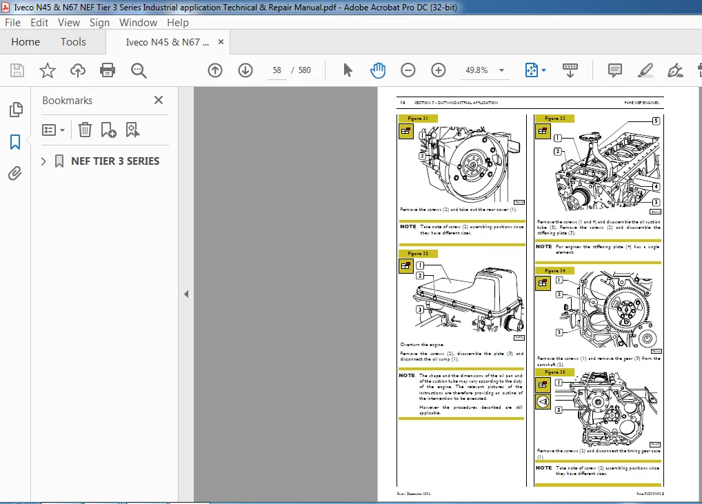
Disassembly of application components 52
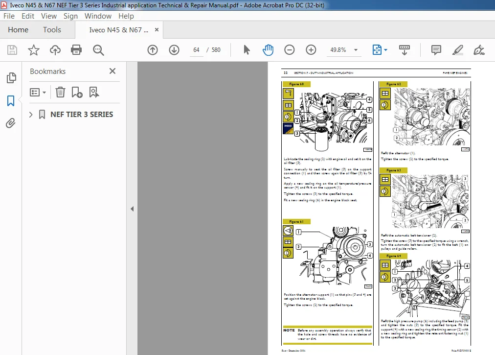
Assembly of application components 59
Completion of the engine 71
Checks and inspections 72
PART TWO – ELECTRICAL EQUIPMENT 73
LOCATION OF THE MAIN ELECTRICAL COMPONENTS 75
EDC7 ECU 76
Cable on engine 77
Injectors connector (A) 78
Sensors connector (C) 78
Crankshaft sensor 79
Timing sensor 79
Supercharging air pressure – temperature sensor 80
Engine oil temperature-pressure sensor 80
Fuel temperature and pressure sensor 81
Electro-injectors 82
Pre-post heating resistance and contactor 83
Coolant temperature sensor 84
Fuel temperature sensor 85
High pressure pump – pressure regulator 86
PART THREE – TROUBLESHOOTING 87
METHODS OF DIAGNOSIS 89
PT-01 89
PREFACE 90
PT-01 PORTABLE TESTER 91
Main functions 91
Test parameters 91
FAULT CODES 92
TROUBLESHOOTING 95
PART FOUR – MAINTENANCE PLANNING 97
MAINTENANCE PLANNING 99
Recovery 99
Regular maintenance and inspection planning 99
Checks not included in maintenance planning-daily checks 100
MAINTENANCE PROCEDURES 100
Checks and inspections 100
Engine oil level check 100
Combustion system inspection 101
Cooling system inspection 101
Lubricating system inspection 101
Inspection of water presence within fuel filter or pre-filter 101
Inspection/replacement of blow-by filter 102
Inspection of drive belt tensioning 102
Inspection and setting of tappet clearance 102
Oil motor and filter replacement 103
Fuel filter replacement 104
Alternator belt replacement 104
SECTION 4 – Overhaul and technical specifications 105
GENERAL SPECIFICATIONS 107
CLEARANCE DATA 108
4 AND 6 ENGINEOVERHAUL 115
ENGINE REMOVAL AT THE BENCH 115
REPAIR OPERATIONS 116
CYLINDER UNIT 116
Checks and measurements 116
Checking head supporting surface on cylinder unit 117
TIMING SYSTEM 118
Camshaft 118
Checking cam lift and pin alignment 119
BUSHES 119
Bush replacement 120
Tappets 120
Fitting tappets — camshaft 121
OUTPUT SHAFT 122
Measuring journals and crankpins 122
Measuring journals and crankpins (6 cyl ) 124
Replacing oil pump control gear 126
Fitting main bearings 126
Finding journal clearance 126
Checking crankshaft shoulder clearance 127
CONNECTING ROD — PISTON ASSEMBLY 127
Pistons 128
Measuring piston diameter 128
Piston pins 129
Connecting rods 130
Bushes 131
Fitting connecting rod-piston assembly 131
Connecting rod-piston coupling 131
Fitting split rings 132
Fitting connecting rod-piston assembly intocylinder barrels 132
Finding crankpin clearance 133
Checking piston protrusion 134
CYLINDER HEAD 135
Removing the valves 135
Checking cylinder head wet seal 136
Checking cylinder head supporting surface 136
VALVES 137
Removing carbon deposits, checking andgrinding valves 137
Checking clearance between valve stem and valve guide and valve centering 137
VALVE GUIDE 138
VALVE SEATS 138
Regrinding — replacing the valve seats 138
VALVE SPRINGS 140
FITTING CYLINDER HEAD 140
Refitting the cylinder head 141
TIGHTENING TORQUE 142
SECTION 5 – Tools 145
TOOLS 147
Appendix 153
SAFETY PRESCRIPTIONS 155
Standard safety prescriptions 155
Prevention of injury 155
During maintenance 155
Respect of the Environment 156
Part 2 – F4CE NEF ENGINES 157
UPDATING 159
SECTION 1 – General specifications 161
CORRESPONDENCE BETWEEN TECHNICAL CODE AND COMMERCIAL CODE 163
LUBRICATION 164
OIL VAPOUR RECIRCULATING SYSTEM 165
COOLING SYSTEM 166
AIR INDUCTION – BOOST DIAGRAM 167
Description 167
EXHAUSTGAS RE-CIRCULATIONSYSTEM (EGR) 168
SECTION 2 – Fuel 169
INJECTION FEED SYSTEM BY MECHANICAL ROTARY PUMP 171
FEED PUMP 173
PRIMING PUMP 174
FUEL FILTER 175
SECTION 3 – Industrial application 177
GENERAL INFORMATION 179
Version equipped with mechanical feed pump 179
Clearance data 180
PART ONE – MECHANICAL COMPONENTS 181
OVERHAUL OF THE ENGINE PROVIDED WITH MECHANICAL ROTARY PUMP 183
Preface 183
Engine setting operations for the assembly on turning stand 183
Disassembly of application components 184
Installation of application components 191
Completion of the engine 202
Rotary feed pump disassembly and assembly procedure 203
Feed system bleed procedure 206
Power takeoff 206
Checks and inspections 206
PART TWO – ELECTRICAL EQUIPMENT 207
ELECTRICAL COMPONET LAYOUT 209
Cooling liquid temperature sensor 210
Starter 210
Pre-post heating resistor 210
Pre-post heating unit 211
Electrical diagram pin out 211
KSBWater temperature sensor 211
Electromagnets assembled to feed pump 212
Oil pressure switch 212
Fuel filter 212
Speed sensor 213
Alternator 213
PART THREE – TROUBLESHOOTING 215
PART FOUR – MAINTENANCE PLANNING 223
MAINTENANCE PLANNING 225
Recovery 225
Planning of controls and periodical intervention 225
Checks not included in maintenance planning-daily checks 226
MAINTENANCE PROCEDURES 226
Checks and controls 226
Engine oil level check 226
Check of fuel system 227
Cooling system check 227
Lubricating system check 227
Check of water presence within fuel filter or pre-filter 227
Check of drive belt tensioning 228
Check of belt’s tear and wear status 228
Check and setting of tappet clearance 228
Oil motor and filter replacement 229
Fuel filter replacement 230
Alternator belt – water pump replacement 230
SECTION 4 – Overhaul and technical specifications 231
GENERAL SPECIFICATIONS 233
CLEARANCE DATA 234
INJECTION PUMP PUMPING ELEMENT PRE-LIFT TABLE 240
ENGINE OVERHAUL 241
ENGINE REMOVAL AT THE BENCH 241
REPAIR OPERATIONS 242
CYLINDER UNIT 242
Checks and measurements 242
Checking head supporting surface on cylinderunit 243
TIMING SYSTEM 243
Camshaft 243
Checking cam lift and pin alignment 244
BUSHES 244
Bush replacement 245
Tappets 245
Fitting tappets — camshaft 245
OUTPUT SHAFT 246
Measuring journals and crankpins 247
Replacing oil pump control gear 249
Fitting main bearings 249
Finding journal clearance 249
Checking output shaft shoulder clearance 250
CONNECTING ROD — PISTON ASSEMBLY 250
Pistons 251
Measuring piston diameter 251
Piston pins 252
Conditions for proper pin-piston coupling 252
Split rings 252
Connecting rods 253
Bushes 254
Fitting connecting rod-piston assembly 255
Connecting rod-piston coupling 255
Fitting split rings 255
Fitting connecting rod-piston assembly into cylinder barrels 256
Finding crankpin clearance 256
Checking piston protrusion 257
CYLINDER HEAD 258
Removing the valves 258
Checking cylinder head wet seal 259
Checking cylinder head supporting surface 259
VALVES 260
Removing carbon deposits, checking and grinding valves 260
Checking clearance between valve stem and valve guide and valve centering 260
VALVE GUIDE 261
VALVE SEATS 261
Regrinding — replacing the valve seats 261
VALVE SPRINGS 262
FITTING CYLINDER HEAD 263
Refitting the cylinder head 263
TIGHTENING TORQUE 264
SECTION 5 – Tools 267
TOOLS 269
Appendix 275
SAFETY PRESCRIPTIONS 277
Part 3 – F4DE NEF ENGINES 279
UPDATING 281
SECTION 1 – General specifications 283
CORRESPONDENCE BETWEEN TECHNICAL CODE AND COMMERCIAL CODE 285
LUBRICATION 286
COOLING SYSTEM 287
AIR INDUCTION BOOST DIAGRAM 288
Description 288
EXHAUSTGAS RE-CIRCULATION SYSTEM (EGR) 289
SECTION 2 – Fuel 291
COMMON RAIL 293
WORKING PROCESS 295
FUEL SYSTEM DIAGRAM 296
MECHANICAL FEEDING PUMP 297
CP3 HIGH PRESSURE PUMP 298
RAIL 302
RELIEF VALVE 302
ELECTRO-INJECTOR 303
PRESSURE LIMITER FOR FUEL RETURN 304
SECTION 3 – Industrial application 305
GENERAL SPECIFICATIONS 307
Section pictures of complete engine – common rail version 307
Clearance data – 6 cyl 308
PART ONE – MECHANICAL COMPONENTS 309
ENGINE OVERHAUL 311
Preface 311
Engine setting operations for the assembly on turning stand 311
Disassembly of application components 313
Assembly of application components 320
Checks and inspections 331
PART TWO – ELECTRICAL EQUIPMENT 333
LOCATION OF MAIN ELECTRICAL COMPONENTS 335
EDC7 ECU 336
Connector to injectors (A) 337
Feed connector (B) to components and to functions of the specific equipment 338
Connector to sensors (C) 339
Temperature and air-pressure sensor 340
Sensor of engine’s oil temperature and pressure 340
Driving shaft sensor 340
Timing system sensor 340
Fuel pressure sensor 341
Fuel temperature sensor 341
Resistor pre-post heating 341
Cooling liquid temperature sensor 341
Starter 342
Electro-injectors 342
PART THREE – TROUBLESHOOTING 343
PART FOUR – MAINTENANCE PLANNING 353
MAINTENANCE PLANNING 355
Recovery 355
Regular maintenance and inspection planning 355
Checks not included in maintenance planning-daily checks 356
MAINTENANCE PROCEDURES 356
Checks and inspections 356
Engine oil level check 356
Combustion system inspection 357
Cooling system inspection 357
Lubricating system inspection 357
Inspection of water presence within fuel filter or prefilter 357
Inspection of drive belt tensioning 357
Inspection and setting of tappet clearance 358
Oil motor and filter replacement 358
Fuel filter replacement 359
Alternator belt replacement 359
SECTION 4 – Overhaul and technical specifications 361
GENERAL SPECIFICATIONS 363
CLEARANCE DATA 364
ENGINE OVERHAUL 371
ENGINE REMOVAL AT THE BENCH 371
REPAIR OPERATIONS 372
CYLINDER UNIT 372
Checks and measurements 372
TIMING SYSTEM 373
Camshaft 373
Checking head supporting surface on cylinder unit 373
Checking cam lift and pin alignment 374
BUSHES 374
Bush replacement 375
Tappets 375
Fitting tappets — camshaft 375
OUTPUT SHAFT 376
Measuring journals and crankpins 376
Replacing oil pump control gear 379
Fitting main bearings 379
Finding journal clearance 379
Checking output shaft shoulder clearance 380
Pistons 381
Measuring piston diameter 381
Piston pins 382
Conditions for proper pin-piston coupling 382
Connecting rods 383
Bushes 384
Fitting connecting rod-piston assembly 384
Connecting rod-piston coupling 384
Fitting split rings 385
Fitting connecting rod-piston assembly into cylinder barrels 385
Finding crankpin clearance 386
Checking piston protrusion 387
CYLINDER HEAD 388
Removing the valves 388
Checking cylinder head wet seal 389
Checking cylinder head supporting surface 389
VALVES 390
Removing carbon deposits, checking and grinding valves 390
Checking clearance between valve stem and valve guide and valve centering 390
VALVE GUIDE 391
VALVE SEATS 391
Regrinding — replacing the valve seats 391
VALVE SPRINGS 393
FITTING CYLINDER HEAD 393
Refitting the cylinder head 394
TIGHTENING TORQUE 395
SECTION 5 – Tools 399
TOOLS 401
Appendix 407
SAFETY PRESCRIPTIONS 409
Standard safety prescriptions 409
Prevention of injury 409
During maintenance 409
Respect of the Environment 410
Part 4 – F4GE NEF ENGINES 411
SPECIAL REMARKS 413
SYMBOLS – ASSISTANCE OPERATIONS 414
UPDATING 415
SECTION 1 – General specifications 417
CORRESPONDENCE BETWEEN TECHNICAL CODE AND COMMERCIAL CODE 419
LUBRICATION 420
OIL VAPOUR RECIRCULATING SYSTEM 422
COOLING SYSTEM 423
AIR INDUCTION BOOST DIAGRAM 425
Boosting version engines 425
Description 425
AIR INDUCTION BOOST DIAGRAM 426
Description 426
EXHAUSTGAS RE-CIRCULATION SYSTEM (EGR) 427
SECTION 2 – Fuel 429
4-CYLINDER ENGINESWITH BOSCH VE 4/12 F ROTARY MECHANICAL PUMP 431
General information 431
Description of working principles 432
FEED PUMP 433
Example of identification 433
PRIMING PUMP 434
FUEL FILTER 435
6-CYLINDER ENGINESWITH BOSCH VE 6/12 F ROTARY MECHANICAL PUMP 436
General information 436
Description of working principles 437
PRIMING PUMP 438
FUEL FILTER 439
SECTION 3 – Industrial application 441
GENERAL INFORMATION 443
F4GE ENGINE CHARACTERISTICS 444
4-cylinder engines 444
6-cylinder engines 446
PART ONE – MECHANICAL COMPONENTS 447
OVERHAUL OF THE 4 CYLINDER ENGINE PROVIDED WITH MECHANICAL ROTARY PUMP 449
Preface 449
Engine setting operations for the assembly on turning stand 449
Disassembly of application components 450
Installation of rear components 459
Installation of rear components with reduced distribution 462
Flywheel installation 464
Installation of front components 464
Assembly of additional masses 466
Timing of additional masses 466
Completion of engine re-assembly 475
Rotary feed pump disassembly and assembly procedure 476
Feed system bleed procedure 479
Power take-off disassembly and assembly procedure 479
Checks and controls 480
OVERHAUL OF THE 6 CYLINDER ENGINE PROVIDED WITH MECHANICAL ROTARY PUMP 481
Preface 481
Engine setting operations for the assembly on turning stand 481
Removing components from application 482
Installation of front components 492
Completion of engine re-assembly 502
Checks and inspections 502
Rotary feed pump disassembly and assembly procedure 503
Feed system bleed procedure 506
Power take-off disassembly and assembly procedure 506
PART TWO – ELECTRICAL EQUIPMENT 507
ELECTRICAL COMPONENT LAYOUT (4 CYL ENGINES WITH ROTARY PUMP) 509
Cooling liquid temperature sensor 510
Starter 510
KSBWater temperature sensor 510
Electromagnets assembled to feed pump 511
Oil pressure sensor 511
Alternator 511
Pre-post heating resistor 511
ELECTRICAL COMPONENT LAYOUT (6 CYL ENGINES WITH ROTARY PUMP) 512
Cooling liquid temperature sensor 513
Starter 513
KSBWater temperature sensor 513
Oil pressure sensor 514
Alternator 514
Pre-post heating resistor 514
PART THREE – TROUBLESHOOTING 515
PART FOUR – MAINTENANCE PLANNING 523
MAINTENANCE PLANNING 525
Recovery 525
Planning of controls and periodical intervention 525
Checks not included in maintenance planning-daily checks 526
MAINTENANCE PROCEDURES 526
Checks and controls 526
Engine oil level check 526
Check of fuel system 527
Cooling system check 527
Lubricating system check 527
Check of water presence within fuel filter or pre-filter 527
Check of drive belt tensioning 528
Check of belt’s tear and wear status 528
Check and setting of tappet clearance 528
Oil motor and filter replacement 528
Fuel filter replacement 529
Alternator belt replacement 530
SECTION 4 – Overhaul and technical specifications 531
GENERAL SPECIFICATIONS 533
CLEARANCE DATA 534
TABLE OF PRE-DELIVERY VALUES FOR BOSCH INJECTION PUMPS VE 4/12 F – VE 6/12 F 540
ENGINE OVERHAUL 541
ENGINE REMOVAL AT THE BENCH 541
REPAIR OPERATIONS 542
CYLINDER UNIT 542
Checks and measurements 542
Checking head supporting surface on cylinderunit 543
TIMING SYSTEM 544
Camshaft 544
Checking cam lift and oin alignment 545
BUSHES 545
Bush replacement 547
Tappets 547
Fitting tappets — camshaft 547
OUTPUT SHAFT 548
Measuring journals and crankpins (4 cylinders) 548
Measuring journals and crankpins (6 cylinders) 550
Replacing oil pump control gear 552
Fitting main bearings 552
Finding journal clearance 552
Checking output shaft shoulder clearance 553
CONNECTING ROD — PISTON ASSEMBLY 553
Pistons 554
Measuring piston diameter 554
Piston pins 555
Conditions for proper pin-piston coupling 555
Split rings 555
Connecting rods 556
Bushes 557
Fitting connecting rod-piston assembly 557
Connecting rod-piston coupling 557
Fitting split rings 557
Fitting connecting rod-piston assembly into cylinder barrels 558
Finding crankpin clearance 558
Checking piston protrusion 559
CYLINDER HEAD 560
Removing the valves 560
Checking cylinder head wet seal 561
Checking cylinder head supporting surface 561
VALVES 562
Removing carbon deposits, checking and grinding valves 562
Checking clearance between valve stem and valve guide and valve centering 562
VALVE GUIDE 563
VALVE SEATS 563
Regrinding — replacing the valve seats 563
VALVE SPRINGS 564
FITTING CYLINDER HEAD 564
Refitting the cylinder head 565
TIGHTENING TORQUE (FOR 4 AND 6 CYL ) 566
SECTION 5 – Tools 569
TOOLS 571
Appendix 577
SAFETY PRESCRIPTIONS 579
PLEASE NOTE:
- This is the SAME manual used by the dealers to troubleshoot any faults in your vehicle. This can be yours in 2 minutes after the payment is made.
- Contact us at [email protected] should you have any queries before your purchase or that you need any other service / repair / parts operators manual.