Iveco Stralis AS Euro 4/5 Repair Manual – PDF DOWNLOAD
Original price was: $98.95.$29.95Current price is: $29.95.
Iveco Stralis AS Euro 4/5 Repair Manual – PDF DOWNLOAD
STRALIS AS EURO 4/5
REPAIR MANUAL
MECHANICAL
ELECTRIC/ELECTRONIC
Description
Iveco Stralis AS Euro 4/5 Repair Manual – PDF DOWNLOAD
FILE DETAILS:
Iveco Stralis AS Euro 4/5 Repair Manual – PDF DOWNLOAD
Format: PDF
Language: English
Brand: Iveco
DESCRIPTION:
Iveco Stralis AS Euro 4/5 Repair Manual – PDF DOWNLOAD
STRALIS AS EURO 4/5
REPAIR MANUAL
MECHANICAL
ELECTRIC/ELECTRONIC
”This document provides data, characteristics, instructions and methodology to perform repair interventions on the vehicle and its components. Anyhow, this document is addressed to qualified and specialised personnel. Iveco commercial and assistance network personnel as well as all Iveco authorised points of assistance are specifically qualified and equipped to perform the repair interventions that are indicated in this document. Before performing any intervention, check to have available the document relating to the vehicle model on which the intervention is being performed and also make sure that all accident prevention devices, such as, as a rough guide, goggles, helmet, gloves, shoes, as well as work tooling, lifting and transport tooling, etc., are available and efficient, and further make sure that the vehicle is put such a way that an intervention can be made in safety conditions.
- Making interventions strictly observing the indications given here, as well as using specific tooling indicated, assures a correct repair intervention, execution timing observance and operators’ safety. Each repair intervention must be finalised to the recovery of functionality, efficiency and safety conditions that are provided by Iveco. Each intervention, on the vehicle, that is finalised to a modification, alteration or else, which is not authorised by Iveco, involves the exclusion of any responsibility for Iveco, and, in particular, where the vehicle is covered by a guarantee, each such intervention involves an immediate lapse of the guarantee.
- Responsibility for Iveco in repair intervention execution is excluded. Iveco is available to provide all clarifications necessary tomake interventions, as well as to provide indications in cases and situations not included in this document. Data and information contained in this document could result not to be updated owing to modifications made by Iveco at any moment for technical or commercial reasons, or because of the need to adapt the vehicle to law requirements in different countries.
- In the case of a difference between what contained here and what actually found on the vehicle, please contact Iveco network before making any intervention.” The data contained in this publication might fail to reflect the latest changes which the Manufacturer may introduce at any time, for technical or sales purposes, or to meet the requirements of local legislation. Copy, even partial, of text and drawings is forbidden.
TABLE OF CONTENTS:
Iveco Stralis AS Euro 4/5 Repair Manual – PDF DOWNLOAD
STRALIS AS EURO 4/5 1
REPAIR MANUAL 1
MECHANICAL ELECTRIC/ELECTRONIC 1
PRELIMINARY REMARKS 3
SYMBOLS -WARNINGS 3
SYMBOLS – ASSISTANCE OPERATIONS 4
PRODUCT CODE 5
GENERAL WARNINGS 6
GENERAL WARNINGS ON THE ELECTRIC SYSTEM 8
Bonding and screening 10
OPTIONAL ELECTRICAL AND MECHANICAL PARTS INSTALLATIONS 11
CONVERSIONS BETWEEN THE MAIN UNITS OF MEASUREMENT OF THE INTERNATIONAL SYSTEM AND MOST USED DERIVED QUANTITIES 11
UPDATE DATA 13
INDEX OF SECTIONS 15
SECTION 1 – General 17
General 17
VEHICLE IDENTIFICATION DATA 19
Vehicle Identification Plate 20
Production identification plate 20
COMMERCIAL CODES 21
COMPOSITION OF MODELS 23
P I C NUMBER CODING 25
REPLENISHING FLUIDS 29
International lubricant designation 31
SECTION 2 – Engine 33
Engine 33
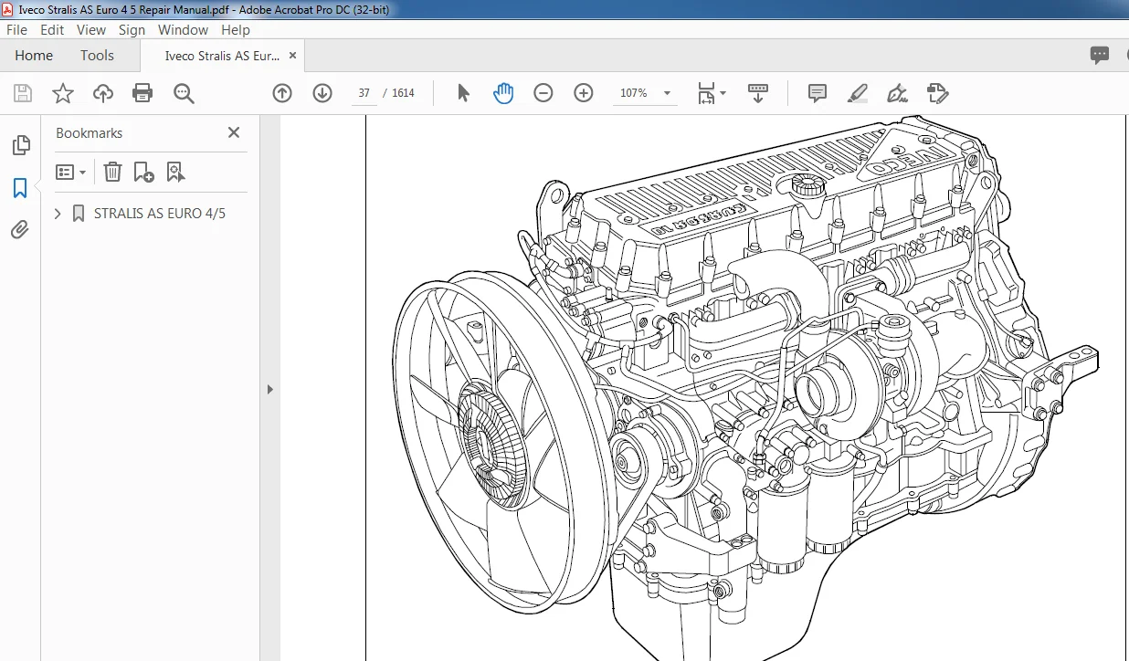
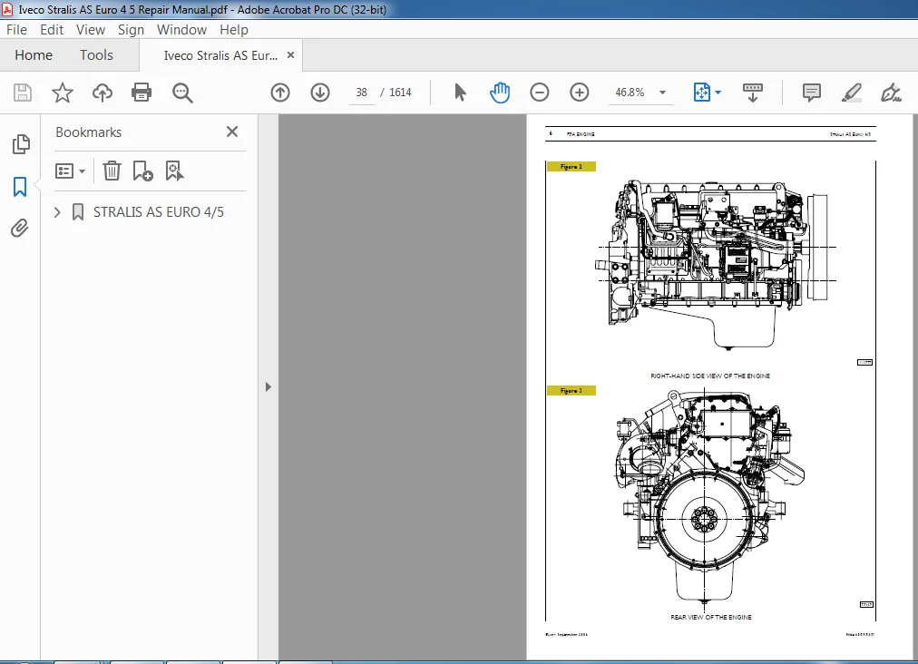
F3A Engine 35
VIEWS OF THE ENGINE 37
TECHNICAL DESIGNATION 41
CHARACTERISTIC CURVES 42
GENERAL CHARACTERISTICS 44
ASSEMBLY CLEARANCE DATA 47
TIGHTENING TORQUE F3A ENGINE 54
TOOLS 61
ENGINE REMOVAL – REFITTING 71
Removal 71
Refitting 72
Filling the cooling system 73
Bleeding air from the supply system 74
Checks and tests 74
ELECTRO-MAGNETIC JOINT REPLACEMENT 75
Removal 75
Refitting 76
DISMANTLING THE ENGINE ON THE BENCH 79
REPAIR OPERATIONS 86
CYLINDER BLOCK 86
Checks and measurements 86
Cylinder liners 87
Replacing cylinder liners 88
Crankshaft 89
Measuring the main journals and crankpins 90
Preliminary measurement of main and big end bearing shell selection data 91
Selecting the main and big end bearing shells 92
Replacing the timing gear and oil pump 98
Checking main journal assembly clearance 98
Checking crankshaft end float 99
Piston connecting rod assembly 100
Piston rings 102
Connecting rods 103
Bushings 104
Checking connecting rods 104
Mounting the connecting rod — piston assembly 105
Mounting the piston rings 105
Fitting the big end bearing shells 105
Fitting connecting rod – piston assemblies in the cylinder liners 106
Checking piston protrusion 106
Checking crankpin assembly clearance 107
CYLINDER HEAD 107
Disassembly the valves 107
Checking head bearing surface on cylinder block 107
Valves 108
Removing deposits and checking the valves 108
Valve seats 108
Checking clearance between valve-stem and associated valve guide 109
Valve guides 109
Replacing injector cases 109
Checking injector protrusion 111
TIMING GEAR 112
Camshaft drive 112
Idler gear pin 112
Idler gear 112
Twin intermediategearpin 112
Twin idler gear 112
Replacing the bushings 112
Timing system 113
Checking cam lift and pin alignment 113
Bushings 114
Replacing camshaft bushings with drift 99360499 115
Removal 115
Assembly 115
Valve springs 116
ROCKER SHAFT 117
Shaft 118
Rocker arms 118
ENGINE ASSEMBLY ON BENCH 119
Fitting connecting rod – piston assemblies in cylinder liners 122
ENGINE FLYWHEEL 125
Fitting engine flywheel 125
Fitting camshaft 126
Fitting pump-injectors 127
Fitting rocker-arm shaft assembly 127
Camshaft timing 128
Phonic wheel timing 130
Intake and exhaust rocker play adjustment and pre-loading of rockers controlling pump injectors 131
Completing Engine Assembly 132
LUBRICATION 135
Oil pump 137
Overpressure valve 137
Oil pressure control valve 138
Heat exchanger 138
By-pass valve 139
Thermostatic valve 139
Engine oil filters 139
Valve integrated in piston cooling nozzle 140
COOLING 141
Description 141
Operation 141
Electromagnetic coupling 143
Water pump 143
Thermostat 143
View of thermostat operation for versions with Intarder 144
TURBOCHARGING 145
Turbocharger HOLSET HE 531 V 145
Actuator 146
Solenoid valve for VGT control 146
REPAIRING ACTIONS 146
Variable geometry movement control 147
Checking the actuator 147
Checking actuator travel 148
Cleaning turbine body 148
FEEDING 151
Overpressure valve 152
Feed pump 152
Injector-pump 152
Replacing injectors-pump 153
Pressure damper 153
F3B Engine 155
VIEWS OF THE ENGINE 157
TECHNICAL DESCRIPTION 160
CHARACTERISTIC CURVES 161
GENERAL SPECIFICATIONS 163
ASSEMBLY DATA – CLEARANCE 166
TIGHTENING TORQUE 173
DIAGRAMS OF TIGHTENING SEQUENCE OF MAIN ENGINE COMPONENTS 176
TOOLS 180
ENGINE REMOVAL-REFITTING 191
Removal 191
Refitting 194
Filling the cooling system 195
Bleeding air from the supply system 196
Checks and tests 196
ELECTRO-MAGNETIC JOINT REPLACEMENT 197
Removal 197
Refitting 198
DISASSEMBLY THE ENGINE ON THE BENCH 201
REPAIRS 209
CYLINDER BLOCK 209
Checks and measurements 209
Cylinder liners 210
Replacing the cylinder liners 211
Crankshaft 212
Measuring the main journals and crankpins 213
Preliminary measurement of data to select main bearing and big end bearing shells 214
Selecting the main bearing and big end bearing shells 215
Replacing the timing gear and oil pump 221
Checking main journal assembly clearance 221
Checking crankshaft end float 222
Connecting rod piston assembly 223
Piston rings 225
Connecting rod 226
Bushings 227
Checking connecting rods 227
Mounting the connecting rod — piston assembly 228
Mounting the piston rings 228
Fitting the big end bearing shells 228
Fitting connecting rod – piston assemblies in the cylinder liners 229
Checking piston protrusion 229
Checking crankpin assembly clearance 230
CYLINDER HEAD 230
Disassembly the valves 230
Checking head bearing surface on cylinder block 230
Valves 231
Valve seats 231
Checking clearance between valve-stem and associated valve guide 232
Valve guides 232
Replacing injector cases 232
Checking injector protrusion 234
TIMING GEAR 235
Camshaft drive 235
Idler gear pin 235
Idler gear 235
Twin intermediate gear pin 235
Twin idler gear 235
Replacing the bushings 235
Timing system 236
Checking cam lift and pin alignment 236
Bushings 237
Valve springs 239
ROCKER SHAFT 240
Shaft 241
Rocker arms 241
ENGINE ASSEMBLY ON BENCH 242
Fitting connecting rod – piston assemblies in cylinder liners 245
Fitting the cylinder head 246
Fitting flywheel box 247
ENGINE FLYWHEEL 248
Fitting engine flywheel 248
Fitting camshaft 249
Fitting pump-injectors 250
Fitting rocker-arm shaft assembly 250
Camshaft timing 251
Phonic wheel timing 253
Adjusting rocker arm clearance, intake, exhaust and pre-load of pump injector governing rocker arms 254
Completing Engine Assembly 255
LUBRICATION 259
Oil pump 261
Overpressure valve 261
Oil pressure control valve 262
Heat exchanger 262
By-pass valve 263
Thermostatic valve 263
Engine oil filters 263
Valve integrated in piston cooling nozzle 264
COOLING 265
Description 265
Operation 265
Electromagnetic coupling 267
Water pump 267
Thermostat 267
View of thermostat operation for versions with Intarder 268
TURBOCHARGING 269
Turbocharger HOLSET HE 551 V 269
Actuator 270
Solenoid valve for VGT control 270
REPAIR 270
Variable geometry movement control 271
Checking the actuator 271
Checking actuator travel 272
Cleaning turbine body 272
FEEDING 275
Overpressure valve 276
Feed pump 276
Injector-pump 276
Pressure damper 276
Hydrocar pressure take-off on timing system 277
HYDROCAR PRESSURE TAKE-OFF ON TIMING SYSTEM – P T O (OPTIONAL) 279
Description 279
SPECIFICATIONS AND DATA 280
TIGHTENING TORQUES 281
ENGAGING POWER TAKE-OFF 282
REMOVING-REFITTING POWER TAKE-OFF 282
Denox System 2 283
DeNOx2 SYSTEM 285
General remarks 285
Tank 287
Ad Blue fluid level gauge control 287
By-pass valve 287
Pump module 288
Dosing module 288
Catalyst 288
Exhaust gas temperature sensor 289
Humidity detecting sensor 290
REPAIR INTERVENTIONS ON DeNox SYSTEM 291
Ad Blue tank 291
Disconnection 291
Reconnection 291
Tank level indicator 292
Disconnection 292
Reconnection 292
Pump module 292
Disconnection 292
Filter + Pre-Filter 293
Disconnection 293
Reconnection 293
Deflecting valve 293
Disconnection 293
Inlet exhaust gas temperature sensor 293
Disconnection 293
Reconnection 294
Outlet exhaust gas temperature sensor 294
Disconnection 294
Reconnection 294
Nitrogen oxides detecting sensor (IF PRESENT) 294
Disconnection 294
Reconnection 295
Sucked air humidity detecting sensor 295
Disconnection 295
Reconnection 295
Measuring out module 295
Disconnection 295
Reconnection 295
Fault Diagnosis 297
FAULT DIAGNOSIS 299
Diagnosis Instruments 299
Cluster Diagnosis 301
DTC – FMI error codes 303
SECTION 3 – Clutch 327
Clutch 327
DESCRIPTION 329
Clutch 329
SPECIFICATIONS AND DATA 329
DIAGNOSTICS 331
Main operating faults of a mechanical nature 331
TIGHTENING TORQUES 332
TOOLS 332
REMOVING AND REFITTING THE CLUTCH 333
Removal 333
CHECKS 333
Refitting 334
REMOVING-REFITTING THE THRUST BEARING 334
REPLACING THE SUPPORT BEARING OF THE CLUTCH SHAFT 334
REMOVING-REFITTING THE PEDAL UNIT SATA 335
Removal (vehicles with EuroTronic Automated gearbox) 335
Removal (vehicles with ZF 16 S gearbox) 336
Refitting 337
PEDAL TYPE SATA (Vehicles with ABS) 337
Unit removal-assembly 337
CHECKING AND ADJUSTING STOPS ON CLUTCH PEDAL (vehicles with ABS) 338
Clutch stop 338
Idle travel of clutch pedal 338
Pedal control valve stroke 338
PEDAL TYPE WABCO vehicles with EBS) 339
Clutch stop 339
Clutch pedal idle travel 339
Pedal control valve stroke 339
HYDRAULIC CONTROL vehicles with ZF 16 S gearboxes) 340
Clutch actuator 341
SPECIFICATIONS FOR MANUAL GEARBOX PREASSEMBLY 342
Spring pin adjustment 342
BLEEDING CLUTCH CIRCUIT 343
SPECIFICATIONS FOR AUTOMATIC TRANSMISSION ASSEMBLY 344
SECTION 4 – Gearboxes 345
Gearboxes 345
Gearboxes: ZF 16 S 1920 T D , ZF 16 S 2220 T D /T O , ZF 16 S 2320 T D , ZF 16 S 2520 T O 347
DESCRIPTION 349
LOCATION OF GEARBOX DESCRIPTION PLATE 350
SPECIFICATIONS AND DATA 351
SPECIFICATIONS AND DATA 352
TIGHTENING TORQUES 353
TOOLS 354
REMOVING-REFITTING THE GEARBOX 355
Removal 355
Refitting 356
ZF gearboxes with Intarder (IT), hydraulic retarder, types: ZF 16 S 1921 T D , ZF 16 S 2221 T D /T O , ZF 16 S 2321 T D , ZF 16 S 2521 T O 357
SPECIFICATIONS AND DATA 359
TOOLS 360
OVERHAULING THE GEARBOX 367
Removing the hydraulic retarder from the gearbox on the stand 367
Refitting the hydraulic retarder 368
Adjusting stator end float 368
Removing the epicyclic reduction gear unit ERG) rear box 370
Removing the epicyclic reduction gear unit (ERG) 370
Refitting the epicyclic reduction gear unit (ERG) rear box 375
Gearboxes EuroTronic Automated: – 12 AS 1930 T D – 12 AS 2330 T D /T O – 12 AS 2530 T O 377
DESCRIPTION 379
LOCATION OF GEARBOX DESCRIPTION PLATE 379
GEARBOX ELECTRONIC MANAGEMENT 380
Theoretical scheme 380
SPECIFICATIONS AND DATA 382
TIGHTENING TORQUES 383
TOOLS 384
REMOVING-REFITTING GEARBOX 385
Removal 385
Refitting 385
Gearboxes EuroTronic Automated with Intarder: – 12 AS 1931 T D – 12 AS 2331 T D /T O – 12 AS 2531 T O 387
SPECIFICATIONS AND DATA 389
TOOLS 390
EXPERIMENTAL TOOLS 391
OVERHAULING THE GEARBOX 392
Removing the hydraulic retarder 392
Refitting the hydraulic retarder 393
Adjusting epicyclic reduction gear train bearing end float 393
Adjusting stator end float 394
Adjusting stator end float 395
Removing the rear box 396
Disassembling the E R G 396
Assembling the E R G 398
EuroTronic gearboxes diagnostics 403
DIAGNOSTICS 405
Diagnosis Instruments 405
Cluster Diagnosis 407
Troubleshooting via DTC-FMI codes 409
SECTION 5 – Intarder – ZF hydraulic retarder 501
Intarder – ZF hydraulic retarder 501
LOCATION OF INTARDER HYDRAULIC RETARDER DESCRIPTION PLATE 503
GENERAL INFORMATION 504
OPERATION 504
Retarder engaged 505
Retarder disengaged 506
LAYOUT OF MAIN SYSTEM COMPONENTS ON THE RETARDER 507
REMOVING AND REFITTING THE RETARDER ON THE ZF 16 S 1621/1921/2221 GEARBOX 508
Removal 508
Refitting 509
Filling with oil 509
SPECIFICATIONS AND DATA 510
TIGHTENING TORQUES 511
TOOLS 512
DIAGNOSTICS 514
Main operating faults of a mechanical nature 514
OVERHAULING THE INTARDER HYDRAULIC RETARDER 516
Hydraulic accumulator 516
Removal 516
Fitting 516
Removing hydraulic retarder 516
Checking the component parts of the hydraulic retarder 521
Fitting the hydraulic retarder 522
Stator end float adjustment 527
Only for EuroTronic Automated gearboxes, operate as below 527
SECTION 6 – Propeller shafts 529
Propeller shafts 529
CHARACTERISTICS AND DATA 531
STRALIS (Tractors) – CHARACTERISTICS AND DATA (vehicles 4×2/6x2C/6×4/6x2p) 533
STRALIS AS (Cabs) – CHARACTERISTICS AND DATA (vehicles 4×2/6x2P/6×4) 534
DIAGNOSTIC 535
Main operating faults of a mechanical nature 535
TIGHTENING TORQUES 536
TOOLS 536
REMOVING AND REASSEMBLING THE PROPELLER SHAFT 537
Removal 537
Reassembly 537
CHECKING THE PROPELLER SHAFT ON THE VEHICLE 538
REMOVING AND FITTING BACK THE UNIVERSAL JOINTS 539
REMOVING AND REASSEMBLING THE SUPPORT 539
SECTION 7 – Rear axles 541
Rear axles 541
DIAGNOSTICS 543
Main operating faults of a mechanical nature 543
REMOVING-REFITTING THE REAR AXLE 545
Removal 545
Refitting 545
REMOVING-REFITTING THE DIFFERENTIAL FROM THE REAR AXLE ON THE VEHICLE 546
Removal 546
Refitting 546
Rear Axle ARVINMERITOR MS 13-175 with disc brakes 547
LOCATION OF DIFFERENTIAL UNIT PLATES – REAR AXLE 549
DESCRIPTION 550
CHARACTERISTICS AND DATA 551
TIGHTENING TORQUES 552
TOOLS 554
OVERHAULING THE REAR AXLE ASSEMBLY 559
OVERHAULING THE WHEEL HUBS 559
Removal 559
Replacing wheel hub bearings 561
Checking the parts forming the wheel hubs 561
Replacing the wheel fixing pins 561
REMOVING AND REFITTING THE DIFFERENTIAL with axle on stand 99322215) 565
Removal 565
Refitting 565
REPAIRING THE DIFFERENTIAL 566
Removing the differential 566
Removing the gearcase 567
REMOVING THE BEVEL PINION FROM THE SUPPORT 569
Differential component check 569
Fitting the gear housing 570
FITTING THE MOUNT ON THE BEVEL PINION 571
Reassembling the differential housing 573
ADJUSTING THE CAP GAP 575
CORRECTING THE CROWNWHEEL AND PINION CONTACTS (AFTER ASSEMBLY) 578
WORK ON THE VEHICLE 581
REPLACING THE BEVEL PINION MOUNT SEAL 581
Disassembly 581
Assembly 582
Rear axle 451391 583
DESCRIPTION 585
SPECIFICATIONS AND DATA 586
TIGHTENING TORQUES 587
TOOLS 589
REAR AXLES ASSEMBLY OVERHAUL 595
Disassembly 595
Epicycloid reduction gear disassembly 595
Wheel hub disassembly 596
CHECKING THE WHEEL HUB AND EPICYCLOID REDUCTION GEAR UNIT PARTS 598
WHEEL HUB ASSEMBLY 599
Assembling the epicycloid reduction gear 601
REMOVING-REFITTING THE DIFFERENTIAL 604
REPAIRING THE DIFFERENTIAL 606
Disassembly 606
Gear housing disassembly 607
Removing the bevel pinion from the support 608
CHECKING THE DIFFERENTIAL COMPONENTS 610
Gear housing assembly 611
Assembling the bevel pinion support 612
Procedure to follow to determine the thickness of the bevel pinion rolling torque adjusting ring 612
Differential housing assembly 614
Gear housing bearings rolling torque adjustment 615
Axles in tandem ARVINMERITOR MT23-155/2D 619
Axles Intermediate ARVINMERITOR MD11-155/2D 621
DESCRIPTION 623
SPECIFICATIONS ANDA DATA 623
LOCATION OF DIFFERENTIAL UNIT PLATES – REAR AXLE 624
SPECIFICATIONS AND DATA 625
TIGHTENING TORQUES 627
TOOLS 629
SPECIAL PURPOSE TOOLS 635
INTERMEDIATE REAR AXLE ASSEMBLY OVERHAUL 636
OVERHAULING THEWHEEL HUBS 636
Removal 636
Replacing wheel hub bearings 638
Checking the parts forming the wheel hubs 638
Replacing the wheel fixing pins 638
Wheel hub reassembly 639
DIFFERENTIAL CASE REMOVAL 642
Case removal 642
Gearing case removal 648
Checking the differential components 649
Gearing case refitting 649
ASSEMBLING DIFFERENTIAL CASING 651
Calculating bevel pinion position in differential casing 651
EXAMPLES 651
Adjust the limit switch of the differential – distributor lock control pin 655
Adjusting drive input shaft bearing end float 656
ADJUSTING THE CAP ANGLE 657
CORRECTING THE BEVEL GEAR PAIR CONTACTS (AFTER FITTING IN PLACE) 660
REMOVAL-OVERHAUL-REFITTING OF DISTRIBUTOR OUTPUT SHAFT 663
Adjustment of motion output shaft bearing end play 664
Rear axles ARVINMERITOR MR11-155/D 665
DESCRIPTION 667
LOCATION OF DIFFERENTIAL UNIT PLATES – REAR AXLE 668
CHARACTERISTICS AND DATA 669
TIGHTENING TORQUES 670
REPAIR OPERATIONS 672
SECTION 8 – Axles 673
Axles 673
Front axles 673
Front axle 5876 5876/4 5876/5 Steering central added axle 5876/4 675
DESCRIPTION 677
SPECIFICATIONS AND DATA 678
DIAGNOSTICS 680
Main operating faults of a mechanical nature 680
TIGHTENING TORQUES 681
TOOLS 683
REMOVING AND REFITTING AXLE 687
Vehicles with mechanical front suspension 687
Removal 687
Refitting 687
REMOVING AND REFITTING AXLE 688
Vehicles with pneumatic front suspension and longitudinal bars 688
Removal 688
Refitting 689
HYDRAULIC SYSTEM FOR CENTRAL ADDED AXLE STEERING (vehicles 6X2C) 690
Hydraulic system working diagram 690
CHARACTERISTICS AND DATA 691
CENTRING CYLINDER OPERATING DIAGRAM 692
Added central axle 692
Location on the vehicle of the main components of the hydraulic system 693
Hydraulic system 694
AIR BLEEDING FROM THE HYDRAULIC CIRCUIT 695
Filling up and bleeding the power steering hydraulic circuit (circuit 1) 696
Filling up and bleeding the power steering hydraulic circuit (circuit 2) 696
REPAIRS 697
CENTRAL ADDED AXLE AIR LIFT, 6X2C VEHICLES 697
GENERAL 697
Location on the vehicle of the main components 698
Pneumatic principle scheme, rear pneumatic suspensions and pneumatic lifting device for central added axle with single wheels 699
VEHICLE CHECKS 700
Tie rods 700
Swivel heads 700
CHECKING SWIVEL HEAD PLAY 700
FRONT AXLE ASSEMBLY OVERHAUL 701
REMOVING – REFITTING WHEEL HUBS 701
Removal 701
Replacing wheel hub bearings 702
Replacing wheel fixing pins 703
Refitting wheel hubs 703
Checking wheel hub bearing end float 703
Measuring rolling torque 704
REMOVING AND REFITTING TRANSVERSE TIE ROD 704
REPLACING TRANSVERSE TIE ROD SWIVEL HEADS 705
LONGITUDINAL TIE ROD LEVER REMOVAL/REFITTING 705
CROSS TIE ROD LEVER REMOVAL/REFITTING 705
REMOVING AND REFITTING PIN FOR STUB AXLE 705
Removal 705
Replacing kingpin bearing 706
Checking and adjusting clearance between stub axle and axle 707
CHECKING AND MEASURING THE AXLE BODY 708
Checking levelness of leaf spring supporting surfaces with respect to the holes for the kingpins 708
Checking angle of holes for kingpins 709
Additional rear axle 673
Rigid rear added axle 55080/DI 711
DESCRIPTION 713
CHARACTERISTICS AND DATA 714
TIGHTENING TORQUE 715
TOOLS 716
REMOVING-REFITTING 718
Removal 718
Refitting 719
REPAIRS 719
Rigid rear added axle with hydraulic lifting 56082/D1 (N 9171) 721
DESCRIPTION 723
CHARACTERISTICS AND DATA 724
TIGHTENING TORQUE 725
TOOLS 726
REMOVING-REFITTING 727
REPAIRS 727
Steering rear added axle with pneumatic lifting 57080/DI 729
DESCRIPTION 731
CHARACTERISTICS AND DATA 732
TIGHTENING TORQUES 734
TOOLS 735
REPAIRS 739
PNEUMATIC LIFT 739
GENERAL 739
LOCATION ON THE VEHICLE OF THE MAIN COMPONENTS OF THE HYDRAULIC SYSTEM 740
HYDRAULIC SYSTEM 741
HYDRAULIC SYSTEM WORKING DIAGRAM 742
VEHICLES WITH PNEUMATIC REAR SUSPENSIONS AND PNEUMATIC LIFTING 743
Location on the vehicle of the main components 743
Pneumatic principle scheme, rear pneumatic suspensions and pneumatic lifting device for rear added axle with single wheels 744
DIAGNOSTICS 745
Main operating faults of a mechanical nature 745
TIGHTENING TORQUES (Steering and lifting device linkage) 746
CHARACTERISTICS AND DATA 747
Steering and third axle hydraulic system 747
MAIN HYDRAULIC SYSTEM COMPONENTS 748
HYDRAULIC ACCUMULATOR 748
Nitrogen pressure checking and recharging 748
OPERATOR CYLINDER 748
Disassembly 749
Assembly 749
Checking cylinder oil sealing on the vehicle 749
CENTRING CYLINDER 749
Disassembly 750
Assembly 750
Checking cylinder oil sealing on the vehicle 750
ADDITIONAL AXLE PNEUMATIC LIFTING DEVICE REMOVAL AND REFITTING 751
Removal 751
Refitting 751
AIR BLEEDING FROM THE HYDRAULIC CIRCUIT 752
Filling up and bleeding the power steering hydraulic circuit (circuit 1) 753
Filling up and bleeding the power steering hydraulic circuit (circuit 2) 753
Wheel geometry 755
GENERAL INFORMATION 757
Steering wheel angles 757
FRONT WHEEL GEOMETRY (4X2 vehicles) 758
Positioning clips and headlights 758
Electronic compensation of rim eccentricity 759
Wheel alignment 759
Checking wheel toe-in 760
Checking wheel deviation 760
Checking camber 760
Checking kingpin angle and caster 761
Checking rear axle alignment 762
Vehicle wheel geometry with steering rear added axle and pneumatic lifting 762
Wheel setup for vehicles with additional centralsteering axle and pneumatic lift 763
SECTION 9 – Suspensions 765
Suspensions 765
SUSPENSIONS 769
DESCRIPTION 769
Mechanical front suspension 769
Pneumatic front suspension 769
Pneumatic rear suspension 769
SPECIFICATIONS AND DATA 770
Models front suspension: 4×2 (tractors) 770
Models front suspension: 4×2 (tractors) – 6×4 (tractors and cab-equipped vehicles) 771
Models front suspension: 4×2 (tractors) – 6×4 (tractors and cab-equipped vehicles) 772
Models front suspension: 4×2 (cab-equipped vehicles) – 6x2C (tractors) – 6x2P (tractors and cab-equipped vehicles) 773
Models front suspension: 4×2 (tractors and lorries) – 6x2P (tractors and lorries) 775
Models front suspension: 4×2 (tractors and cab-equipped vehicles) – 6x2P (cab-equipped) vehicles with pneumatic front suspension 776
MECHANICAL FRONT SUSPENSION ASSEMBLY DRAWING 777
PNEUMATIC FRONT SUSPENSION ASSEMBLY 780
CENTRAL ADDED AXLE SUSPENSION ASSEMBLY 781
Leaf spring for central added axle (vehicles with air suspension) 6x2C vehicles 782
Front shock absorbers 783
Additional axle shock absorbers 784
Rear shock absorbers 785
PNEUMATIC SUSPENSION 786
Chassis frame lifting, lowering and self-levelling with remote control 786
Saving Levels 786
AXLE LOAD METER 787
Activating function 787
CALIBRATION (indication on display unit) 787
SCHEMES OF AIR SPRING SUSPENSIONS SYSTEMS 789
Principle scheme of rear air spring suspensions for lorries 4×2/P 789
Principle scheme of suspensions for lorries 4×2/FP 790
Principle scheme of air spring suspensions for lorries 4x2FP-CM 791
Working diagram of pneumatic rear suspensions for 4x2T/P tractors 792
Working diagram of suspensions for 4x2T/FP-LT 793
Working diagram of pneumatic suspensions for tractors 6x2TX/P (without added axle lifter) 794
Working diagram of pneumatic suspensions for tractors 6x2TX/P (with added axle lifter) 795
Principle scheme of rear air spring suspensions for lorries 6x2Y/PS (with added axle lifter) 796
Principle scheme of rear air spring suspensions for lorries 6x2Y/PS (without added axle lifter) 797
Principle scheme of rear air spring suspensions for lorries 6x2Y/PT and tractors 6x2TY/PT (with added axle lifter) 798
Principle scheme of rear air spring suspensions for lorries 6x2Y/PT and tractors 6x2TY/PT (without added axle lifter) 799
Principle scheme of air spring suspensions for lorries 6x2Y/FP/FS-CM (with added axle lifter) 800
Principle scheme of air spring suspensions for lorries 6x2Y/FP/FS-CM (without added axle lifter) 801
Principle scheme of air spring suspensions for lorries 6x2Y/FP/FS-GV (with added axle lifter) 802
Principle scheme of air spring suspensions for lorries 6x2Y/FP/FS-GV (without added axle lifter) 803
Working diagram of pneumatic rear suspensions for 6×4 tractors and lorries 804
CHARACTERISTICS AND DATA 805
Pneumatic System 805
MAIN COMPONENTS OF THE PNEUMATIC SYSTEM 806
Fault Diagnosis 806
Controlled pressure valve 806
Level sensor 806
Electro-Pneumatic Control Valve 807
Load detector pressure sensor 808
Low air pressure switch 808
Air spring 808
ECAS Control Unit 808
DIAGNOSTICS 809
Diagnosis Instruments 809
Cluster Diagnosis 811
Troubleshooting via DTC-FMI codes 813
TOOLS 842
SPECIAL PURPOSE TOOLS 844
TIGHTENING TORQUES 845
Mechanical front suspension 845
Pneumatic front suspension 846
Pneumatic front suspension with bars 847
Central added axle pneumatic suspensions 6×2 C vehicles 848
Pneumatic rear suspension 4×2 – 6×2 C vehicles 849
Pneumatic rear suspension 6×2 P/PT vehicles 851
Pneumatic rear suspension 6×2 P/PS vehicles 852
Pneumatic rear suspension 6×2 P/FP/FS vehicles (version for 3800 to 5500 wheel bases) 853
Pneumatic rear suspension 6×2 P/FP/FS vehicles (version for 5700 to 6050 wheel bases) 854
Pneumatic rear suspension 6×4 P vehicles 855
REMOVAL-REFITTING OF FRONT LEAF SPRING 856
Removal 856
Refitting 856
REMOVING-REFITTING FRONT SUSPENSION BARS 857
Removing longitudinal bars 857
Removing transverse bar 857
Refitting 857
REAR SUSPENSIONS 859
Removal 859
Refitting 859
REMOVING-REFITTING THE REAR AXLE LONGITUDINAL SUSPENSION ARM 860
REMOVING-REFITTING THE REAR ADDED AXLE LONGITUDINAL SUSPENSION ARM 860
REMOVING-REFITTING THE REAR AXLE TRIANGULAR SUSPENSION ARM 860
REMOVING-REFITTING THE REAR ADDED AXLE TRIANGULAR SUSPENSION ARM 860
Removal 860
Refitting 860
REPLACING THE SUSPENSION ARM FLEXIBLE PIN 861
Dismounting 861
Mounting 861
REPLACING TRIANGULAR SWINGING ARM BALL ARTICULATED JOINT 861
Dismounting 862
Mounting 862
STABILIZER BAR 864
FRONT STABILIZER BAR 864
CENTRAL ADDED AXLE STABILIZER BAR (6×2 C vehicles) 864
REAR STABILIZER BAR 864
REAR ADDED AXLE STABILIZER BAR (6x2P vehicles) 864
Removal 864
Refitting 864
RUBBER BUSHINGS 867
Replacing front stabilizer bar rubber bushings 867
Replacing rear stabilizer bar rubber bushings 867
SHOCK ABSORBERS 868
Removal-refitting 868
Central added axle shock absorbers 868
Rear axle shock absorbers 868
Rear added axle shock absorbers 6×2 P vehicles) 868
Removal 868
Refitting 868
CHASSIS FRAME ADJUSTMENT 869
SECTION 10 – Wheels and tyres 875
Wheels and tyres 875
DESCRIPTION 877
CHARACTERISTICS AND DATA 877
Tyre inflation pressures 877
TOOLS 878
DIAGNOSTICS 878
Main operating faults of a mechanical nature 878
STATIC BALANCING OF THE WHEELS 880
CORRECTING RESIDUAL STATIC IMBALANCE 881
TYRE PRESSURE 881
HOW TYRE BEHAVIOUR DEPENDS ON PRESSURE 882
SECTION 11 – Steering 883
Steering 883
DESCRIPTION 885
SPECIFICATIONS AND DATA 886
Scheme of the steering control of vehicles with mechanical front suspension 887
Vehicle steering control diagram with front air suspension and longitudinal bars 888
Vehicle steering control diagram with front air suspension and leaf springs 889
Scheme of the steering control of 6×2 p vehicles – having a steering rear axle – with mechanical front suspension 890
Scheme of the steering control of 6×2 p vehicles – having a steering rear axle – with pneumatic front suspension 891
Scheme of the steering control of 6×2 p vehicles – having a steering rear axle – with pneumatic front suspension and longitudinal bars 892
Scheme of the steering control of 6×2 c vehicles – having a steering central axle -with mechanical front suspension 893
DIAGNOSTICS 894
Main operating faults of a mechanical nature 894
TIGHTENING TORQUES 896
TOOLS 897
REMOVING-REFITTING THE POWER STEERING SYSTEM 899
Removal 899
Refitting 901
Removing-Fitting the Steering Lever 901
STEERING CONTROL 902
REMOVING-REFITTING THE STEERING CONTROL ASSEMBLY 903
Removal 903
Refitting 905
Changing the pneumatic cylinder 905
Removal 905
Refitting 906
Replacing direction indicator switch 908
Removal 908
BLEEDING THE POWER STEERING SYSTEM 909
MEASURING STEERING BOX PLAY AT THE STEERING WHEEL 909
CHECKING THE MAXIMUM PRESSURE OF THE POWER STEERING SYSTEM 910
Setting the automatic hydraulic steering limit 910
Check 910
ESP (Electronic Stability Program) CALIBRATION 910
SECTION 12 – Air system – Brakes 911
Air system – Brakes 911
SYMBOLS FOR AIR/HYDRAULIC SYSTEM CIRCUIT DIAGRAMS (TANKS AND ACCUMULATORS) 915
SYMBOLS FOR AIR/HYDRAULIC SYSTEM CIRCUIT DIAGRAMS (VALVES) 916
SYMBOLS FOR AIR-HYDRAULIC SYSTEM DIAGRAMS (TANKS AND ACCUMULATORS) 922
SYMBOLS FOR AIR/HYDRAULIC SYSTEM CIRCUIT DIAGRAMS (CONVERTERS, CYLINDERS AND CALLIPERS) 923
SYMBOLS FOR AIR/HYDRAULIC SYSTEM CIRCUIT DIAGRAMS (CALLIPERS AND CYLINDERS) 924
SYMBOLS FOR AIR/HYDRAULIC SYSTEM CIRCUIT DIAGRAMS (SEMI-COUPLINGS AND COUPLING CONNECTORS) 925
SYMBOLS FOR AIR/HYDRAULIC SYSTEM CIRCUIT DIAGRAMS (INDICATORS AND SWITCHES) 927
SYMBOLS FOR AIR/HYDRAULIC SYSTEM CIRCUIT DIAGRAMS (BRAKES) 928
PIPINGS AND FITTINGS 929
In general 929
Flexible pipings replacementwith traditional fittings 929
Flexible pipings replacement with quick connection fittings 930
EBS (ELECTRONIC BRAKE SYSTEM) 932
EBS Benefits 932
Tractor and trailer compatibility at any time 932
Complete fault-diagnosis structures 932
OPERATING LOGIC 933
BRAKE SYSTEM 934
AUXILIARY BRAKE INTEGRATION 935
ESP (ELECTRONIC STABILITY PROGRAM) 936
“ABS-EBL” SYSTEM (ANTI-LOCK BRAKE SYSTEM — ELECTRONIC BRAKE LIMITER) 937
“ABS” (Anti-Lock Brake System) 937
EBL (Electronic Brakes Limiter) 938
Operating Logic 938
EBS SYSTEM COMPONENTS LOCATION ON VEHICLE (TRACTORS VARIANT) 939
LOCATION OF EBS SYSTEM COMPONENTS ON THE VEHICLE (TRUCKS VARIANT) 940
BRAKING SCHEMES OF EBS SYSTEMS 941
Theoretical scheme of EBS system for 4×2 vehicles (tractors) 941
EBS working diagram for 6x2p vehicles (tractors) 942
Theoretical scheme of EBS system for 6x2p vehicles (tractors) 943
Theoretical scheme of EBS system for 6×2 C vehicles (tractors) 944
Theoretical scheme of EBS system for 4×2 vehicles (trucks) 945
EBS working diagram for 6x2p vehicles (trucks) 946
Working diagram of EBS system for 6x2p vehicles (trucks) 947
LOCATION OF ABS – EBL SYSTEM COMPONENTS (TRACTOR VARIANT) 948
BRAKING SCHEMES OF ABS – EBL – ASR SYSTEMS 949
Working diagram of ABS-EBL-ASR system for 4×2 vehicles (trucks and tractors) 949
Working diagram of ABS-EBL-ASR system for 6x2p vehicles (trucks) 950
Working diagram of ABS-EBL-ASR system for 6x2p vehicles (trucks) 951
Working diagram of ABS-EBL-ASR system for 6x2C vehicles (tractors) 952
Working diagram of ABS-EBL-ASR system for 6×4 vehicles (trucks and tractors) 953
BRAKING SCHEMES OF ABS – EBL SYSTEMS 954
Working diagram of ABS-EBL system for 4×2 vehicles (trucks and tractors) 954
Working diagram of ABS-EBL system for 6x2C vehicles (tractors) 955
Working diagram of ABS-EBL system for 6x2p vehicles (trucks) 956
Working diagram of ABS-EBL system for 6x2p vehicles (trucks) 957
Working diagram of ABS-EBL system for 6×4 vehicles (trucks and tractors) 958
DESCRIPTION 959
Service braking 959
Emergency braking 959
Exhaust brake 959
Parking brake 959
BRAKES 959
Disc Brakes 959
Drum Brakes 959
DIAGNOSTICS 960
Diagnosis Instruments 960
Cluster Diagnosis 962
Troubleshooting via DTC-FMI codes 964
TIGHTENING TORQUES 1069
TOOLS 1071
SPECIFICATIONS AND DATA – PNEUMATIC SYSTEM 1080
SPECIFICATIONS AND DATA – BRAKES 1085
CHECKS ON MAIN COMPONENTS OF BRAKE SYSTEM 1087
MAIN COMPONENTS OF THE BRAKING SYSTEM 1089
Compressor 1089
Head locking screw tightness 1089
Fault diagnosis 1090
A P U (Air Processing Unit) 1090
Duplex control valve (vehicles without EBS) 1091
Fault Diagnosis (vehicles without EBS) 1091
CBU – Central Brake Unit (vehicles with EBS) 1091
Relay valve (vehicles without EBS) 1092
Proportional relay valve for front axle (vehicles with EBS) 1092
Fault Diagnosis (vehicles without EBS) 1092
Coupling heads 1092
Redundancy valve (for 4×2 and 6×2 trucks) 1093
ABS-EBS solenoid valve 1093
Dual stop valve 1093
Triple servo control valve (vehicles without EBS) 1093
Predominance control 1094
Fault Diagnosis 1094
Trailer servo control valve (vehicles with EBS) 1095
Parking brake hand control valve (vehicles suited to towing) 1095
Pressure test point valve 1095
Manual control valve to slow down the trailer (optional extra) 1095
Fault Diagnosis (parking brake control valve) 1095
Controlled pressure valve 1096
Fault Diagnosis 1096
Check valve (vehicles suited to towing) 1096
Low-pressure switch 1096
Electro-pneumatic valve for ASR 1097
Speed sensor 1097
Phonic wheels 1097
Electronic control unit 1097
Pressure sensor 1097
Diaphragm brake cylinder (for front and added front axle disc brake) 1098
Combined brake cylinder (for front and rear disc brake) 1098
Combined brake cylinder (for front and rear drum brake) 1098
Combined cylinder emergency brake release device 1099
Repair operations 1099
Fault diagnosis 1099
ESP SYSTEM COMPONENTS 1100
ESP SYSTEM SELF-LEARNING AND CALIBRATION 1101
DISC BRAKES KNORR TYPE (CALIPER SN7) 1102
Operation (See previous figure) 1103
CHECKS 1103
Checking the automatic play recovery system efficiency 1103
Brake caliper components 1104
Check of braking seals thickness 1105
OVERHAULING FRONT DISC BRAKES 1106
Replacing brake linings 1106
Removing and refitting brake callipers 1109
Removal 1109
Refitting 1110
Removing and refitting wheel hubs 1110
Removal 1110
Refitting 1111
BRAKE CALIPER OVERHAUL 1112
Disassembly 1112
Component part cleaning and check 1113
Assembly 1113
OVERHAULING REAR DISC BRAKES 1115
Replacing brake linings 1115
OVERHAULING BRAKE DISCS 1118
TURNING AND GRINDING BRAKE DISCS 1118
DRUM BRAKES 1119
OVERHAULING THE DRUM BRAKES 1120
Removing the rear drum brakes 1120
Turning drums 1123
Replacing brake linings 1124
Assembly 1125
SECTION 13 – Bodywork – Chassis frame 1129
Bodywork – Chassis frame 1129
CAB 1135
General information 1135
FEATURES AND DATA 1135
TOOLS 1135
TIGHTENING TORQUES 1136
REPAIR WORK 1139
BUMPER 1139
Removal 1139
Refitting 1139
CABIN 1139
Removal 1139
Refitting 1144
REPLACING THE FRONT SHOCK ABSORBER 1145
Removal 1145
Refitting 1145
REPLACING THE CAB SUSPENSION FRONT MOUNTING RUBBER-TYPE BUSHINGS 1145
Removal 1145
Refitting 1146
REPLACING THE CAB FRONT MOUNT BUSHINGS 1146
Removal 1146
Refitting 1146
REMOVING – REFITTING THE STABILIZER BAR 1146
Removal 1146
Refitting 1146
CHANGING THE REAR SHOCK ABSORBER 1148
Removal 1148
Refitting 1148
CHANGING THE CAB LOCK 1148
Removal 1148
Refitting 1148
CHANGING THE SWINGING BRACKET BUSHING 1148
Removal 1148
Refitting 1149
Adjusting the front levelling valve linkwork 1150
ELECTRICALLY DRIVEN CAB TILT 1151
MANUALLY DRIVEN CAB TILT 1152
Removal 1152
Refitting 1152
Checking the oil level 1152
Periodic level check 1152
MANUALLY DRIVEN CAB TILT 1153
REPLACING HYDRAULIC CAB TILT CYLINDER 1153
Removal 1153
Refitting 1153
Checking oil level 1154
Bleeding cab tilt system 1154
Bleeding air frommanual drive pump (point 1) 1154
Bleeding air from cab tilting cylinder (point 2) 1154
Bleeding air from secondary circuit (point 3) 1154
Bleeding air fully 1154
REPLACING THE WIND SHIELD 1155
Removal 1155
Refitting 1155
REPLACING THE WINDING WINDOW 1156
Removal 1156
Refitting 1157
REPLACING THE WINDOW WINDER 1157
Removal 1157
Refitting 1158
REPLACING THE DOOR LOCK 1158
Removal 1158
Refitting 1158
REPLACING THE OUTSIDE HANDLE OF THE DOOR 1159
Removal 1159
Refitting 1159
CHANGING THE INSIDE HANDLE 1159
Removal 1159
Refitting 1159
CHANGING THE SIDE MIRRORS 1160
Removal 1160
Refitting 1160
CHANGING THE DOOR 1160
Removal 1160
Refitting 1160
REPLACING THE FIXED WINDOW 1161
Removal 1161
Preparing the window bay 1161
Preparing the window 1161
Refitting 1161
INSTRUMENT PANEL 1163
Removal 1163
Refitting 1163
CENTRAL INSTRUMENT PANEL 1163
Removal 1163
Refitting 1164
FASCIA COVERING 1164
Removal 1164
Refitting 1168
AIR INTAKE LID REMOVAL AND REFITTING 1169
Removal 1169
Refitting 1169
AIR INTAKE LID MOTOR REPLACEMENT 1169
Removing 1169
Refitting 1170
WINDSCREEN SUN VISOR REEL REMOVAL/REFITTING 1170
Removal 1170
Refitting 1171
WINDSCREEN SUN VISOR REEL MOTOR REPLACEMENT 1171
Removing 1171
Refitting 1171
REPLACING SIDE DOOR OPENING CONTROL CABLE 1171
Removing 1171
Fitting 1173
Lid opening control adjustment 1173
CABIN REFRIGERATOR 1173
Preliminary checks 1173
Removal 1174
Refitting 1174
OVERHAULING 1174
Removing 1174
Fan disassembling 1174
Disassembling the anti-tipping probe with electronic circuit on the control unit 1175
Electronic control unit disassembling 1176
Checks 1176
Fitting 1176
DRIVER’S SEAT 1177
Removal 1177
Refitting 1177
Component layout 1178
REMOVING THE DRIVER’S SEAT 1179
Removal 1179
Fitting 1179
Removing-fitting the cushion slider 1179
Removal 1179
Fitting 1179
Removing-fitting the seatbelt 1180
Fitting 1180
Removing-fitting seatbelt connection and right-hand side upholstery 1180
Fitting 1180
Removing – fitting the left-hand side upholstery, IPS valve and heating switch 1181
Removal 1181
Fitting 1181
Removing – fitting the back 1181
Removal 1181
Fitting 1181
Removing – fitting the back adjustment lever 1182
Removal 1182
Fitting 1182
Removing – fitting the height adjustment device 1182
Removal 1182
Fitting 1182
Removing – fitting the seat angle adjustment device 1182
Removal 1182
Fitting 1182
Removing – fitting the flexible cable of the shock absorber adjustment device 1182
Removal 1182
Fitting 1183
Removing – fitting the back adjustment lever segment 1183
Removal 1183
Fitting 1183
Removing – fitting the air spring 1183
Removal 1183
Fitting 1183
Removing – fitting the shock absorber 1183
Removal 1183
Fitting 1184
Removing – fitting the height adjustment valve 1184
Removal 1184
Fitting 1184
Removing – fitting the height locking system 1184
Removal 1184
Fitting 1184
Removing – fitting the flexible cable of the horizontal lever suspension 1184
Removal 1184
Fitting 1185
Removing – fitting the fast lowering magnetic valve 1185
Removal 1185
Fitting 1185
Removing – fitting the fast lowering switch 1185
Removal 1185
Fitting 1185
Removing – fitting the lumbar support device 1185
Removal 1185
Fitting 1185
Removing – fitting the back upholstery 1186
Removal 1186
Fitting 1186
Removing – fitting the cushion upholstery 1186
Removal 1186
Fitting 1186
CAB AIR-CONDITIONING 1187
General 1187
VENTILATION 1187
Description 1187
AIR-CONDITIONING AND HEATING 1188
Description 1188
Air-conditioning 1188
Heating 1188
Air-conditioning controls assembly 1188
Automatic 1188
Manual 1188
Heating and ventilation 1188
COMPONENT LAYOUT (WEBASTO AIR CONDITIONER) 1189
HEATER ASSEMBLY COMPONENT LAYOUT (WEBASTO) 1190
MAIN COMPONENTS OF AIR CONDITIONER AND HEATER (WEBASTO) 1191
Outside temperature sensor 1192
Inside temperature sensor 1192
Three-way solenoid valve (WEBASTO) 1193
Compressor 1193
Dehumidifier filter and safety pressure switches 1194
Geared motors 1195
Evaporator temperature sensor 1196
Blown air temperature sensor 1196
Expansion valve 1197
ADDITIONAL AIR HEATER SYSTEM (on request) 1198
Description 1198
Operation 1198
DIAGNOSTICS 1199
Troubleshooting 1199
Introduction 1199
CHARACTERISTICS AND DATA 1203
GENERAL WARNINGS 1204
TIGHTENING TORQUES 1204
REPAIR OPERATIONS 1205
HEATER 1205
Removal 1205
Refitting 1205
ADDITIONAL AIR HEATER SYSTEM 1206
Removal 1206
Refitting 1206
DEFROST CONTROL MOTOR 1206
Removal 1206
Refitting 1207
AIR RECIRCULATION DOOR CONTROL MOTOR 1208
Removal 1208
Refitting 1208
AIR MIXING DOOR CONTROL MOTOR 1208
Removal 1208
Refitting 1208
HEATER RADIATOR TEMPERATURE SENSOR 1209
Removal 1209
Refitting 1209
FLOOR AIR DOOR CONTROL MOTOR 1209
Removal 1209
Refitting 1209
ELECTRIC FAN 1210
Removal 1210
Refitting 1210
HEATER RADIATOR 1210
Removal 1210
Refitting 1211
TAP 1211
Removal 1211
Refitting 1212
POLLEN FILTER 1212
Removal 1212
Refitting 1212
AIR-CONDITIONER COMPRESSOR 1212
Removal 1212
Refitting 1213
AIR-CONDITIONER CONDENSER 1213
Removal 1213
Refitting 1213
OUTSIDE AIR TEMPERATURE SENSOR 1213
Removal 1213
Refitting 1213
REPLACING THE ELECTROMAGNETIC CLUTCH 1214
PROCEDURE FOR DRAINING AND RECHARGING AIR CONDITIONING SYSTEMS WITH RECHARGING STATION 99305146 AND RECOVERY OF R134A COOLANT 1216
SAFETY STANDARDS 1217
CONTROL FASCIA 1218
OPERATION FLOW CHART 1220
RECOVERING REFRIGERANT FROM THE VEHICLE SYSTEM 1221
CREATING A VACUUM IN THE SYSTEM 1223
RESTORING OIL IN THE SYSTEM 1225
FILLING THE SYSTEM WITH REFRIGERANT 1226
CHECKING THE PRESSURES IN THE SYSTEM 1228
OPERATIONS PRIOR TO DISCONNECTING THE STATION FROM THE SYSTEM 1228
PROCEDURE FOR DRAINING AND RECHARGING AIR CONDITIONING SYSTEMS WITH RECHARGING STATION 99305148 AND RECOVERY OF R134A COOLANT 1229
Main components 1229
SAFETY STANDARDS 1230
CONTROL PANEL 1231
Keypad functions 1231
Emergency warning light panel 1231
PRELIMINARY CHECKS 1232
AUTOMATIC PROCEDURE 1232
ASSISTED PROCEDURE 1234
LEAK FINDER FOR AIR-CONDITIONING SYSTEMS WITH HFC R134A (99305147) 1236
DIAGNOSTICS INSTRUMENTS 1236
MODUS – IT 2000 – E A SY 1236
MODUS 1236
IT 2000 1236
E A SY 1236
CHASSIS 1237
TIGHTENING TORQUES 1237
CHASSIS FRAME 1238
REPAIRS 1238
CHECKS 1238
Measuring the bend of the chassis frame downwards or upwards 1239
Measuring the side bend of the chassis frame 1239
Measuring the movement of the chassis frame 1239
Measuring the torsion of the chassis frame 1240
PRECAUTIONS 1240
Welds on the chassis frame 1242
SECTION 14 – Scheduled maintenance 1243
Scheduled maintenance 1243
MAINTENANCE SERVICES CHART 1245
CHECKS AND/OR MAINTENANCEWORK 1246
DIAGRAM OF POINTS FOR CHECKS AND/OR MAINTENANCEWORK 1247
MAINTENANCE WORK 1249
CHECKS AND/OR MAINTENANCE WORK 1249
M1 SERVICE 1250
M2 SERVICE 1255
EXTRA PLAN MAINTENANCE 1255
EP1 SERVICE 1255
EP2 SERVICE 1256
EP3 SERVICE 1256
EP4 SERVICE 1256
T1 SERVICE 1258
T2 SERVICE 1258
T3 SERVICE 1259
T4 SERVICE 1259
SECTION 15 – Electric/Electronic system 1261
Electric/Electronic system 1261
GENERAL WARNINGS FOR ELECTRICAL/ELECTRONIC COMPONENTS 1263
COMPONENT CODE 1267
MAIN CHANGES 1271
CAN LINES 1272
CAN LINE ASSEMBLY DRAWING 1278
POWER NETWORK 1279
MASS POINTS 1280
ELECTRICAL EQUIPOTENTIAL BRAID 1281
28 V – 40 A ÷ 90 A “BOSCH”ALTERNATOR 1284
24V – 5,5 KW “NIPPONDENSO” STARTER MOTOR 1286
JUNCTION CONNECTORS 1288
CONNECTOR FOR BODYBUILDERS (CAB) 1301
CONNECTOR FOR BODYBUILDERS (CHASSIS) 1317
CONNECTOR FOR BODYBUILDERS (CHASSIS-TRUCK) 1326
DIAGNOSIS OUTLET 1336
OBD CONNECTOR 1337
RECEPTACLE CONNECTOR 1338
REMOTE-CONTROL SWITCH / FUSE HOLDER CONTROL UNIT 1343
FUSES 1343
SUPPLEMENTARY REMOTE SWITCHES 1345
SUPPLEMENTARY FUSES (70000) 1347
INSTRUMENT BOARD 1349
CONTROLS ON THE CENTRAL BOARD 1350
CONTROLS ON THE STEERING WHEEL 1351
REARVIEW MIRRORS AND WINDOW REGULATOR CONTROL ADJUSTMENT 1352
EXTERNAL REARVIEW MIRRORS HEATING 1352
LIGHT CONTROL 1353
ENGINE BRAKE CONTROL AND INTARDER 1356
GEAR SELECTION FUNCTION 1357
FUNCTION ENGAGING EMERGENCY MODE (LIMP HOME) 1359
MULTIPLEX SYSTEM 1361
Cluster 1362
Cluster (optical indicators) 1363
Pin-out connectors 1365
Display operation 1366
Display structure 1367
Optical status indicators on display 1368
Display instruments 1370
Body computer 1371
F F C – R F C (Front Frame Computer – Rear Frame Computer) 1382
F F C (Services / Engine) 1383
R F C 1386
D D M / P D M / Cab module 1389
D D M / P D M 1390
P D M 1391
D D M 1392
C B (Cab module) Opt 1393
S W I (Steering wheel / steervator interface) 1395
SPIRALED CONTACT 1398
STEERING COLUMN (COMPONENT LOCATION) 1399
B M (BED MODULE) 1403
TACHOGRAPH 1404
EDC (ECM) SYSTEMS 1406
SYSTEM COMPONENTS 1410
VCM (VEHICLE CONTROL MODULE) ELECTRONIC CONTROL UNIT 1431
IMMOBILIZER 1434
ABS-EBL ANTI—LOCK BRAKE SYSTEM – ELECTRONIC BRAKE LIMITER SYSTEM 1436
BRAKE SYSTEM EBS2 (ELECTRONIC BRAKE SYSTEM – 2) 1443
COMMON COMPONENTS 1451
AXLE LOAD METER 1469
PRESSURE SENSORS 1470
EUROTRONIC AUTOMATIC TRANSMISSION 1476
ELECTRONIC CENTER 1484
TRANMSISSION ACTUATOR 1486
LOCATION ON THE VEHICLE 1487
CLUTCH ACTUATOR 1488
INTARDER 1492
DMI (DATA MANAGEMENT INTERFACE) (PTO) ELECTRONIC CONTROL UNIT 1498
AUTOMATIC AIR CONDITIONER 1499
MANUAL AIR CONDITIONER 1514
HYDRONIC D 10 WATER HEATER 1518
COMPONENTS LOCATION 1519
SYSTEM COMPONENTS 1520
SCR (SELECTIVE CATALYTIC REDUCTION) SYSTEM – DENOX 2 1525
CENTRAL LOCKING WITH REMOTE CONTROL 1528
DIAGNOSTIC 1530
INFORMATION ON CLUSTER 1533
CIRCUIT CARD 1535
Card 1 Power supply voltage (+30) 1537
Card 2 Power supply voltage (+30) after TGC 1538
Card 3 Power supply voltage (+30) after TGC 1539
Card 4 Power supply voltage (+30) after TGC 1540
Card 5 Power supply voltage (+15) 1541
Card 6 Power supply voltage (+15) 1542
Card 7 Body Computer (BC) 1543
Card 8 Body Computer (BC) 1544
Card 9 Body Computer (BC) 1545
Card 10 Body Computer (BC) 1546
Card 11 Steering Wheel Interface (SWI) 1547
Card 12 Front Frame Computer (FFC) 1548
Card 13 Front Frame Computer (FFC) 1549
Card 14 Rear Frame Computer (RFC) 1550
Card 15 Rear Frame Computer (RFC) 1551
Card 16 Cabin Module (CM) 1552
Card 17 Driver Dool Module (DDM) / Bed Module (BM) 1553
Card 18 Passenger Door Module (PDM) 1554
Card 19 Instrument Cluster (IC) / Tachograph 1555
Card 20 Can lines “ICB” – “IDB” – “FMB” 1556
Card 21 Can lines “SB” (EBS2-ABS) 1557
Card 22 Can lines “BCB” 1558
Card 23 Can lines “VDB” 1559
Card 24 Can lines “ECB” 1560
Card 25 Ecas 4×2 P (Tractor) 1561
Card 26 Ecas 4×2 FP (Tractor) 1562
Card 27 Ecas 4×2 P / FP (Truck) 1563
Card 28 Ecas 6×4 P 1564
Card 29 Ecas 6×2 P / FP / C (3rd axle liftable) 1565
Card 30 Ecas 6×2 P / FP (3rd axle not liftable) 1566
Card 31 Ecas 6×2 C (Tractor – 3rd axle not liftable) 1567
Card 32 Retarder ZF 1568
Card 33 ABS 1569
Card 34 EBS2 1570
Card 35 Eurotronic II 1571
Card 36 Cooling / Engine ventilation 1572
Card 37 Hand-operated conditioning system 1573
Card 38 Automatic conditioning system 1574
Card 39 Automatically controlled supplementary water heater 1575
Card 40 Hand-operated supplementary water heater 1576
Card 41 Supplementary air -operated heater (manual / automatic) 1577
Card 42 EDC (connector B) 1578
Card 43 EDC (connector A) 1579
Card 44 DMI PTO control unit 1580
Card 45 Radio receiver 1581
Card 46 ADR (2001 94/9/EG) 1582
Card 47 ADR (OPT 0129) 1583
Card 48 Electronic Control Unit VCM 1584
Card 49 Electronic Control Unit DCU 15 (System SCR) 1585
BLOCK DIAGRAM 1587
Diagram 1: A Start-up B Engine revs signal for body builders C Recharge 1589
Diagram 2: A EDC power supply B EDC / VCM failure C Snow chains fitted D All-wheel drive ON 1590
Diagram 3: A Cruise Control B Accelerator pedal sensor C Preheating 1591
Diagram 4: ABS/EBS 1592
Diagram 5: A Voltmeter B Revs counter C Engine water temperature D Fuel level 1593
Diagram 6: A Engine oil level indication B Engine oil pressure indication C windscreen washer fluid level indication D Power steering oil level indication E Engine water indication 1594
Diagram 7: A Brake wear signal (ABS) B Brake wear signal (EBS) C Geared-down speed ON signal D Oil filter clogging signal E Air filter clogging signal 1595
Diagram 8: A Hand brake ON signal B Transverse differential lock (on-road) C Transverse differential lock (off-road) D Longitudinal differential lock E Signalling the presence of water in the diesel fuel filter 1596
Diagram 9: External lights 1597
Diagram 10: A Low-beam headlights B High-beam headlights C Fog lights/rear fog lights 1598
Diagram 11: A Brake lights B Brake lights C Reversing lights D Fifth wheel lighting 1599
Diagram 12: A Indicator/emergency lights B Headlamp adjustment 1600
Diagram 13: Internal lights 1601
Diagram 14: A Windscreen wiper B Horn C Counter 1602
Diagram 15: TGC 1603
Diagram 16: A Sunroof B Headlamp washer 1604
Diagram 17: Tachograph 1605
Diagram 18: A Diagnosis B Diagnosis (optical indicators) C Engine fan control D Manual air conditioner control 1606
Diagram 19: A Rear-view mirror control B Window regulator control 1607
Diagram 20: A Central locking control 1608
Diagram 21: A ECAS (optical indicators) B ABS (optical indicators) 1609
Diagram 22: A EBS (optical indicators) B Heated windscreen C P T O 1610
Diagram 23: A Decelerator (optical indicator) B Diesel fuel filter clogged C Cabin tilting 1611
Diagram 24: A Brake air pressure indication B Front/rear axle load indication C External temperature indication 1612
Diagram 25: A Full/partial km displaying B Gear engaged displaying C Speed limiter D Clutch switch signal 1613
Diagram 26: A Engine oil temperature signal B Rotary lamp control C Sun visor control 1614
IVECO STRALIS AS EURO 4/5 REPAIR MANUAL – PDF DOWNLOAD:
IMAGES PREVIEW OF THE MANUAL:
PLEASE NOTE:
- This is not a physical manual but a digital manual – meaning no physical copy will be couriered to you. The manual can be yours in the next 2 mins as once you make the payment, you will be directed to the download page IMMEDIATELY.
- This is the same manual used by the dealers inorder to diagnose your vehicle of its faults.
- Require some other service manual or have any queries: please WRITE to us at [email protected]