
JADE X-Ray Generator Service Manual Part 2 – Error Codes & Troubleshooting – PDF
$19.95
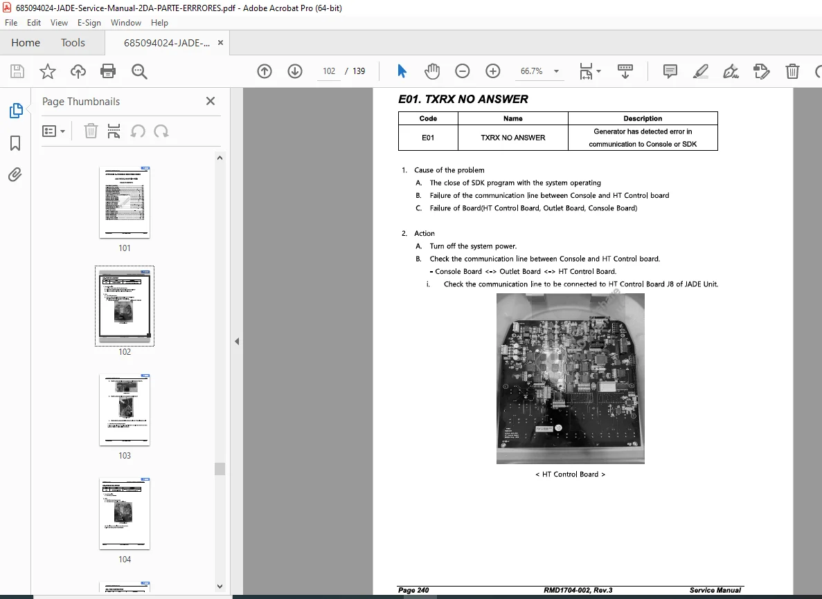
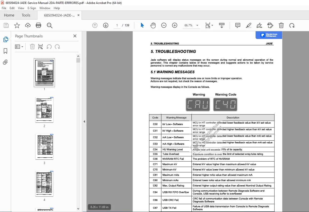
Complete JADE x-ray generator service manual Part 2 focusing on troubleshooting, error codes, and firmware upgrades. This technical service documentation covers warning messages, error diagnostics, and repair procedures for DRGEM JADE diagnostic x-ray generators. Essential troubleshooting guide for biomedical technicians and x-ray service engineers working with medical imaging equipment. Includes comprehensive error code tables and step-by-step firmware upgrade instructions.
Description
JADE X-Ray Generator Service Manual Part 2 – Error Codes & Troubleshooting – PDF DOWNLOAD
DESCRIPTION
This is the JADE X-Ray Generator Service Manual Part 2 – Error Codes & Troubleshooting (November 2023), a comprehensive 139-page technical reference document specifically dedicated to diagnostic error codes and systematic troubleshooting procedures for JADE medical x-ray generator systems. This manual (Part 2 of the complete service documentation) provides essential diagnostic information for qualified biomedical equipment technicians (CBET) and authorized service personnel to diagnose, troubleshoot, and repair JADE x-ray generators used in diagnostic radiology departments, medical imaging centers, hospitals, clinics, and healthcare facilities.
Product Overview
JADE X-Ray Generator Systems:
JADE x-ray generators are professional medical imaging systems designed to provide precise, reliable x-ray energy for diagnostic radiography applications. These high-frequency generator systems deliver consistent radiation output with advanced control features, integrated safety systems, and comprehensive diagnostic capabilities for medical imaging applications including general radiography, fluoroscopy, and specialized diagnostic procedures.
Key Applications:
- Hospital radiology departments
- Outpatient imaging centers
- Urgent care facilities
- Private radiology practices
- Mobile x-ray services
- Veterinary diagnostic imaging
- Industrial radiography (NDT applications)
- Chiropractic clinics
- Orthopedic practices
- Emergency departments
JADE X-Ray Generator Models
Typical Coverage:
- JADE fixed x-ray generators
- JADE mobile x-ray generators
- JADE portable x-ray systems
- JADE fluoroscopy generators
- JADE C-arm generators
- Various power ratings and configurations
Note: This is Part 2 of the complete service manual set, specifically covering error codes and troubleshooting. Part 1 would typically cover installation, specifications, preventive maintenance, and component replacement procedures.
Key Features and Content Areas
Comprehensive Error Code Database:
- Complete error code listings
- Error code descriptions
- Error severity classifications
- Error occurrence conditions
- System response to errors
- Error message displays
Systematic Troubleshooting:
- Fault isolation procedures
- Diagnostic flowcharts
- Step-by-step troubleshooting
- Component testing procedures
- Signal tracing methods
- Measurement procedures
Diagnostic Procedures:
- System diagnostics
- Self-test procedures
- Component diagnostics
- Calibration verification
- Performance testing
- Safety system verification
Repair Protocols:
- Corrective action procedures
- Component replacement guidelines
- Adjustment procedures
- Calibration after repair
- Verification testing
- Documentation requirements
Comprehensive Manual Contents
DOCUMENT INFORMATION:
- Title: JADE Service Manual (Part 2)
- Author: mecat
- Creation Date: November 3, 2023
- Pages: 139 pages
- File Size: 21.7 MB
- Format: Image-based PDF with embedded graphics
- PDF Version: 1.7
TYPICAL CONTENT STRUCTURE
(Based on standard x-ray generator service manual Part 2 organization)
SECTION 1: INTRODUCTION
- Manual purpose and scope
- Safety warnings and precautions
- Qualified personnel requirements
- Service precautions
- Radiation safety
- High voltage warnings
- Electrical safety
- Component handling
- ESD precautions
SECTION 2: ERROR CODE OVERVIEW
Error Code System:
- Error code format and structure
- Error code categories
- Priority levels (critical, warning, information)
- Error code display methods
- Error logging system
- Error history access
Error Classification:
- System Errors – Generator system failures
- Exposure Errors – Exposure-related faults
- Power Errors – Power supply issues
- Communication Errors – Interface problems
- Sensor Errors – Detection system faults
- Safety Errors – Safety interlock faults
- Calibration Errors – Calibration-related issues
SECTION 3: COMPLETE ERROR CODE LISTINGS
Typical Error Code Format:
Error Codes 001-099: System Errors
- E001 – System initialization failure
- E002 – CPU communication error
- E003 – Memory test failure
- E004 – Software version mismatch
- E005 – Configuration data corrupted
- (Additional codes with descriptions)
Error Codes 100-199: Exposure Control Errors
- E101 – Exposure timeout
- E102 – kV regulation failure
- E103 – mA regulation failure
- E104 – Exposure timer malfunction
- E105 – AEC sensor failure
- E106 – Backup timer activated
- (Additional codes with descriptions)
Error Codes 200-299: High Voltage Errors
- E201 – HV transformer overheating
- E202 – kV out of range
- E203 – Filament current error
- E204 – Anode temperature high
- E205 – Tube current error
- E206 – Rectifier failure
- (Additional codes with descriptions)
Error Codes 300-399: Power Supply Errors
- E301 – Input voltage out of range
- E302 – Inverter failure
- E303 – DC bus voltage error
- E304 – Power supply overload
- E305 – Cooling fan failure
- E306 – Thermal protection activated
- (Additional codes with descriptions)
Error Codes 400-499: Communication Errors
- E401 – Console communication lost
- E402 – Detector communication failure
- E403 – RIS/PACS interface error
- E404 – Network timeout
- E405 – Protocol error
- E406 – Data transmission error
- (Additional codes with descriptions)
Error Codes 500-599: Sensor and Detection Errors
- E501 – AEC sensor malfunction
- E502 – Collimator sensor error
- E503 – Grid sensor failure
- E504 – Bucky sensor error
- E505 – Position sensor fault
- E506 – Detector presence error
- (Additional codes with descriptions)
Error Codes 600-699: Safety System Errors
- E601 – Emergency stop activated
- E602 – Door interlock open
- E603 – Collimator position error
- E604 – X-ray warning light failure
- E605 – Safety circuit fault
- E606 – Exposure switch fault
- (Additional codes with descriptions)
Error Codes 700-799: Calibration Errors
- E701 – kV calibration error
- E702 – mA calibration error
- E703 – Time calibration error
- E704 – AEC calibration invalid
- E705 – Detector calibration required
- E706 – Service calibration expired
- (Additional codes with descriptions)
For Each Error Code:
- Error code number
- Error description
- Possible causes
- System response
- Operator actions
- Service technician actions
- Related error codes
- Component locations
SECTION 4: TROUBLESHOOTING PROCEDURES
Systematic Troubleshooting Approach:
General Troubleshooting Guidelines:
- Initial assessment procedures
- Error code interpretation
- System status verification
- Safety checks before servicing
- Required test equipment
- Measurement procedures
- Documentation requirements
Troubleshooting by Symptom:
System Will Not Power On:
- Power source verification
- Circuit breaker checks
- Power supply testing
- Control board inspection
- Fuse verification
- Wiring continuity
- Corrective actions
No Exposure/Exposure Fails:
- Pre-exposure checks
- Exposure switch testing
- Interlock verification
- High voltage circuit checks
- Control signal tracing
- X-ray tube testing
- Fault isolation procedures
Exposure Terminates Early:
- Backup timer investigation
- AEC system testing
- Temperature sensor checks
- Overload protection testing
- Current limiting verification
- Exposure timer testing
Poor Image Quality:
- kV accuracy verification
- mA output testing
- Exposure time verification
- Focal spot testing
- Collimation checks
- Grid alignment
- Detector calibration
Generator Overheating:
- Cooling system inspection
- Fan operation verification
- Thermal sensor testing
- Heat sink inspection
- Duty cycle analysis
- Ambient temperature check
Intermittent Faults:
- Connection inspection
- Thermal cycling tests
- Vibration testing
- Component stress testing
- Error log analysis
- Environmental factors
SECTION 5: COMPONENT TESTING PROCEDURES
High Voltage Circuit Testing:
- kV measurement procedures
- mA measurement procedures
- Waveform analysis
- Transformer testing
- Rectifier testing
- Filter capacitor testing
- Cable integrity testing
Control Circuit Testing:
- Microprocessor testing
- Memory testing
- I/O board testing
- Interface testing
- Signal verification
- Timing verification
Power Supply Testing:
- Input voltage verification
- DC bus voltage testing
- Regulator testing
- Inverter testing
- Load testing
- Ripple measurement
Sensor Testing:
- AEC sensor verification
- Position sensor testing
- Temperature sensor testing
- Current sensors
- Voltage sensors
- Interlock switch testing
Communication Testing:
- Serial interface testing
- Network connectivity
- Protocol verification
- Data transmission testing
- Error rate testing
SECTION 6: DIAGNOSTIC FLOWCHARTS
Visual Troubleshooting Aids:
- Start-to-finish diagnostic paths
- Decision tree structures
- Yes/No decision points
- Measurement specifications
- Test point locations
- Component identification
- Corrective action references
Flowchart Categories:
- Power-up failure flowcharts
- Exposure failure flowcharts
- Error code diagnostic trees
- Safety system flowcharts
- Communication fault trees
- Calibration issue flowcharts
SECTION 7: CORRECTIVE ACTIONS
Repair Procedures:
- Component replacement procedures
- Board replacement procedures
- Cable replacement
- Adjustment procedures
- Recalibration requirements
- Post-repair testing
- Verification procedures
Adjustment Procedures:
- kV calibration adjustment
- mA calibration adjustment
- Timer calibration
- AEC calibration
- Focal spot alignment
- Collimator alignment
Software Updates:
- Software version verification
- Update procedures
- Configuration backup
- Parameter restoration
- Update verification
SECTION 8: PREVENTIVE MAINTENANCE
Preventing Error Conditions:
- Scheduled maintenance tasks
- Cleaning procedures
- Connection inspection
- Cooling system maintenance
- Filter replacement
- Calibration schedules
- Performance testing
SECTION 9: SERVICE TOOLS AND TEST EQUIPMENT
Required Test Equipment:
- Digital multimeter (specifications)
- Oscilloscope (specifications)
- kV meter (non-invasive)
- mA meter
- Timer meter
- Insulation tester (megger)
- Temperature measurement
- Service software/laptop
Special Tools:
- Manufacturer-specific tools
- Calibration fixtures
- Test jigs
- Adapter cables
- Service keys/passwords
SECTION 10: SAFETY TESTING
Post-Repair Safety Verification:
- Electrical safety testing
- Leakage current measurement
- Ground resistance verification
- Radiation safety testing
- Interlock verification
- Warning system testing
- Documentation requirements
SECTION 11: SERVICE DOCUMENTATION
Record Keeping:
- Service report templates
- Error log documentation
- Repair documentation
- Calibration records
- Parts replacement records
- Customer communication
- Warranty documentation
Who Needs This Manual?
This JADE X-Ray Generator Service Manual Part 2 is essential for:
- Certified biomedical equipment technicians (CBET)
- Hospital clinical engineering departments
- Medical equipment service companies
- Authorized JADE service centers
- Radiology equipment specialists
- X-ray system service technicians
- Medical physics technicians
- Anyone performing authorized service on JADE generators
Prerequisites:
✓ JADE-specific service training
✓ Medical x-ray equipment experience
✓ High voltage safety training
✓ Radiation safety certification
✓ Electronic troubleshooting skills
✓ IEC 60601-1 medical electrical safety knowledge
✓ Understanding of x-ray generator principles
✓ ESD handling procedures
✓ Service Manual Part 1 (for complete system understanding)
FILE DETAILS
| Detail | Specification |
|---|---|
| Manual Title | JADE X-Ray Generator Service Manual Part 2 – Error Codes & Troubleshooting |
| Coverage | Error codes, troubleshooting, diagnostics, repair protocols |
| Author | mecat |
| Creation Date | November 3, 2023 |
| Last Modified | November 3, 2023 |
| Pages | 139 pages |
| PDF Quality | Image-based PDF with embedded graphics and diagrams |
| File Size | 21.7 MB |
| Page Size | A4 (595 x 842 pts) |
| Language | English (assumed) |
| Creator | PScript5.dll Version 5.2.2 |
| PDF Version | 1.7 |
| Manual Type | Part 2 of complete service manual set |