JCB 532H, 537H Loadalls Service Manual (Supplement) – 9803/3641 – PDF DOWNLOAD
Original price was: $89.00.$28.95Current price is: $28.95.
JCB 532H, 537H Loadalls Service Manual (Supplement) – 9803/3641
Description
JCB 532H, 537H Loadalls Service Manual (Supplement) – 9803/3641
APPLICABLE MODELS :
This manual is a supplement to the Loadall Service Manual.
The information covers :
JCB Loadall 532H machine from S/N: 770970 and
JCB Loadall 537H machine from S/N: 773560, unless specified otherwise
FILE DETAILS:
JCB 532H, 537H Loadalls Service Manual (Supplement) – 9803/3641
File Format : PDF
Language : English
Printable : Yes
Searchable : Yes
Bookmarked : Yes
P/N : 9803/3641
Total Pages : 126
DESCRIPTION:
JCB 532H, 537H Loadalls Service Manual (Supplement) – 9803/3641
This manual is a supplement to the Loadall Service Manual. The information covers the 532H machine from serial number 770970 and the 537H machine from serial number 773560, unless specified otherwise. Note: Only those areas of the machines which are different from the non-hydrostatic version are dealt with here. For all other aspects refer to the Service Manual. Unless specified otherwise, all references to ‘Service Manual’ in this supplement are to be taken as meaning the appropriate publication listed below.
9803/3660 Loadall Service Manual (English)
9803/3661 Loadall Service Manual (French)
9803/3662 Loadall Service Manual (German).
TABLE OF CONTENTS:
JCB 532H, 537H Loadalls Service Manual (Supplement) – 9803/3641
Section 1 General Information
Introduction
Care and Safety 1 – 1
Service Tools 1 – 2
Section 2 Care and Safety
Operating Safety 1 – 1
Maintenance Safety 1 – 1
Section 3 Routine Maintenance
Introduction
Fluids, Lubricants, Capacities and Specifications 1 – 1
Service Schedules 2 – 1
Towing a Machine 4 – 1
Checking the Drop Box Oil Level 5 – 1
Changing the Transmission Charge Filter 6 – 1
Testing the Parking Brake 7 – 1
Section C Electrics
Introduction 1 – 1
Fuses and relays
Fuse Identification 1 – 2
Relay Identification 1 – 3
Transmission Controller
Diagnostic LED’s 2 – 1
Schematic Diagrams 4 – 1 to 4 – 8
Overall Contents
9803/3641
ii
Issue 2*
Section E Hydraulics
Technical Data 1 – 1
Hydraulic Contamination 2 – 1
Fault Finding 3 – 1
Schematic Diagrams and Circuit Descriptions
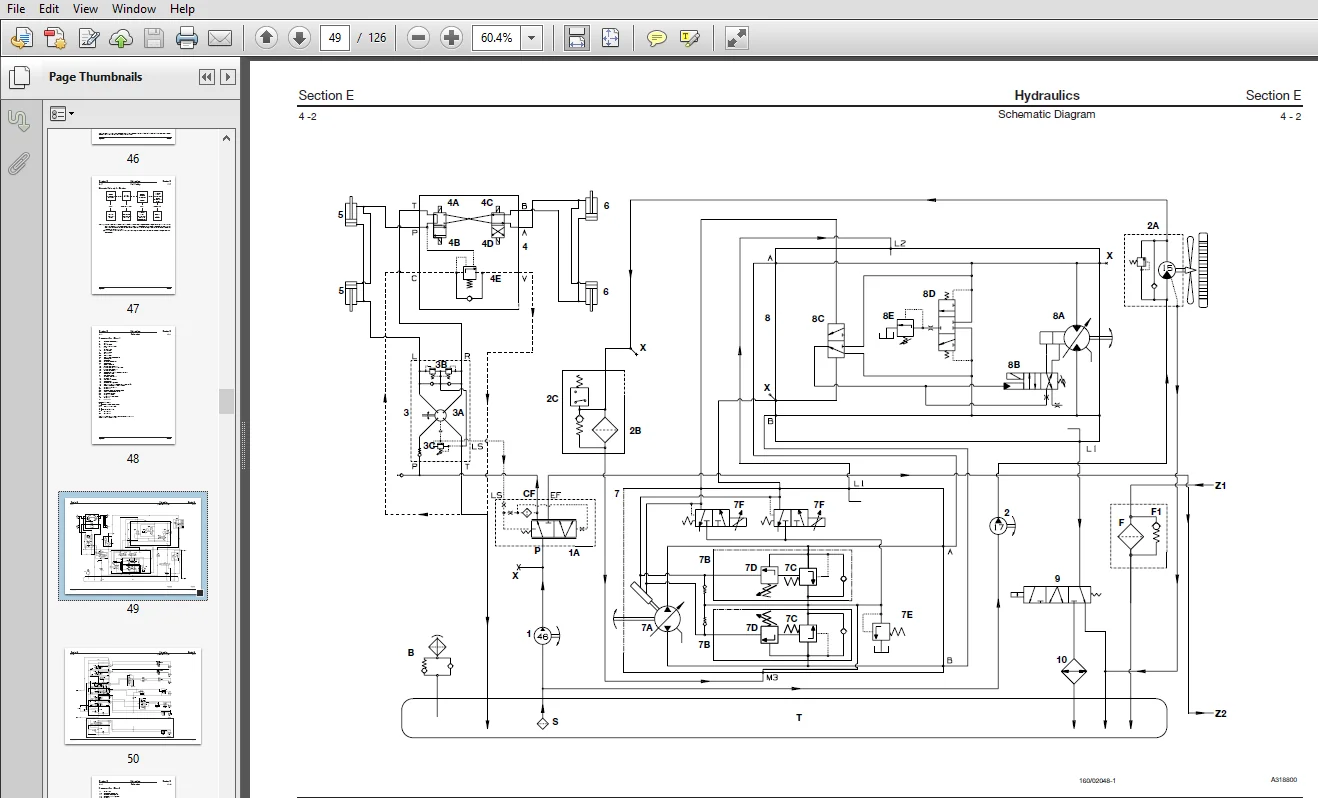
Schematic Diagrams 4 – 1
Circuit Descriptions
Drive Pump 4 – 5
Drive Motor 4 – 6
Engine/Drive Pump Coupling 5 – 1
Drive Pump
Removal and Replacement 6 – 1
Minor Repairs
Location of Components 6 – 3
Shaft Seal 6 – 4
Multi-Function Valves 6 – 5
Charge Pressure Relief Valve 6 – 5
Coupling Removal and Replacement 6 – 6
Servo Piston Cover Seals Renewal 6 – 7
Control Valve 6 – 8
Speed Sensor Removal and Replacement 6 – 9
Pump Cover 6 – 10
Servo Control Valve 6 – 10
Drive Motor/Drop Box Assembly
Removal and Replacement 7 – 1
Minor Repairs
Location of Components 7 – 3
Shaft Seal 7 – 4
Loop Flushing Valve 7 – 5
Charge Pressure Relief Valve 7 – 5
Multi-Function Block/Pressure Compensator Valve 7 – 6
Fan Pump
Removal and Replacement 8 – 1
Dismantling and Assembly 8 – 2
Fan Motor
Removal and Replacement 9 – 1
Dismantling and Assembly 9 – 2
Main Service Pump
Removal and Replacement 11 – 1
Dismantling and Assembly 11 – 2
iii
Overall Contents
9803/3641
iii
Issue 2*
Section E Hydraulics (continued)
Priority Valve
Description and Operation 12 – 1
Removal and Replacement
To Machine Serial Number 775548 12 – 2
Dismantling and Assembly
To Machine Serial Number 775548 12 – 3
Removal and Replacement
From Machine Serial Number 775549 12 – 4
Dismantling and Assembly
From Machine Serial Number 775549 12 – 5
Transmission Oil Cooler Bypass Valve
Removal and Replacement 13 – 1
Start-up procedure 15 – 1
Section F Transmission
Introduction 1 – 1
Technical Data 1 – 1
Description and Operation
Introduction 2 – 1
Drive Circuit 2 – 2
Fan (Charge) Pump and Fan Motor Circuit 2 – 3
Brake Pressure Defeat Valve 2 – 3
Case Drain Circuit 2 – 4
Oil Cooling Circuit 2 – 5
Test Points 2 – 6
Sensors 2 – 7
Drop Box
Removal and Replacement 4 – 1
Dismantling and Assembly 5 – 1
Propshafts
Removal and Replacement 6 – 1
Section G Brakes
Introduction 1 – 1
Technical Data 1 – 1
Parking Brake
Adjustment 2 – 1
Section H Steering
Introduction 1 – 1
Technical Data 1 – 1
iv
Overall Contents
9803/3641
iv
Issue 1
Section K Engine
Introduction 1 – 1
Technical Data 1 – 1
Engine Removal and Replacement 2 – 1
Renewing the Coupling 2 – 5
Drive Flange Replacement 2 – 6
Engine Mounting Bracket And Bushes 2 – 6
Machine Start-up Procedure 2 – 7
JCB 532H, 537H LOADALLS SERVICE MANUAL (SUPPLEMENT) – 9803/3641 – PDF DOWNLOAD:
IMAGES PREVIEW OF THE MANUAL:
PLEASE NOTE:
- This is the SAME exact manual used by your dealers to fix your vehicle.
- The same can be yours in the next 2-3 mins as you will be directed to the download page immediately after paying for the manual.
- Any queries / doubts regarding your purchase, please feel free to contact [email protected]