JLG 1200SJP 1350SJP Illustrated Parts Manual 3121208 – PDF DOWNLOAD
$25.95
JLG 1200SJP 1350SJP Illustrated Parts Manual 3121208 – PDF DOWNLOAD
Description
JLG 1200SJP 1350SJP Illustrated Parts Manual 3121208 – PDF DOWNLOAD
FILE DETAILS:
JLG 1200SJP 1350SJP Illustrated Parts Manual 3121208 – PDF DOWNLOAD
Language : English
Pages : 454
Downloadable : Yes
File Type : PDF
IMAGES PREVIEW OF THE MANUAL:
TABLE OF CONTENTS:
JLG 1200SJP 1350SJP Illustrated Parts Manual 3121208 – PDF DOWNLOAD
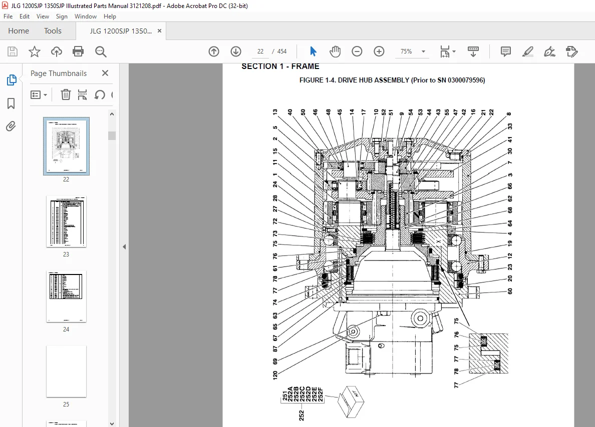
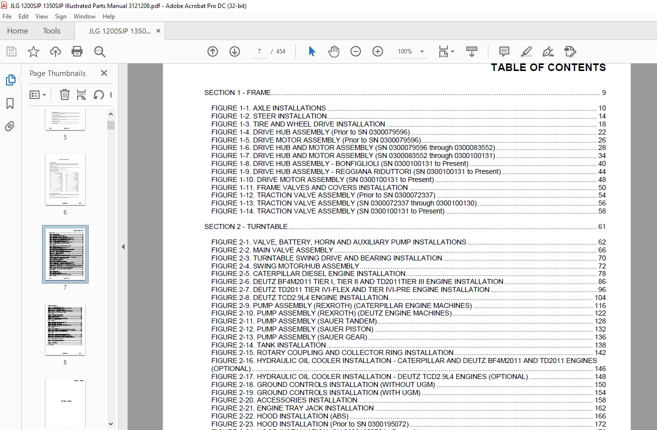
SECTION 1 – FRAME 9
FIGURE 1-1 AXLE INSTALLATIONS 10
FIGURE 1-2 STEER INSTALLATION 14
FIGURE 1-3 TIRE AND WHEEL DRIVE INSTALLATION 18
FIGURE 1-4 DRIVE HUB ASSEMBLY (Prior to SN 0300079596) 22
FIGURE 1-5 DRIVE MOTOR ASSEMBLY (Prior to SN 0300079596) 26
FIGURE 1-6 DRIVE HUB AND MOTOR ASSEMBLY (SN 0300079596 through 0300083552) 28
FIGURE 1-7 DRIVE HUB AND MOTOR ASSEMBLY (SN 0300083552 through 0300100131) 34
FIGURE 1-8 DRIVE HUB ASSEMBLY – BONFIGLIOLI (SN 0300100131 to Present) 40
FIGURE 1-9 DRIVE HUB ASSEMBLY – REGGIANA RIDUTTORI (SN 0300100131 to Present) 44
FIGURE 1-10 DRIVE MOTOR ASSEMBLY (SN 0300100131 to Present) 48
FIGURE 1-11 FRAME VALVES AND COVERS INSTALLATION 50
FIGURE 1-12 TRACTION VALVE ASSEMBLY (Prior to SN 0300072337) 54
FIGURE 1-13 TRACTION VALVE ASSEMBLY (SN 0300072337 through 0300100130) 56
FIGURE 1-14 TRACTION VALVE ASSEMBLY (SN 0300100131 to Present) 58
SECTION 2 – TURNTABLE 61
FIGURE 2-1 VALVE, BATTERY, HORN AND AUXILIARY PUMP INSTALLATIONS 62
FIGURE 2-2 MAIN VALVE ASSEMBLY 66
FIGURE 2-3 TURNTABLE SWING DRIVE AND BEARING INSTALLATION 70
FIGURE 2-4 SWING MOTOR/HUB ASSEMBLY 72
FIGURE 2-5 CATERPILLAR DIESEL ENGINE INSTALLATION 78
FIGURE 2-6 DEUTZ BF4M2011 TIER I, TIER II AND TD2011TIER III ENGINE INSTALLATION 86
FIGURE 2-7 DEUTZ TD2011 TIER IVI-FLEX AND TIER IVI-PRE ENGINE INSTALLATION 96
FIGURE 2-8 DEUTZ TCD2 9L4 ENGINE INSTALLATION 104
FIGURE 2-9 PUMP ASSEMBLY (REXROTH) (CATERPILLAR ENGINE MACHINES) 116
FIGURE 2-10 PUMP ASSEMBLY (REXROTH) (DEUTZ ENGINE MACHINES) 122
FIGURE 2-11 PUMP ASSEMBLY (SAUER TANDEM) 128
FIGURE 2-12 PUMP ASSEMBLY (SAUER PISTON) 132
FIGURE 2-13 PUMP ASSEMBLY (SAUER GEAR) 136
FIGURE 2-14 TANK INSTALLATION 138
FIGURE 2-15 ROTARY COUPLING AND COLLECTOR RING INSTALLATION 142
FIGURE 2-16 HYDRAULIC OIL COOLER INSTALLATION – CATERPILLAR AND DEUTZ BF4M2011 AND TD2011 ENGINES (OPTIONAL) 146
FIGURE 2-17 HYDRAULIC OIL COOLER INSTALLATION – DEUTZ TCD2 9L4 ENGINES (OPTIONAL) 148
FIGURE 2-18 GROUND CONTROLS INSTALLATION (WITHOUT UGM) 150
FIGURE 2-19 GROUND CONTROLS INSTALLATION (WITH UGM) 154
FIGURE 2-20 ACCESSORIES INSTALLATION 158
FIGURE 2-21 ENGINE TRAY JACK INSTALLATION 162
FIGURE 2-22 HOOD INSTALLATION (ABS) 166
FIGURE 2-23 HOOD INSTALLATION (Prior to SN 0300195072) 172
FIGURE 2-24 HOOD INSTALLATION (SN 0300195072 to Present) 178
FIGURE 2-25 2500W GENERATOR INSTALLATION – CATERPILLAR MACHINES (OPTIONAL) 182
FIGURE 2-26 2500W GENERATOR INSTALLATION – DEUTZ MACHINES (OPTIONAL) 186
FIGURE 2-27 4000W GENERATOR INSTALLATION – DEUTZ MACHINES 190
FIGURE 2-28 7500W SKYPOWER GENERATOR INSTALLATION – CATERPILLAR MACHINES 194
FIGURE 2-29 7500W SKYPOWER GENERATOR INSTALLATION – DEUTZ MACHINES (HYDRAULICALLY DRIVEN) (Prior to SN 0300080338) 200
FIGURE 2-30 7500W SKYPOWER GENERATOR INSTALLATION – DEUTZ MACHINES (BELT DRIVEN) (SN 0300080338 to Present) 206
FIGURE 2-31 CLEARSKY TELEMATICS INSTALLATION (WITHOUT UGM) (OPTIONAL) 214
FIGURE 2-32 CLEARSKY TELEMATICS INSTALLATION (WITH UGM) (OPTIONAL) 218
SECTION 3 – BOOM 221
FIGURE 3-1 BOOM INSTALLATION 222
FIGURE 3-2 BOOM ASSEMBLY 224
FIGURE 3-3 ACTUATOR ASSEMBLIES 232
FIGURE 3-4 POWER TRACK INSTALLATION 236
FIGURE 3-5 BOOM SENSORS AND SWITCHES INSTALLATION 242
FIGURE 3-6 PLATFORM SUPPORT AND CONTROL VALVES INSTALLATIONS 246
SECTION 4 – PLATFORM 249
FIGURE 4-1 PLATFORM COMPONENTS INSTALLATION 250
FIGURE 4-2 PLATFORM COMPONENTS INSTALLATION (FALL ARREST PLATFORM) 254
FIGURE 4-3 PLATFORM CONSOLE ASSEMBLY 256
FIGURE 4-4 CONTROLLER ASSEMBLY (LIFT AND SWING) 262
FIGURE 4-5 CONTROLLER ASSEMBLY (LIFT AND SWING) (SN 0300188514 to Present) 266
FIGURE 4-6 CONTROLLER ASSEMBLY (DRIVE AND STEER) 270
FIGURE 4-7 CONTROLLER ASSEMBLY (DRIVE AND STEER) (SN 0300188514 to Present) 274
FIGURE 4-8 SOFT TOUCH SYSTEM INSTALLATION (OPTIONAL) 276
SECTION 5 – CYLINDER 279
FIGURE 5-1 AXLE EXTENSION CYLINDER ASSEMBLY 280
FIGURE 5-2 AXLE LOCKOUT CYLINDER ASSEMBLY 282
FIGURE 5-3 PLATFORM LEVEL CYLINDER ASSEMBLY 284
FIGURE 5-4 LIFT CYLINDER ASSEMBLY 286
FIGURE 5-5 JIB CYLINDER ASSEMBLY 288
FIGURE 5-6 STEER CYLINDER ASSEMBLY (Prior to SN 0300073367) 290
FIGURE 5-7 STEER CYLINDER ASSEMBLY (SN 0300073367 to Present) 292
FIGURE 5-8 TELESCOPE CYLINDER ASSEMBLY 294
SECTION 6 – HYDRAULIC 297
FIGURE 6-1 HYDRAULIC DIAGRAM – DRIVE (Prior to SN 0300100131) 298
FIGURE 6-2 HYDRAULIC DIAGRAM – OSCILLATING AXLE 302
FIGURE 6-3 HYDRAULIC DIAGRAM – STEER 304
FIGURE 6-4 HYDRAULIC DIAGRAM – TURNTABLE 306
FIGURE 6-5 HYDRAULIC DIAGRAM – BOOM (Prior to SN 0300119707) 310
FIGURE 6-6 HYDRAULIC DIAGRAM – 7500W GENERATOR (Prior to SN 0300080338) 314
FIGURE 6-7 HYDRAULIC DIAGRAM LIST 316
SECTION 7 – ELECTRICAL 319
FIGURE 7-1 ELECTRICAL DIAGRAM LIST 320
FIGURE 7-2 HARNESS COMPONENTS INSTALLATION (WITHOUT UGM) (Prior to SN 0300087579) 322
FIGURE 7-3 HARNESS COMPONENTS INSTALLATION (WITHOUT UGM) (SN 0300087579 to Present) 338
FIGURE 7-4 HARNESS COMPONENTS INSTALLATION (WITH UGM) 358
FIGURE 7-5 HARNESS COMPONENTS INSTALLATION (WITH UGM) 378
SECTION 8 – DECALS 397
FIGURE 8-1 DECAL INSTALLATION (ANSI SPEC) (Prior to SN 0300089981) 398
FIGURE 8-2 DECAL INSTALLATION (ANSI SPEC) (SN 0300089981 to Present) 402
FIGURE 8-3 DECAL INSTALLATION (ANSI EXPORT SPECS) (Prior to SN 0300089981) 406
FIGURE 8-4 DECAL INSTALLATION (ANSI EXPORT SPECS) (SN 0300089981 to Present) 410
FIGURE 8-5 DECAL INSTALLATION (AUSTRALIAN AND CE SPECS) (Prior to SN 0300089981) 416
FIGURE 8-6 DECAL INSTALLATION (AUSTRALIAN AND CE SPECS) (SN 0300089981 to Present) 422
SECTION 9 – RECOMMENDED SERVICE PARTS STOCK 425
FIGURE 9-1 MODEL 1200SJP/1350SJP STANDARD PARTS 426
FIGURE 9-2 MODEL 1200SJP/1350SJP VARIABLE PARTS 428
SECTION 10 – SPECIAL OPTIONS 429
FIGURE 10-1 SPECIAL OPTIONS 430
PART NUMBER INDEX 435
Questions? Email us: [email protected]
PLEASE NOTE:
- This is the SAME MANUAL used by the dealerships to diagnose your vehicle
- No waiting for couriers / posts as this is a PDF manual and you can download it within 2 minutes time once you make the payment.
- Your payment is all safe and the delivery of the manual is INSTANT – You will be taken to the DOWNLOAD PAGE.
- So have no hesitations whatsoever and write to us about any queries you may have : heydownloadss @gmail.com
S.M