JLG 1200SJP 1350SJP Service & Maintenance Manual 3121142 – PDF DOWNLOAD
$30.95
JLG 1200SJP 1350SJP Service & Maintenance Manual 3121142 – PDF DOWNLOAD
Description
JLG 1200SJP 1350SJP Service & Maintenance Manual 3121142 – PDF DOWNLOAD
FILE DETAILS:
JLG 1200SJP 1350SJP Service & Maintenance Manual 3121142 – PDF DOWNLOAD
Language : English
Pages : 554
Downloadable : Yes
File Type : PDF
DESCRIPTION:
JLG 1200SJP 1350SJP Service & Maintenance Manual 3121142 – PDF DOWNLOAD
GENERAL
This section contains the general safety precautions which must be observed during maintenance of the aerial platform. It is of utmost importance that maintenance personnel pay strict attention to these warnings and precautions to avoid possible injury to themselves or others, or damage to the equipment. A maintenance program must be followed to ensure that the machine is safe to operate.
- The specific precautions to be observed during maintenance are inserted at the appropriate point in the manual. These precautions are, for the most part, those that apply when servicing hydraulic and larger machine component parts.
- Your safety, and that of others, is the first consideration when engaging in the maintenance of equipment. Always be conscious of weight. Never attempt to move heavy parts without the aid of a mechanical device.
- Do not allow heavy objects to rest in an unstable position. When raising a portion of the equipment, ensure that adequate support is provided.
B HYDRAULIC SYSTEM SAFETY
It should be noted that the machines hydraulic systems operate at extremely high potentially dangerous pressures. Every effort should be made to relieve any system pressure prior to disconnecting or removing any portion of the system. Relieve system pressure by cycling the applicable control several times with the engine stopped and ignition on, to direct any line pressure back into the reservoir. Pressure feed lines to system components can then be disconnected with minimal fluid loss.
MAINTENANCE
- NO SMOKING IS MANDATORY. NEVER REFUEL DURING ELECTRICAL STORMS. ENSURE THAT FUEL CAP IS CLOSED AND SECURE AT ALL OTHER TIMES.
- REMOVE ALL RINGS, WATCHES AND JEWELRY WHEN PERFORMING ANY MAINTENANCE.
- DO NOT WEAR LONG HAIR UNRESTRAINED, OR LOOSE-FITTING CLOTHING AND NECKTIES WHICH ARE APT TO BECOME CAUGHT ON OR ENTANGLED IN EQUIPMENT.
- OBSERVE AND OBEY ALL WARNINGS AND CAUTIONS ON MACHINE AND IN SERVICEMANUAL.
- KEEP OIL, GREASE, WATER, ETC. WIPED FROM STANDING SURFACES AND HAND HOLDS.
- USE CAUTION WHEN CHECKING A HOT, PRESSURIZED COOLANT SYSTEM.
- NEVER WORK UNDER AN ELEVATED BOOM UNTIL BOOM HAS BEEN SAFELY RESTRAINED FROM ANY MOVEMENT BY BLOCKING OR OVERHEAD SLING, OR BOOM SAFETY PROP HAS BEEN ENGAGED.
- BEFORE MAKING ADJUSTMENTS, LUBRICATING OR PERFORMING ANY OTHER MAINTENANCE, SHUT OFF ALL POWER CONTROLS.
- BATTERY SHOULD ALWAYS BE DISCONNECTEDDURING REPLACEMENT OF ELECTRICAL COMPONENTS
- KEEP ALL SUPPORT EQUIPMENT AND ATTACHMENTS STOWED IN THEIR PROPER PLACE.
- USE ONLY APPROVED, NONFLAMMABLE CLEANING SOLVENTS.
IMAGES PREVIEW OF THE MANUAL:
TABLE OF CONTENTS:
JLG 1200SJP 1350SJP Service & Maintenance Manual 3121142 – PDF DOWNLOAD
Section A INTRODUCTION – MAINTENANCE SAFETY PRECAUTIONS 3
A General 3
B Hydraulic System Safety 3
C Maintenance 3
Section 1 SPECIFICATIONS 21
1 1 Capacities 21
1 2 Tires 21
1 3 Engine Data 21
Deutz Prior to S/N 0300127698 21
Deutz S/N 0300127698 to Present 21
Caterpillar 21
1 4 Specifications and Performance Data 22
Reach Specifications 22
Dimensional Data 22
Chassis 22
1 5 Torque Requirements 23
1 6 Hydraulic Oil 23
1 7 Major Component Weights 25
1 8 Pressure Settings 25
1 9 Lubrication and Operator Maintenance 27
Section 2 GENERAL 37
2 1 Machine Preparation, Inspection, and Maintenance 37
General 37
Preparation, Inspection, and Maintenance 37
Pre-Start Inspection 37
Pre-Delivery Inspection and Frequent Inspection 37
Annual Machine Inspection 37
Preventative Maintenance 37
2 2 Service and Guidelines 38
General 38
Safety and Workmanship 38
Cleanliness 38
Components Removal and Installation 38
Component Disassembly and Reassembly 39
Pressure-Fit Parts 39
Bearings 39
Gaskets 39
Bolt Usage and Torque Application 39
Hydraulic Lines and Electrical Wiring 39
Hydraulic System 39
Lubrication 39
Battery 39
Lubrication and Servicing 39
2 3 Lubrication and Information 39
Hydraulic System 39
Hydraulic Oil 40
Changing Hydraulic Oil 40
Lubrication Specifications 40
2 4 Cylinder Drift Test 40
Platform Drift 40
Cylinder Drift 41
2 5 Pins and Composite Bearing Repair Guidelines 41
2 6 Welding on JLG Equipment 41
Do the Following When Welding on JLG Equipment 41
Do NOT Do the Following When Welding on JLG Equipment 41
Section 3 CHASSIS & TURNTABLE 47
3 1 Tires & Wheels 47
Tire Inflation 47
Tire Damage 47
Wheel and Tire Replacement 47
Wheel Installation 47
3 2 Extending Axles 48
3 3 Axle Limit Switch Adjustment Procedure 48
3 4 Drive System 49
3 5 Steering Control System 49
3 6 Drive/Steering Speed Control 50
3 7 Traction Control System 50
3 8 Drive Orientation System 50
3 9 Oscillating Axle System 60
3 10 Oscillating Axle Bleeding Procedure and Lockout Test 60
Lockout Cylinder Bleeding 60
Oscillating Axle Lockout Test 61
3 11 Drive Hub (Prior to S/N 100131) 62
Disassembly 62
Disassembly of Cover 62
Disassembly of the First Stage Planetary Assembly (7) 62
Disassembly of Second Stage Planet Gears (1) 62
Assembly of First Stage Planetary Assembly (7) 63
Assembly of End Cover Unit (8) 63
Final Assembly 63
Initial Start-up And After Repairs 63
Oil Change Interval-Gear Drive 63
3 12 Drive Hub – Bonfiglioli (S/N 100128 to Present) 66
Product Identification 66
Hydraulic Motor Installation 66
Installation of the Wheel Drive on the Machine 66
Start Up and Running In 66
General Information 67
Connecting the Brake 67
Filling-up the Gearbox with Lubricating Oil 67
Gearbox Disengagement 69
Maintenance Information 71
Changing the Lubricating oil 71
Troubleshooting 72
Disassembly Information 72
Disassembly Procedure 72
Inspection of Parts 80
Assembly 81
Final Test and Reinstallation 91
3 13 Drive Hub – Reggiana Riduttori (S/N 134389 to Present) 96
Symbol Nomenclature 96
Tools 96
Disassembly 101
Assembly 105
3 14 Swing Drive 111
Roll and Leak Testing 111
Tightening and Torquing Bolts 111
Motor Control Valve Disassembly 112
Motor and Brake Disassembly 113
Main Disassembly 114
Hub-Shaft Disassembly 115
Carrier Disassembly 116
Hub-Shaft Sub-Assembly 117
Carrier Sub-Assembly 118
Main Assembly 120
Motor and Brake Assembly 122
Motor Control Valve Assembly 123
3 15 Swing Brake 124
Pre-Installation Checks 124
Installation 125
Maintenance 125
Disassembly 125
Examination 125
Assembly 125
3 16 Swing Motor 128
Disassembly and inspection 128
Assembly 135
One Piece Stator Construction 142
3 17 Procedure For Setting Gear Backlash 143
3 18 Swing Drive Lubrication 144
3 19 Swing Bearing 145
Turntable Bearing Mounting Bolt Condition Check 145
Wear Tolerance 148
Swing Bearing Removal 148
Swing Bearing Installation 150
Swing Bearing Torque Values 151
3 20 Swing Speed Proportioning 152
3 21 Chassis Tilt Indicator System 152
3 22 Rotary Coupling 153
3 23 Generator 157
Every 250 hours 157
Every 500 hours 157
Overload Protection 158
Inspecting Brushes, Replacing Brushes, and Cleaning Slip Rings 158
3 24 Auxiliary Power System 160
3 25 Cold Weather Package 162
3 26 Engine 162
Glow Plugs 162
Checking Oil Level 162
Changing Engine Oil 162
Changing the Oil Filter 163
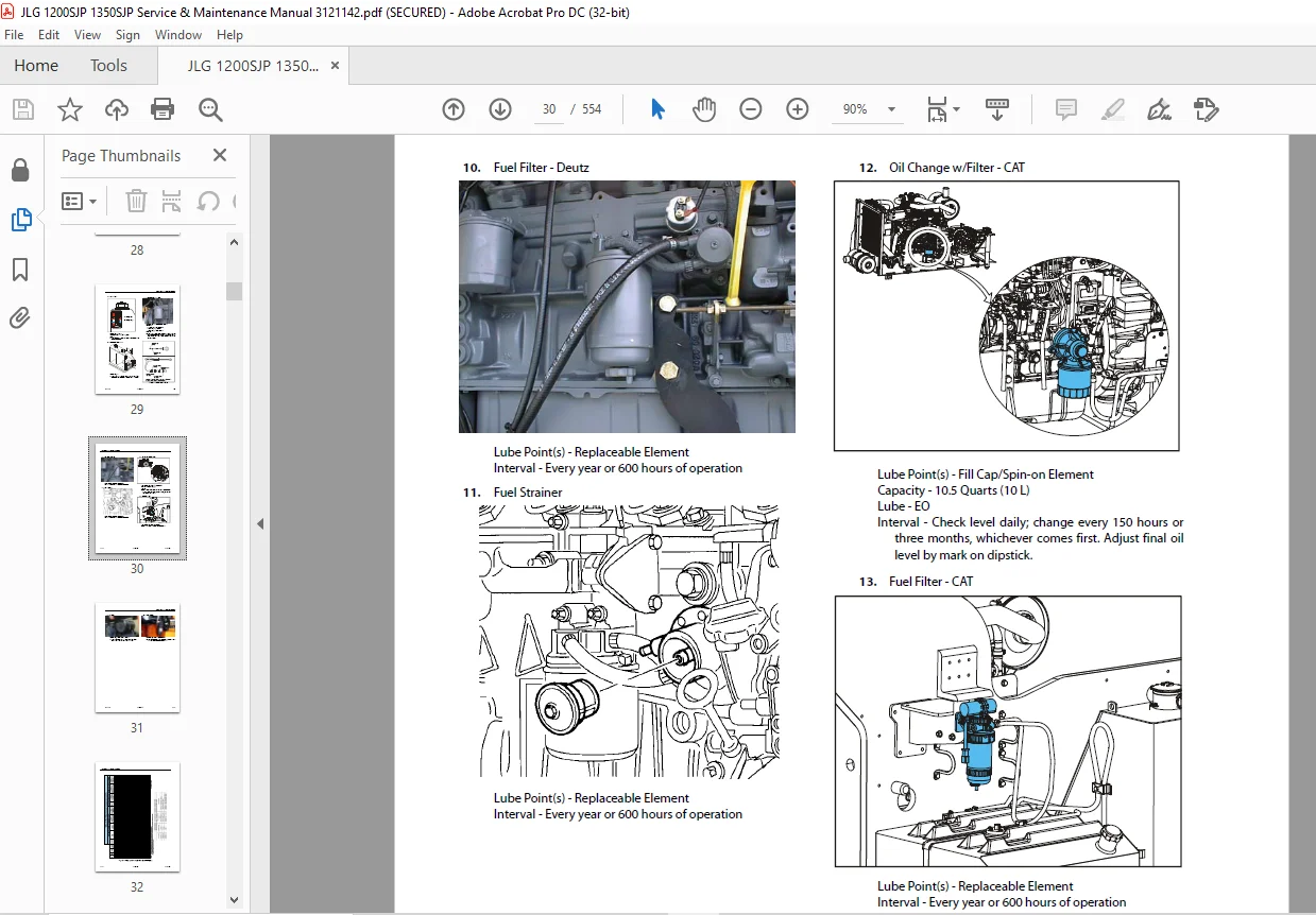
Replacing the Fuel Filter 164
Cleaning the Fuel Strainer 164
3 27 Deutz EMR 2 (S/N 87579 to Present) 165
3 28 Bio Fuel in Deutz Engines 178
General 178
Bio Fuel 178
Biological Contamination In Fuels 179
3 29 CAT DGC DIAGNOSTIC SUPPORT AND TROUBLE CODE DEFINITIONS 180
List of Abbreviations in this Section 182
Diagnostic Trouble Codes 184
CAN 184
MIL Output 184
DTC 116- ECT Higher Than Expected Stage 1 185
DTC 117- ECT/CHT Low Voltage 186
DTC 118- ECT/CHT High Voltage 188
DTC 122- TPS1 Signal Voltage Low 190
DTC 123- TPS1 Signal Voltage High 192
DTC 217- ECT Higher Than Expected 2 194
DTC 219- RPM Higher Than Max Allowed Governed Speed 195
DTC 336- Crank Signal Input Noise 196
DTC 337- Loss of Crank Input Signal 198
DTC 521- Oil Pressure Sender/Switch High Pressure 199
DTC 524- Oil Pressure Low 200
DTC 562- Battery Voltage (VBat) Low 202
DTC 563- Battery Voltage (VBat) High 204
DTC 601- Microprocessor Failure – FLASH 206
DTC 604- Microprocessor Failure – RAM 208
DTC 606- Microprocessor Failure – COP 210
DTC 642- 5 Volt External Low Voltage 212
DTC 643- 5 Volt External High Voltage 213
DTC 1612- Microprocessor Failure – RTI 1 214
DTC 1613- Microprocessor Failure – RTI 2 215
DTC 1614- Microprocessor Failure – RTI 3 217
DTC 1615- Microprocessor Failure – A/D 219
DTC 1616- Microprocessor Failure – interrupt 221
DTC 1625- CAN J1939 Shutdown Request 223
DTC 1626- CAN J1939 Transmit (Tx) Fault 224
DTC 1627- CAN J1939 Receive (Rx) Fault 225
DTC 1628- CAN Address Conflict Failure 226
DTC 1629- J1939 TSC1 Message Reciept Loss 228
DTC 1652- TPS1 Loss of Communications 229
DTC 2111- Unable to Reach Lower TPS 230
DTC 2112- Unable to Reach Higher TPS 232
DTC 9999- Throttle Actuator Failsafe Spring Failure 233
DTC to SPN/FMI Table 234
Section 4 BOOM & PLATFORM 235
4 1 Boom Systems 235
Broken Cable Indicator System 235
Platform Control Enable System 235
Transport Position Sensing System 235
Beyond Transport – Drive Speed Cutback System 235
Drive/Steer – Boom Function Interlock System (CE ONLY) 236
Jib Stow System 236
Envelope Tracking System 236
Moment Control System 237
Boom Control System (BCS) Functional Check (Push to Test) System 237
Controlled Arc System 237
Controlled Boom Angle System 238
Envelope Tracking 238
Slow Down System 238
Dual Capacity System 239
Electronic Platform Leveling 239
Boom Control Select 240
4 2 Boom Removal, Disassembly/Assembly, & Cable Replacement 241
Removal 241
Disassembly 250
Assembly 261
4 3 Boom Lubrication Application 277
4 4 Boom Shimming Procedure 277
4 5 Jib Rotator Orientation 278
4 6 Jib Lift End of Stroke Dampening 278
4 7 Load Sensing Pin Removal and Installation 278
4 8 Powertrack Maintenance 287
One Piece Bracket Maintenance 287
Two Piece Bracket Maintenance 289
Snap Rings and Screws 290
4 9 Hose Routing Procedure 298
4 10 Wire Rope 298
Inspection 298
Three Month Inspection 298
Eight Year Inspection 298
Replacement Criteria 298
4 11 Wire Rope Tensioning Adjustment 299
Boom Section Re-Positioning 299
Wire Rope Tensioning Procedure 301
4 12 Broken Boom Cable Proximity Switch 308
Adjusting the Proximity Switch 308
4 13 Electronic Platform Leveling 308
Description 308
Normal Operation 309
4 14 Rotary Actuator 310
Theory of Operation 310
Required Tools 310
Disassembly 313
Inspection 317
Assembly 317
Installing Counterbalance Valve 322
Testing the Actuator 322
Bleeding After Installation 322
Section 5 HYDRAULICS 325
5 1 Lubricating O-Rings in the Hydraulic System 325
Cup and Brush 325
Dip Method 326
Spray Method 326
Brush-on Method 326
5 2 Cylinder Repair 327
Disassembly 327
Cleaning and Inspection 336
Assembly 338
5 3 Hydraulic Tank 349
5 4 Pressure Setting Procedure 349
Set Up of the Function Pump 349
Adjustments made at the Main Valve Bank 350
Adjustments Made at the Frame Valve Bank 351
Adjustments Made at the Platform Valve Bank 355
5 5 Drive Pumps 356
Troubleshooting Procedure 356
Charge Pressure Relief Valve Adjustment 359
Mechanical Centering of Pump 360
Hydraulic Centering of Control Modules 360
High Pressure Relief Valve Adjustments 361
Removal and inspection of charge pump 361
Routine Maintenance 362
Removal and Installation of Shaft Seal 364
5 6 Function Pump 365
Spare Parts 365
Sealing the Drive Shaft 366
Disassembly and Assembly of the Complete Unit 367
Assembly 370
Adjustments 371
Tightening Torques 371
Pump Control Disassembly For Cleaning 373
5 7 Drive & Function Pump Start Up Procedures 375
Start-Up Procedure 375
Section 6 JLG CONTROL SYSTEM 377
6 1 Introduction 377
6 2 CANbus Communications 378
6 3 Calibration Instructions 380
6 4 To Connect the JLG Control System Analyzer 390
6 5 Using the Analyzer 390
6 6 Changing the Access Level of the Hand Held Analyzer 391
6 7 Adjusting Parameters Using the Hand Held Analyzer 392
6 8 Machine Setup 392
6 9 Machine Personality Settings/Function Speeds 399
6 10 Machine Orientation When Setting Function Speeds 403
Test Notes 403
6 11 System Test 404
Test from the Platform 404
Test from the Ground Station 407
6 12 Calibrating Steer 422
6 13 Calibrating Drive 425
6 14 Electronic Platform Leveling 428
Platform Leveling Fault Warning 428
Fault Response 428
CAN Errors 429
Additional Platform and Jib Valves 429
Platform Leveling Calibration Procedure 430
6 15 Calibrating Platform Level 431
STEP 1: SETTING THE PLATFORM VALVE MINIMUMS 431
STEP 2: CALIBRATING THE PLATFORM LEVEL SENSORS 432
STEP 3: BLEEDING THE PLATFORM VALVES 433
STEP 4: CALIBRATING THE PLATFORM LEVEL UP AND DOWN VALVE CRACKPOINTS 434
6 16 Calibrating Lift Crack Point 435
6 17 Calibrating Telescope Crack point 438
6 18 Calibrating Tilt Sensor 441
6 19 Calibrating the Boom Sensors 443
Boom Control System Check Procedure 456
6 20 CANbus Troubleshooting 484
CANbus Communication Failure 491
Load Moment Pin Troubleshooting 504
Section 7 BASIC ELECTRICAL INFORMATION, ELECTRICAL & HYDRAULIC SCHEMATICS 509
7 1 General 509
7 2 Multimeter Basics 509
Grounding 509
Backprobing 509
Min/Max 509
Polarity 509
Scale 509
Voltage Measurement 509
Resistance Measurement 510
Continuity Measurement 510
Current Measurement 511
7 3 Applying Silicone Dielectric Compound to Electrical Connections 511
7 4 AMP Connector 512
Applying Silicone Dielectric Compound to AMP Connectors 512
Assembly 512
Disassembly 514
Wedge Lock 514
Service – Voltage Reading 514
7 5 Deutsch Connectors 516
DT/DTP Series Assembly 516
DT/DTP Series Disassembly 516
HD30/HDP20 Series Assembly 517
HD30/HDP20 Series Disassembly 517
Questions? Email us: [email protected]
PLEASE NOTE:
- This is the same manual used by the DEALERSHIPS to SERVICE your vehicle.
- The manual can be all yours – Once payment is complete, you will be taken to the download page from where you can download the manual. All in 2-5 minutes time!!
- Need any other service / repair / parts manual, please feel free to contact us at heydownloadss @gmail.com . We may surprise you with a nice offer
S.M