JLG 1250AJP Service & Maintenance Manual 3121171 – PDF DOWNLOAD
$31.95
JLG 1250AJP Service & Maintenance Manual 3121171 – PDF DOWNLOAD
Description
JLG 1250AJP Service & Maintenance Manual 3121171 – PDF DOWNLOAD
FILE DETAILS:
JLG 1250AJP Service & Maintenance Manual 3121171 – PDF DOWNLOAD
Language : English
Pages : 606
Downloadable : Yes
File Type : PDF
DESCRIPTION:
JLG 1250AJP Service & Maintenance Manual 3121171 – PDF DOWNLOAD
GENERAL
This section contains the general safety precautions which must be observed during maintenance of the aerial platform. It is of utmost importance that maintenance personnel pay strict attention to these warnings and precautions to avoid possible injury to themselves or others, or damage to the equipment. A maintenance program must be followed to ensure that the machine is safe to operate.
- The specific precautions to be observed during maintenance are inserted at the appropriate point in the manual. These precautions are, for the most part, those that apply when servicing hydraulic and larger machine component parts.
- Your safety, and that of others, is the first consideration when engaging in the maintenance of equipment. Always be conscious of weight. Never attempt to move heavy parts without the aid of a mechanical device.
- Do not allow heavy objects to rest in an unstable position. When raising a portion of the equipment, ensure that adequate support is provided.
B HYDRAULIC SYSTEM SAFETY
It should be noted that the machines hydraulic systems operate at extremely high potentially dangerous pressures. Every effort should be made to relieve any system pressure prior to disconnecting or removing any portion of the system. Relieve system pressure by cycling the applicable control several times with the engine stopped and ignition on, to direct any line pressure back into the reservoir. Pressure feed lines to system components can then be disconnected with minimal fluid loss.
MAINTENANCE
- NO SMOKING IS MANDATORY. NEVER REFUEL DURING ELECTRICAL STORMS. ENSURE THAT FUEL CAP IS CLOSED AND SECURE AT ALL OTHER TIMES.
- REMOVE ALL RINGS, WATCHES AND JEWELRY WHEN PERFORMING ANY MAINTENANCE.
- DO NOT WEAR LONG HAIR UNRESTRAINED, OR LOOSE-FITTING CLOTHING AND NECKTIES WHICH ARE APT TO BECOME CAUGHT ON OR ENTANGLED IN EQUIPMENT.
- OBSERVE AND OBEY ALL WARNINGS AND CAUTIONS ON MACHINE AND IN SERVICEMANUAL.
- KEEP OIL, GREASE, WATER, ETC. WIPED FROM STANDING SURFACES AND HAND HOLDS.
- USE CAUTION WHEN CHECKING A HOT, PRESSURIZED COOLANT SYSTEM.
- NEVER WORK UNDER AN ELEVATED BOOM UNTIL BOOM HAS BEEN SAFELY RESTRAINED FROM ANY MOVEMENT BY BLOCKING OR OVERHEAD SLING, OR BOOM SAFETY PROP HAS BEEN ENGAGED.
- BEFORE MAKING ADJUSTMENTS, LUBRICATING OR PERFORMING ANY OTHER MAINTENANCE, SHUT OFF ALL POWER CONTROLS.
- BATTERY SHOULD ALWAYS BE DISCONNECTEDDURING REPLACEMENT OF ELECTRICAL COMPONENTS
- KEEP ALL SUPPORT EQUIPMENT AND ATTACHMENTS STOWED IN THEIR PROPER PLACE.
- USE ONLY APPROVED, NONFLAMMABLE CLEANING SOLVENTS.
IMAGES PREVIEW OF THE MANUAL:
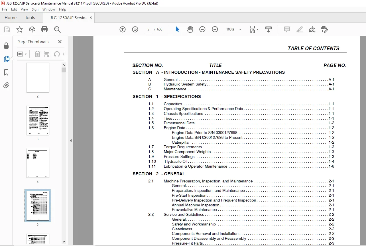
TABLE OF CONTENTS:
JLG 1250AJP Service & Maintenance Manual 3121171 – PDF DOWNLOAD
Section A INTRODUCTION – MAINTENANCE SAFETY PRECAUTIONS 3
A General 3
B Hydraulic System Safety 3
C Maintenance 3
Section 1 Specifications 19
1 1 Capacities 19
1 2 Operating Specifications & Performance Data 19
1 3 Chassis Specifications 19
1 4 Tires 19
1 5 Dimensional Data 20
1 6 Engine Data 20
Engine Data Prior to S/N 0300127698 20
Engine Data S/N 0300127698 to Present 20
Caterpillar 20
1 7 Torque Requirements 21
1 8 Major Component Weights 21
1 9 Pressure Settings 21
1 10 Hydraulic Oil 22
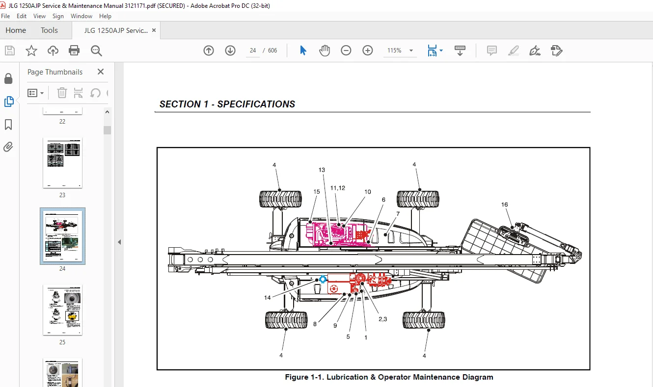
1 11 Lubrication & Operator Maintenance 24
Section 2 General 39
2 1 Machine Preparation, Inspection, and Maintenance 39
General 39
Preparation, Inspection, and Maintenance 39
Pre-Start Inspection 39
Pre-Delivery Inspection and Frequent Inspection 39
Annual Machine Inspection 39
Preventative Maintenance 39
2 2 Service and Guidelines 40
General 40
Safety and Workmanship 40
Cleanliness 40
Components Removal and Installation 40
Component Disassembly and Reassembly 41
Pressure-Fit Parts 41
Bearings 41
Gaskets 41
Bolt Usage and Torque Application 41
Hydraulic Lines and Electrical Wiring 41
Hydraulic System 41
Lubrication 41
Battery 41
Lubrication and Servicing 41
2 3 Lubrication and Information 41
Hydraulic System 41
Hydraulic Oil 42
Changing Hydraulic Oil 42
Lubrication Specifications 42
2 4 Cylinder Drift Test 42
Platform Drift 42
Cylinder Drift 43
2 5 Pins and Composite Bearing Repair Guidelines 43
2 6 Welding on JLG Equipment 43
Do the Following When Welding on JLG Equipment 43
Do NOT Do the Following When Welding on JLG Equipment 43
Section 3 1Chassis & Turntable 49
3 1 Tires & Wheels 49
Tire Inflation 49
Tire Damage 49
Tire Replacement 49
Wheel and Tire Replacement 49
Wheel Installation 50
3 2 Axle Extension System 51
3 3 Axle Limit Switch Adjustment Procedure 51
3 4 Drive System 52
3 5 Steering Control System 52
3 6 Drive/Steering Speed Control 53
3 7 Traction Control System 53
3 8 Drive Orientation System 53
3 9 Ground Control Enable System 53
3 10 Oscillating Axle System 62
3 11 Oscillating Axle Bleeding Procedure and Lockout Test 62
Lockout Cylinder Bleeding 62
Oscillating Axle Lockout Test 63
3 12 Drive Hub (Prior to S/N 100128) 64
Disassembly 64
Disassembly of Cover 64
Disassembly of the First Stage Planetary Assembly (7) 64
Disassembly of Second Stage Planet Gears (1) 64
Assembly of First Stage Planetary Assembly (7) 65
Assembly of End Cover Unit (8) 65
Final Assembly 65
Initial Start-up And After Repairs 65
Oil Change Interval-Gear Drive 65
3 13 Drive Hub – Bonfiglioli (S/N 100128 to Present) 68
Product Identification 68
Hydraulic Motor Installation 68
Installation of the Wheel Drive on the Machine 68
Start Up and Running In 68
General Information 69
Connecting the Brake 69
Filling-up the Gearbox with Lubricating Oil 69
Gearbox Disengagement 71
Maintenance Information 73
Periodic Maintenance 73
Changing the Lubricating oil 73
Troubleshooting 74
Disassembly Information 74
Disassembly 74
Inspection of Parts 82
Assembly 83
Final Test and Reinstallation 93
3 14 Drive Hub – Reggiana Riduttori (S/N 134389 to Present) 98
Symbol Nomenclature 98
Tools 98
Disassembly 103
Assembly 107
3 15 Swing Drive 113
Roll and Leak Testing 113
Tightening and Torquing Bolts 113
Motor Control Valve Disassembly 114
Motor and Brake Disassembly 115
Main Disassembly 116
Hub-Shaft Disassembly 117
Carrier Disassembly 118
Hub-Shaft Sub-Assembly 119
Carrier Sub-Assembly 120
Main Assembly 122
Motor and Brake Assembly 124
Motor Control Valve Assembly 125
3 16 Swing Brake 126
Pre-Installation Checks 126
Installation 127
Maintenance 127
Disassembly 127
Examination 127
Assembly 127
3 17 Swing Motor 129
Disassembly and inspection 129
Assembly 136
One Piece Stator Construction 143
3 18 Procedure For Setting Gear Backlash 144
3 19 Swing Drive Lubrication 145
3 20 Swing Bearing 146
Turntable Bearing Mounting Bolt Condition Check 146
Wear Tolerance 149
Swing Bearing Removal 149
Swing Bearing Installation 151
Swing Bearing Torque Values 151
3 21 Swing Speed Proportioning 152
3 22 Chassis Tilt Indicator System 153
3 23 Rotary Coupling 154
3 24 Generator 157
Every 250 hours 157
Every 500 hours 157
Overload Protection 158
Inspecting Brushes, Replacing Brushes, and Cleaning Slip Rings 158
inspecting brush position 158
inspecting brushes 158
CLEANING SLIP RINGS 158
3 25 Cold Weather Package 160
3 26 Engine 160
Glow Plugs 160
Checking Oil Level 160
Changing Engine Oil 160
Changing the Oil Filter 162
Replacing the Fuel Filter 163
Cleaning the Fuel Strainer 163
Removal 164
Installation 167
3 27 Deutz EMR 2 (S/N 87575 to Present) 168
3 28 Bio Fuel in Deutz Engines 181
General 181
Bio Fuel 181
Permitted bio-diesel fuels 181
approved engines 181
Basic conditions to be observed 181
Plant oil 182
Biological Contamination In Fuels 182
Symptoms 182
Cause 182
Preventive measures 182
Fuel additives 182
3 29 CAT DGC DIAGNOSTIC SUPPORT AND TROUBLE CODE DEFINITIONS 183
List of Abbreviations in this Section 185
Diagnostic Trouble Codes 187
CAN 187
MIL Output 187
DTC 116- ECT Higher Than Expected Stage 1 188
DTC 117- ECT/CHT Low Voltage 189
DTC 118- ECT/CHT High Voltage 191
DTC 122- TPS1 Signal Voltage Low 193
DTC 123- TPS1 Signal Voltage High 195
DTC 217- ECT Higher Than Expected 2 197
DTC 219- RPM Higher Than Max Allowed Governed Speed 198
DTC 336- Crank Signal Input Noise 199
DTC 337- Loss of Crank Input Signal 201
DTC 521- Oil Pressure Sender/Switch High Pressure 202
DTC 524- Oil Pressure Low 203
DTC 562- Battery Voltage (VBat) Low 205
DTC 563- Battery Voltage (VBat) High 207
DTC 601- Microprocessor Failure – FLASH 209
DTC 604- Microprocessor Failure – RAM 211
DTC 606- Microprocessor Failure – COP 213
DTC 642- 5 Volt External Low Voltage 215
DTC 643- 5 Volt External High Voltage 216
DTC 1612- Microprocessor Failure – RTI 1 217
DTC 1613- Microprocessor Failure – RTI 2 218
DTC 1614- Microprocessor Failure – RTI 3 220
DTC 1615- Microprocessor Failure – A/D 222
DTC 1616- Microprocessor Failure – interrupt 224
DTC 1625- CAN J1939 Shutdown Request 226
DTC 1626- CAN J1939 Transmit (Tx) Fault 227
DTC 1627- CAN J1939 Receive (Rx) Fault 228
DTC 1628- CAN Address Conflict Failure 229
DTC 1629- J1939 TSC1 Message Reciept Loss 231
DTC 1652- TPS1 Loss of Communications 232
DTC 2111- Unable to Reach Lower TPS 233
DTC 2112- Unable to Reach Higher TPS 235
DTC 9999- Throttle Actuator Failsafe Spring Failure 236
DTC to SPN/FMI Table 237
3 30 Auxiliary Power System 238
3 31 Counterweight 238
Section 4 Boom & Platform 241
4 1 Platform Control Enable System 241
4 2 Transport Position Sensing System 241
4 3 Beyond Transport – Drive Speed Cutback System 241
4 4 Drive/Steer – Boom Function Interlock System (CE ONLY) 241
4 5 Jib Stow System 242
4 6 Envelope Control System 242
4 7 Tower Path Control System 243
4 8 Automatic Main Boom Control System 243
4 9 Electrical Retrieval System 248
4 10 Hydraulic Retrieval System 248
4 11 Controlled Boom Angle System 248
4 12 Slow Down System 248
4 13 Dual Capacity System 249
4 14 Hydraulic System Warm Up 249
4 15 Reduced Platform Heights 249
4 16 Electronic Platform Leveling 250
4 17 Main Boom 250
Disassembly 250
Assembly 252
4 18 Tower Boom 259
Installation and Assembly 259
Pin Clamp Installation Procedure 275
4 19 Main Boom Transport Angle Switch 294
Analyzer Readings 294
Possible Faults 295
4 20 Tower Transport Length Switch 295
Analyzer Readings 295
Possible Faults 296
4 21 Main Boom Transport Length Switches 297
Analyzer Readings 297
Possible Faults 298
4 22 Dual Capacity Switches 298
Analyzer Readings 298
Possible Faults 299
4 23 Tower Telescope Cylinder 302
Removal 302
Installation 306
4 24 Tower Lift Cylinder 308
Removal 308
Installation 312
4 25 Main Lift Cylinder 316
Removal 316
Installation 319
4 26 Main Boom Telescope Cylinder 320
Removal 320
Installation 324
4 27 Powertrack Maintenance 326
One Piece Bracket Maintenance 326
Two Piece Bracket Maintenance 328
Snap Rings and Screws 329
4 28 Hose Routing Procedure 334
4 29 Electronic Platform Leveling 335
Description 335
Normal Operation 335
4 30 Tower Boom Drift Test 337
4 31 Rotary Actuator 339
Theory of Operation 339
Required Tools 339
Disassembly 342
Inspection 346
Assembly 346
Greasing Thrust Washers 351
Installing Counterbalance Valve 351
Testing the Actuator 351
Bleeding After Installation 353
Section 5 Hydraulics 355
5 1 Lubricating O-Rings in the Hydraulic System 355
Cup and Brush 355
Dip Method 356
Spray Method 356
Brush-on Method 356
5 2 Cylinder Repair 357
Disassembly 357
Cleaning and Inspection 372
Assembly 374
5 3 Counterbalance Valve Check 378
5 4 Hydraulic Tank 379
5 5 Hydraulic Return Filter 380
5 6 Enable Valves 399
Removal 399
Installation 399
Air Purge Procedure for Non-Calibrated Machines 400
Air Purge Procedure for Calibrated Machines 400
5 7 Pressure Setting Procedure 401
Set Up of the Function Pump 401
Adjustments made at the Main Valve Bank 402
Adjustments Made at the Frame Valve Bank 406
Adjustments Made at the Platform Valve Bank 410
5 8 Drive Pumps 411
Troubleshooting Procedure 411
Charge Pressure Relief Valve Adjustment 414
Mechanical Centering of Pump 415
Hydraulic Centering of Control Modules 415
High Pressure Relief Valve Adjustments 416
Removal and inspection of charge pump 416
Routine Maintenance 417
Removal and Installation of Shaft Seal 419
5 9 Function Pump 421
Spare Parts 421
Sealing the Drive Shaft 422
Disassembly and Assembly of the Complete Unit 423
Assembly 426
Adjustments 427
Tightening Torques 427
Pump Control Disassembly For Cleaning 429
5 10 Drive & Function Pump Start Up Procedures 431
Start-Up Procedure 431
Section 6 JLG Control System 433
6 1 Introduction 433
6 2 CANbus Communications 434
6 3 Calibration Instructions 437
6 4 To Connect the JLG Control System Analyzer 450
6 5 Using the Analyzer 450
6 6 Changing the Access Level of the Hand Held Analyzer 451
6 7 Adjusting Parameters Using the Hand Held Analyzer 452
6 8 Machine Setup 452
6 9 Machine Orientation When Setting Speeds 462
Test Notes 462
6 10 System Test 463
Test from the Platform 463
Test from the Ground Station 466
6 11 Calibrating Steer 471
6 12 Calibrating Drive 474
6 13 Calibrating Boom Valves 477
6 14 Electronic Platform Leveling 480
Platform Leveling Fault Warning 480
Fault Response 480
CAN Errors 481
Additional Platform and Jib Valves 481
6 15 Calibrating Platform Level 482
STEP 1: SETTING THE PLATFORM VALVE MINIMUMS 482
STEP 2: BLEEDING THE PLATFORM VALVES 482
STEP 4: CALIBRATING THE PLATFORM LEVEL UP AND DOWN VALVE CRACKPOINTS 483
6 16 Calibrating Tilt Sensor 484
6 17 Boom Sensor Calibration 486
General Notes: 486
Step 1 – Position 1 487
Step 2 – Position 2 488
Step 3 – Position 3 489
Step 4 – Position 4 490
Step 5 – Position 5 491
Step 6 – Position 6 492
Step 7 – Position 7 493
Step 8 – Position 8 494
Step 9 – Position 9 495
Step 10 – Position 10 496
Step 11 – Position 11 497
6 18 Boom Control System (BCS) Violation 498
“UNLOCK BOOM” Calibration Procedure 498
6 19 CANbus Troubleshooting 538
CANbus Communication Failure 544
Load Moment Pin Troubleshooting 557
Section 7 Basic Electrical Information & Schematics 561
7 1 General 561
7 2 Multimeter Basics 561
Grounding 561
Backprobing 561
Min/Max 561
Polarity 561
Scale 561
Voltage Measurement 561
Resistance Measurement 562
Continuity Measurement 562
Current Measurement 563
7 3 Applying Silicone Dielectric Compound to Electrical Connections 563
7 4 AMP Connector 564
Applying Silicone Dielectric Compound to AMP Connectors 564
Assembly 564
Disassembly 566
Wedge Lock 566
Service – Voltage Reading 566
7 5 Deutsch Connectors 568
DT/DTP Series Assembly 568
DT/DTP Series Disassembly 568
HD30/HDP20 Series Assembly 569
HD30/HDP20 Series Disassembly 569Section A INTRODUCTION – MAINTENANCE SAFETY PRECAUTIONS 3
A General 3
B Hydraulic System Safety 3
C Maintenance 3
Section 1 Specifications 19
1 1 Capacities 19
1 2 Operating Specifications & Performance Data 19
1 3 Chassis Specifications 19
1 4 Tires 19
1 5 Dimensional Data 20
1 6 Engine Data 20
Engine Data Prior to S/N 0300127698 20
Engine Data S/N 0300127698 to Present 20
Caterpillar 20
1 7 Torque Requirements 21
1 8 Major Component Weights 21
1 9 Pressure Settings 21
1 10 Hydraulic Oil 22
1 11 Lubrication & Operator Maintenance 24
Section 2 General 39
2 1 Machine Preparation, Inspection, and Maintenance 39
General 39
Preparation, Inspection, and Maintenance 39
Pre-Start Inspection 39
Pre-Delivery Inspection and Frequent Inspection 39
Annual Machine Inspection 39
Preventative Maintenance 39
2 2 Service and Guidelines 40
General 40
Safety and Workmanship 40
Cleanliness 40
Components Removal and Installation 40
Component Disassembly and Reassembly 41
Pressure-Fit Parts 41
Bearings 41
Gaskets 41
Bolt Usage and Torque Application 41
Hydraulic Lines and Electrical Wiring 41
Hydraulic System 41
Lubrication 41
Battery 41
Lubrication and Servicing 41
2 3 Lubrication and Information 41
Hydraulic System 41
Hydraulic Oil 42
Changing Hydraulic Oil 42
Lubrication Specifications 42
2 4 Cylinder Drift Test 42
Platform Drift 42
Cylinder Drift 43
2 5 Pins and Composite Bearing Repair Guidelines 43
2 6 Welding on JLG Equipment 43
Do the Following When Welding on JLG Equipment 43
Do NOT Do the Following When Welding on JLG Equipment 43
Section 3 1Chassis & Turntable 49
3 1 Tires & Wheels 49
Tire Inflation 49
Tire Damage 49
Tire Replacement 49
Wheel and Tire Replacement 49
Wheel Installation 50
3 2 Axle Extension System 51
3 3 Axle Limit Switch Adjustment Procedure 51
3 4 Drive System 52
3 5 Steering Control System 52
3 6 Drive/Steering Speed Control 53
3 7 Traction Control System 53
3 8 Drive Orientation System 53
3 9 Ground Control Enable System 53
3 10 Oscillating Axle System 62
3 11 Oscillating Axle Bleeding Procedure and Lockout Test 62
Lockout Cylinder Bleeding 62
Oscillating Axle Lockout Test 63
3 12 Drive Hub (Prior to S/N 100128) 64
Disassembly 64
Disassembly of Cover 64
Disassembly of the First Stage Planetary Assembly (7) 64
Disassembly of Second Stage Planet Gears (1) 64
Assembly of First Stage Planetary Assembly (7) 65
Assembly of End Cover Unit (8) 65
Final Assembly 65
Initial Start-up And After Repairs 65
Oil Change Interval-Gear Drive 65
3 13 Drive Hub – Bonfiglioli (S/N 100128 to Present) 68
Product Identification 68
Hydraulic Motor Installation 68
Installation of the Wheel Drive on the Machine 68
Start Up and Running In 68
General Information 69
Connecting the Brake 69
Filling-up the Gearbox with Lubricating Oil 69
Gearbox Disengagement 71
Maintenance Information 73
Periodic Maintenance 73
Changing the Lubricating oil 73
Troubleshooting 74
Disassembly Information 74
Disassembly 74
Inspection of Parts 82
Assembly 83
Final Test and Reinstallation 93
3 14 Drive Hub – Reggiana Riduttori (S/N 134389 to Present) 98
Symbol Nomenclature 98
Tools 98
Disassembly 103
Assembly 107
3 15 Swing Drive 113
Roll and Leak Testing 113
Tightening and Torquing Bolts 113
Motor Control Valve Disassembly 114
Motor and Brake Disassembly 115
Main Disassembly 116
Hub-Shaft Disassembly 117
Carrier Disassembly 118
Hub-Shaft Sub-Assembly 119
Carrier Sub-Assembly 120
Main Assembly 122
Motor and Brake Assembly 124
Motor Control Valve Assembly 125
3 16 Swing Brake 126
Pre-Installation Checks 126
Installation 127
Maintenance 127
Disassembly 127
Examination 127
Assembly 127
3 17 Swing Motor 129
Disassembly and inspection 129
Assembly 136
One Piece Stator Construction 143
3 18 Procedure For Setting Gear Backlash 144
3 19 Swing Drive Lubrication 145
3 20 Swing Bearing 146
Turntable Bearing Mounting Bolt Condition Check 146
Wear Tolerance 149
Swing Bearing Removal 149
Swing Bearing Installation 151
Swing Bearing Torque Values 151
3 21 Swing Speed Proportioning 152
3 22 Chassis Tilt Indicator System 153
3 23 Rotary Coupling 154
3 24 Generator 157
Every 250 hours 157
Every 500 hours 157
Overload Protection 158
Inspecting Brushes, Replacing Brushes, and Cleaning Slip Rings 158
inspecting brush position 158
inspecting brushes 158
CLEANING SLIP RINGS 158
3 25 Cold Weather Package 160
3 26 Engine 160
Glow Plugs 160
Checking Oil Level 160
Changing Engine Oil 160
Changing the Oil Filter 162
Replacing the Fuel Filter 163
Cleaning the Fuel Strainer 163
Removal 164
Installation 167
3 27 Deutz EMR 2 (S/N 87575 to Present) 168
3 28 Bio Fuel in Deutz Engines 181
General 181
Bio Fuel 181
Permitted bio-diesel fuels 181
approved engines 181
Basic conditions to be observed 181
Plant oil 182
Biological Contamination In Fuels 182
Symptoms 182
Cause 182
Preventive measures 182
Fuel additives 182
3 29 CAT DGC DIAGNOSTIC SUPPORT AND TROUBLE CODE DEFINITIONS 183
List of Abbreviations in this Section 185
Diagnostic Trouble Codes 187
CAN 187
MIL Output 187
DTC 116- ECT Higher Than Expected Stage 1 188
DTC 117- ECT/CHT Low Voltage 189
DTC 118- ECT/CHT High Voltage 191
DTC 122- TPS1 Signal Voltage Low 193
DTC 123- TPS1 Signal Voltage High 195
DTC 217- ECT Higher Than Expected 2 197
DTC 219- RPM Higher Than Max Allowed Governed Speed 198
DTC 336- Crank Signal Input Noise 199
DTC 337- Loss of Crank Input Signal 201
DTC 521- Oil Pressure Sender/Switch High Pressure 202
DTC 524- Oil Pressure Low 203
DTC 562- Battery Voltage (VBat) Low 205
DTC 563- Battery Voltage (VBat) High 207
DTC 601- Microprocessor Failure – FLASH 209
DTC 604- Microprocessor Failure – RAM 211
DTC 606- Microprocessor Failure – COP 213
DTC 642- 5 Volt External Low Voltage 215
DTC 643- 5 Volt External High Voltage 216
DTC 1612- Microprocessor Failure – RTI 1 217
DTC 1613- Microprocessor Failure – RTI 2 218
DTC 1614- Microprocessor Failure – RTI 3 220
DTC 1615- Microprocessor Failure – A/D 222
DTC 1616- Microprocessor Failure – interrupt 224
DTC 1625- CAN J1939 Shutdown Request 226
DTC 1626- CAN J1939 Transmit (Tx) Fault 227
DTC 1627- CAN J1939 Receive (Rx) Fault 228
DTC 1628- CAN Address Conflict Failure 229
DTC 1629- J1939 TSC1 Message Reciept Loss 231
DTC 1652- TPS1 Loss of Communications 232
DTC 2111- Unable to Reach Lower TPS 233
DTC 2112- Unable to Reach Higher TPS 235
DTC 9999- Throttle Actuator Failsafe Spring Failure 236
DTC to SPN/FMI Table 237
3 30 Auxiliary Power System 238
3 31 Counterweight 238
Section 4 Boom & Platform 241
4 1 Platform Control Enable System 241
4 2 Transport Position Sensing System 241
4 3 Beyond Transport – Drive Speed Cutback System 241
4 4 Drive/Steer – Boom Function Interlock System (CE ONLY) 241
4 5 Jib Stow System 242
4 6 Envelope Control System 242
4 7 Tower Path Control System 243
4 8 Automatic Main Boom Control System 243
4 9 Electrical Retrieval System 248
4 10 Hydraulic Retrieval System 248
4 11 Controlled Boom Angle System 248
4 12 Slow Down System 248
4 13 Dual Capacity System 249
4 14 Hydraulic System Warm Up 249
4 15 Reduced Platform Heights 249
4 16 Electronic Platform Leveling 250
4 17 Main Boom 250
Disassembly 250
Assembly 252
4 18 Tower Boom 259
Installation and Assembly 259
Pin Clamp Installation Procedure 275
4 19 Main Boom Transport Angle Switch 294
Analyzer Readings 294
Possible Faults 295
4 20 Tower Transport Length Switch 295
Analyzer Readings 295
Possible Faults 296
4 21 Main Boom Transport Length Switches 297
Analyzer Readings 297
Possible Faults 298
4 22 Dual Capacity Switches 298
Analyzer Readings 298
Possible Faults 299
4 23 Tower Telescope Cylinder 302
Removal 302
Installation 306
4 24 Tower Lift Cylinder 308
Removal 308
Installation 312
4 25 Main Lift Cylinder 316
Removal 316
Installation 319
4 26 Main Boom Telescope Cylinder 320
Removal 320
Installation 324
4 27 Powertrack Maintenance 326
One Piece Bracket Maintenance 326
Two Piece Bracket Maintenance 328
Snap Rings and Screws 329
4 28 Hose Routing Procedure 334
4 29 Electronic Platform Leveling 335
Description 335
Normal Operation 335
4 30 Tower Boom Drift Test 337
4 31 Rotary Actuator 339
Theory of Operation 339
Required Tools 339
Disassembly 342
Inspection 346
Assembly 346
Greasing Thrust Washers 351
Installing Counterbalance Valve 351
Testing the Actuator 351
Bleeding After Installation 353
Section 5 Hydraulics 355
5 1 Lubricating O-Rings in the Hydraulic System 355
Cup and Brush 355
Dip Method 356
Spray Method 356
Brush-on Method 356
5 2 Cylinder Repair 357
Disassembly 357
Cleaning and Inspection 372
Assembly 374
5 3 Counterbalance Valve Check 378
5 4 Hydraulic Tank 379
5 5 Hydraulic Return Filter 380
5 6 Enable Valves 399
Removal 399
Installation 399
Air Purge Procedure for Non-Calibrated Machines 400
Air Purge Procedure for Calibrated Machines 400
5 7 Pressure Setting Procedure 401
Set Up of the Function Pump 401
Adjustments made at the Main Valve Bank 402
Adjustments Made at the Frame Valve Bank 406
Adjustments Made at the Platform Valve Bank 410
5 8 Drive Pumps 411
Troubleshooting Procedure 411
Charge Pressure Relief Valve Adjustment 414
Mechanical Centering of Pump 415
Hydraulic Centering of Control Modules 415
High Pressure Relief Valve Adjustments 416
Removal and inspection of charge pump 416
Routine Maintenance 417
Removal and Installation of Shaft Seal 419
5 9 Function Pump 421
Spare Parts 421
Sealing the Drive Shaft 422
Disassembly and Assembly of the Complete Unit 423
Assembly 426
Adjustments 427
Tightening Torques 427
Pump Control Disassembly For Cleaning 429
5 10 Drive & Function Pump Start Up Procedures 431
Start-Up Procedure 431
Section 6 JLG Control System 433
6 1 Introduction 433
6 2 CANbus Communications 434
6 3 Calibration Instructions 437
6 4 To Connect the JLG Control System Analyzer 450
6 5 Using the Analyzer 450
6 6 Changing the Access Level of the Hand Held Analyzer 451
6 7 Adjusting Parameters Using the Hand Held Analyzer 452
6 8 Machine Setup 452
6 9 Machine Orientation When Setting Speeds 462
Test Notes 462
6 10 System Test 463
Test from the Platform 463
Test from the Ground Station 466
6 11 Calibrating Steer 471
6 12 Calibrating Drive 474
6 13 Calibrating Boom Valves 477
6 14 Electronic Platform Leveling 480
Platform Leveling Fault Warning 480
Fault Response 480
CAN Errors 481
Additional Platform and Jib Valves 481
6 15 Calibrating Platform Level 482
STEP 1: SETTING THE PLATFORM VALVE MINIMUMS 482
STEP 2: BLEEDING THE PLATFORM VALVES 482
STEP 4: CALIBRATING THE PLATFORM LEVEL UP AND DOWN VALVE CRACKPOINTS 483
6 16 Calibrating Tilt Sensor 484
6 17 Boom Sensor Calibration 486
General Notes: 486
Step 1 – Position 1 487
Step 2 – Position 2 488
Step 3 – Position 3 489
Step 4 – Position 4 490
Step 5 – Position 5 491
Step 6 – Position 6 492
Step 7 – Position 7 493
Step 8 – Position 8 494
Step 9 – Position 9 495
Step 10 – Position 10 496
Step 11 – Position 11 497
6 18 Boom Control System (BCS) Violation 498
“UNLOCK BOOM” Calibration Procedure 498
6 19 CANbus Troubleshooting 538
CANbus Communication Failure 544
Load Moment Pin Troubleshooting 557
Section 7 Basic Electrical Information & Schematics 561
7 1 General 561
7 2 Multimeter Basics 561
Grounding 561
Backprobing 561
Min/Max 561
Polarity 561
Scale 561
Voltage Measurement 561
Resistance Measurement 562
Continuity Measurement 562
Current Measurement 563
7 3 Applying Silicone Dielectric Compound to Electrical Connections 563
7 4 AMP Connector 564
Applying Silicone Dielectric Compound to AMP Connectors 564
Assembly 564
Disassembly 566
Wedge Lock 566
Service – Voltage Reading 566
7 5 Deutsch Connectors 568
DT/DTP Series Assembly 568
DT/DTP Series Disassembly 568
HD30/HDP20 Series Assembly 569
HD30/HDP20 Series Disassembly 569
Need help? Contact: [email protected]
PLEASE NOTE:
- This is the SAME exact manual used by your dealers to fix your vehicle.
- The same can be yours in the next 2-3 mins as you will be directed to the download page immediately after paying for the manual.
- Any queries / doubts regarding your purchase, please feel free to contact [email protected]
S.M