JLG 3508PS 3509PS 3512PS 3513PS 4008PS 4009PS 4012PS 4013PS 4017PS Telehandler Parts Manual – PDF DOWNLOAD
Original price was: $90.00.$21.95Current price is: $21.95.
JLG 3508PS 3509PS 3512PS 3513PS 4008PS 4009PS 4012PS 4013PS 4017PS Telehandler Parts Manual – PDF DOWNLOAD
3121853
Description
JLG 3508PS 3509PS 3512PS 3513PS 4008PS 4009PS 4012PS 4013PS 4017PS Telehandler Parts Manual – PDF DOWNLOAD
FILE DETAILS:
JLG 3508PS 3509PS 3512PS 3513PS 4008PS 4009PS 4012PS 4013PS 4017PS Telehandler Parts Manual – PDF DOWNLOAD
Format: PDF
Language: English
Brand: JLG GRADALL
TABLE OF CONTENTS:
JLG 3508PS 3509PS 3512PS 3513PS 4008PS 4009PS 4012PS 4013PS 4017PS Telehandler Parts Manual – PDF DOWNLOAD
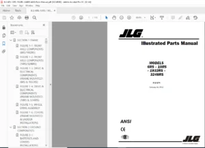
SECTION 1 –
FRAME & ATTACHING PARTS 1-1
1-1 Basic Components Installation 1-2
1-2 Engine Hood Installation 1-4
1-3 Engine Cover Installation 1-6
1-4 Toolbox Installation 1-10
1-5 Counterweight Assembly 1-12
1-6 Headlight & Mirror Bracket 1-14
1-7 Rear Boom Cover Installation 1-16
1-8 Axle Installation 1-18
1-9 Fenders Installation 1-26
1-10 Stabilizer Installation 1-28
1-11 Stabilizer Installation for Platform 1-30
1-12 Stabilizer Installation Equipped W/LMIS 1-32
SECTION 2 –
BOOM 2-1
2-1 Boom Assembly 2-2
2-2 First Boom Section Assembly 2-6
2-3 Second Boom Section Assembly 2-10
2-4 Third Boom Section Assembly 2-14
2-5 Quick Switch Assembly 2-16
SECTION 3 –
ATTACHMENTS 3-1
3-1 Manure Bucket 3-2
3-2 4 in 1 Bucket 3-4
3-3 Fork Mounted Hook 3-6
3-4 Buckets 3-8
3-5 Carriage Assembly w/Loadguard 3-10
3-6 Side Shift Carriage Assembly 3-12
3-7 Fork Positioning Carriage Assembly 3-14
3-8 Fork Tines 3-16
3-9 Fork Tine Extension 3-18
3-10 Truss Boom 3-20
3-11 Platform Assembly, Adapter & Pedestal 3-22
3-12 Platform Assembly, Base & Railings 3-24
3-13 Platform Assembly, Electrical 3-26
3-14 Platform Assembly, Miscellaneous 3-30
3-15 Concrete Ladle 3-32
3-16 Crane Hook 3-34
3-17 Extending Jib (Australia) 3-36
3-18 Adjustable Boom Truss (Australia
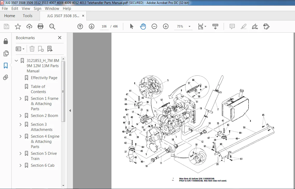
4-1 Engine Installation 4-2
4-2 Engine Assembly 4-8
4-3 Tank & Fuel Supply Installation 4-14
4-4 Cooling System Installation 4-18
4-5 Air Cleaner Installation 4-20
4-6 Muffler Installation 4-26
4-7 Air Collector, Condenser & Radiator 4-30
4-8 Transmission Assembly 4-34
4-9 Transmission Assembly – Converter Housing 4-36
4-10 Transmission Assembly – Case & Plate 4-38
4-11 Transmission Assembly – Torque Converter 4-40
4-12 Transmission Assembly – Gear Group 4-42
4-13 Transmission Assembly – Pump Drive Group 4-46
4-14 Transmission Assembly – Charge Pump 4-48
4-15 Transmission Assembly – Reverse Idler 4-50
4-16 Transmission Assembly – Forward & Reverse Shaft 4-52
4-17 Transmission Assembly – High 4th & 3rd Shaft 4-54
4-18 Transmission Assembly – 1st & 2nd Shaft 4-58
4-19 Transmission Assembly – Output Shaft 4-60
4-20 Transmission Assembly – Control & Modulation Valve Assembly 4-62
4-21 Transmission Assembly – Drive Plate 4-70
4-22 Transmission Assembly – Drop Box 4-72
SECTION 5 –
DRIVE TRAIN 5-1
5-1 Front Axle Assembly 5-2
5-2 Front Axle Assembly – Differential Housing Components 5-4
5-3 Front Axle Assembly – Internal Differential Housing Components 5-6
5-4 Front Axle Assembly – External Axle Components 5-8
5-5 Front Axle Assembly – Brake Components 5-12
5-6 Front Axle Assembly – Steering Components 5-14
5-7 Front Axle Assembly – Oscillation Support Components 5-16
5-8 Rear Axle Assembly 5-18
5-9 Rear Axle Assembly – Differential Housing Components 5-20
5-10 Rear Axle Assembly – Internal Differential Components 5-22
5-11 Rear Axle Assembly – External Axle Components 5-24
5-12 Rear Axle Assembly – Brake Components 5-28
5-13 Rear Axle Assembly – Steering Components 5-30
5-14 Rear Axle Assembly – Oscillation Support Components 5-32
5-15 Tire & Wheel Assembly 5-34
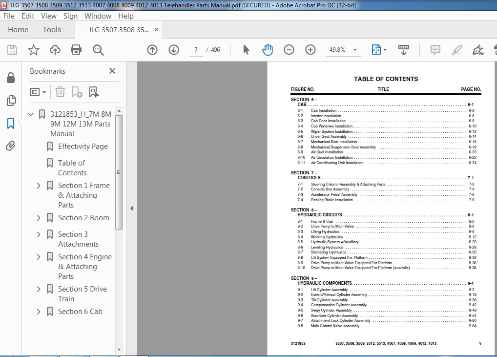
6-1 Cab Installation 6-2
6-2 Interior Installation 6-6
6-3 Cab Door Installation 6-8
6-4 Cab Windows Installation 6-10
6-5 Wiper System Installation 6-12
6-6 Driver Seat Assembly 6-14
6-7 Mechanical Seat Installation 6-16
6-8 Mechanical Suspension Seat Assembly 6-18
6-9 Air Duct Installation 6-20
6-10 Air Circulation Installation 6-22
6-11 Air Conditioning Unit Installation 6-24
SECTION 7 –
CONTROLS 7-1
7-1 Steering Column Assembly & Attaching Parts 7-2
7-2 Console Box Assembly 7-4
7-3 Accelerator Pedal Assembly 7-6
7-4 Parking Brake Installation 7-8
SECTION 8 –
HYDRAULIC CIRCUITS 8-1
8-1 Frame & Cab 8-2
8-2 Drive Pump to Main Valve 8-6
8-3 Lifting Hydraulics 8-8
8-4 Working Hydraulics 8-12
8-5 Hydraulic System w/Auxiliary 8-20
8-6 Leveling Hydraulics 8-28
8-7 Stabilizing Hydraulics 8-30
8-8 Lift System Equipped For Platform 8-32
8-9 Drive Pump to Main Valve Equipped For Platform 8-36
8-10 Drive Pump to Main Valve Equipped For Platform (Australia) 8-38
SECTION 9 –
HYDRAULIC COMPONENTS 9-1
9-1 Lift Cylinder Assembly 9-2
9-2 Extend/Retract Cylinder Assembly 9-18
9-3 Tilt Cylinder Assembly 9-38
9-4 Compensation Cylinder Assembly 9-42
9-5 Sway Cylinder Assembly 9-48
9-6 Stabilizer Cylinder Assembly 9-54
9-7 Attachment Lock Cylinder Assembly 9-60
9-8 Main Control Valve Assembly .
FIGURE NOTITLE PAGE NO.
3507, 3508, 3509, 3512, vi 3513, 4007, 4008, 4009, 4012, 4013 3121853
9-9 Engine Drive Pump Assembly 9-68
9-10 Hydraulic Tank Assembly 9-72
9-11 Return Filter Assembly 9-74
9-12 ERS Control Valve Assembly 9-76
9-13 Auxiliary Power Pump 9-78
SECTION 10 –
ELECTRICAL 10-1
10-1 Instrument Panel Assembly 10-2
10-2 Accessories Panel Assembly 10-6
10-3 Gear & Valve 10-8
10-4 Rear of Machine 10-10
10-5 Engine 10-12
10-6 Display Panel 10-16
10-7 Tail Light & Bracket Installation 10-18
10-8 Sensor Assembly 10-22
10-9 Tier II Fuel Solenoid Wire 10-28
10-10 Tier II Engine Harness Wire 10-30
10-11 Cab Electrical Installation with Platform 10-32
10-12 Electrical Installation on Boom with Platform 10-36
10-13 ERS System Installation 10-40
10-14 Rear Harness 10-44
10-15 Sensor Assembly with Platform 10-46
10-16 LMIS Installation 10-48
10-17 LMIS Audible Tower/Beacon Installation 10-50
10-18 LMIS Harness 10-52
10-19 Stabilizer Harness Equipped W/LMIS 10-54
SECTION 11 –
DECALS 11-1
11-1 Decals – Main 11-2
11-2 Decals – Cab 11-6
SECTION 12 –
OPTIONS 12-1
12-1 Hydraulic Hitch Kit 12-2
12-2 Field Hitch Assembly 12-4
12-3 Trailer Coupling Assembly 12-6
12-4 Front Cab Glass Shield 12-8
12-5 Air Suspension Seat Installation 12-10
12-6 Air Suspension Seat 12-12
12-7 Draw Bar Coupling 12-14
12-8 License Plate Light & Towing Plate Installation 12-16
12-9 Rear Access Door Kit .
12-10 Knurl Function Kit 12-20
12-11 Agricultural Kit 12-22
12-12 Hydraulic Agricultural Kit 12-24
12-13 Battery Switch 12-26
12-14 Boom Stop Installation 12-28
12-15 Ground Wire Installation 12-30
12-16 7-Pin Trailer Socket Installation 12-32
12-17 Hose Assembly Retrofit Kit 12-34
SECTION 13 –
RECOMMENDED SPARE PARTS 13-1
SECTION 14 – PART NUMBER INDEX
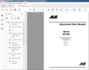
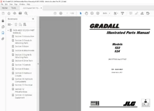
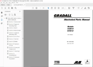
JLG 3508PS 3509PS 3512PS 3513PS 4008PS 4009PS 4012PS 4013PS 4017PS TELEHANDLER PARTS MANUAL – PDF DOWNLOAD:
IMAGES PREVIEW OF THE MANUAL:
PLEASE NOTE:
- This is the same manual used by the dealers to diagnose and troubleshoot your vehicle
- You will be directed to the download page as soon as the purchase is completed. The whole payment and downloading process will take anywhere between 2-5 minutes
- Need any other service / repair / parts manual, please feel free to contact [email protected] . We still have 50,000 manuals unlisted