JLG 450A 450AJ Service & Maintenance Manual 3120869 – PDF DOWNLOAD
$25.95
JLG 450A 450AJ Service & Maintenance Manual 3120869 – PDF DOWNLOAD
Description
JLG 450A 450AJ Service & Maintenance Manual 3120869 – PDF DOWNLOAD
FILE DETAILS:
JLG 450A 450AJ Service & Maintenance Manual 3120869 – PDF DOWNLOAD
Language : English
Pages :116
Downloadable : Yes
File Type : PDF
DESCRIPTION:
JLG 450A 450AJ Service & Maintenance Manual 3120869 – PDF DOWNLOAD
GENERAL
This section contains the general safety precautions which must be observed during maintenance of the aerial platform. It is of utmost importance that maintenance personnel pay strict attention to these warnings and precautions to avoid possible injury to themselves or others, or damage to the equipment. A maintenance program must be followed to ensure that the machine is safe to operate.
- The specific precautions to be observed during maintenance are inserted at the appropriate point in the manual. These precautions are, for the most part, those that apply when servicing hydraulic and larger machine component parts.
- Your safety, and that of others, is the first consideration when engaging in the maintenance of equipment. Always be conscious of weight. Never attempt to move heavy parts without the aid of a mechanical device.
- Do not allow heavy objects to rest in an unstable position. When raising a portion of the equipment, ensure that adequate support is provided.
B HYDRAULIC SYSTEM SAFETY
It should be noted that the machines hydraulic systems operate at extremely high potentially dangerous pressures. Every effort should be made to relieve any system pressure prior to disconnecting or removing any portion of the system. Relieve system pressure by cycling the applicable control several times with the engine stopped and ignition on, to direct any line pressure back into the reservoir. Pressure feed lines to system components can then be disconnected with minimal fluid loss.
MAINTENANCE
- NO SMOKING IS MANDATORY. NEVER REFUEL DURING ELECTRICAL STORMS. ENSURE THAT FUEL CAP IS CLOSED AND SECURE AT ALL OTHER TIMES.
- REMOVE ALL RINGS, WATCHES AND JEWELRY WHEN PERFORMING ANY MAINTENANCE.
- DO NOT WEAR LONG HAIR UNRESTRAINED, OR LOOSE-FITTING CLOTHING AND NECKTIES WHICH ARE APT TO BECOME CAUGHT ON OR ENTANGLED IN EQUIPMENT.
- OBSERVE AND OBEY ALL WARNINGS AND CAUTIONS ON MACHINE AND IN SERVICEMANUAL.
- KEEP OIL, GREASE, WATER, ETC. WIPED FROM STANDING SURFACES AND HAND HOLDS.
- USE CAUTION WHEN CHECKING A HOT, PRESSURIZED COOLANT SYSTEM.
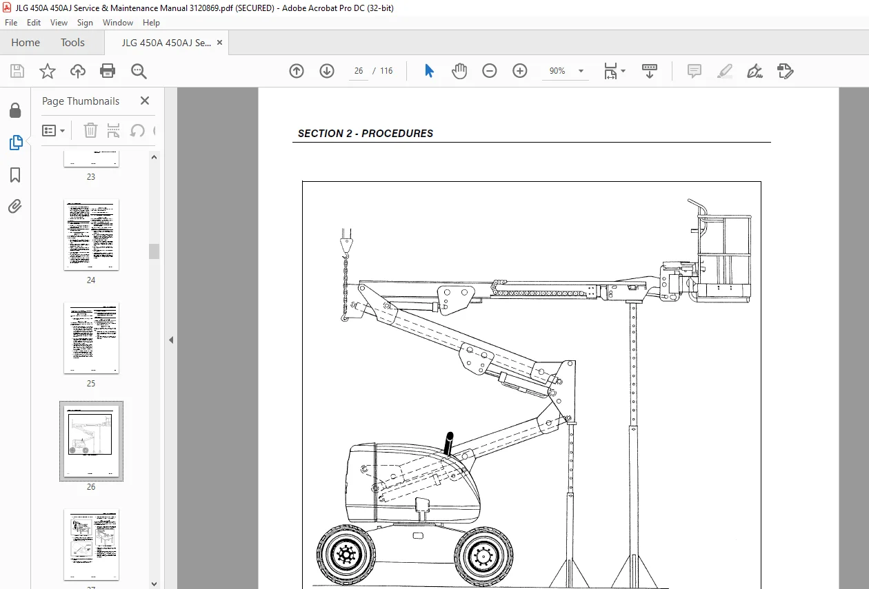
- NEVER WORK UNDER AN ELEVATED BOOM UNTIL BOOM HAS BEEN SAFELY RESTRAINED FROM ANY MOVEMENT BY BLOCKING OR OVERHEAD SLING, OR BOOM SAFETY PROP HAS BEEN ENGAGED.
- BEFORE MAKING ADJUSTMENTS, LUBRICATING OR PERFORMING ANY OTHER MAINTENANCE, SHUT OFF ALL POWER CONTROLS.
- BATTERY SHOULD ALWAYS BE DISCONNECTEDDURING REPLACEMENT OF ELECTRICAL COMPONENTS
- KEEP ALL SUPPORT EQUIPMENT AND ATTACHMENTS STOWED IN THEIR PROPER PLACE.
- USE ONLY APPROVED, NONFLAMMABLE CLEANING SOLVENTS.
IMAGES PREVIEW OF THE MANUAL:
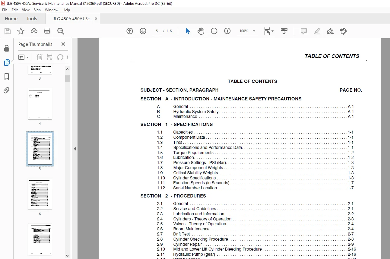
TABLE OF CONTENTS:
JLG 450A 450AJ Service & Maintenance Manual 3120869 – PDF DOWNLOAD
SECTION A – INTRODUCTION – MAINTENANCE SAFETY PRECAUTIONS
A General A-1
B Hydraulic System Safety A-1
C Maintenance A-1
SECTION 1 – SPECIFICATIONS
1 1 Capacities 1-1
1 2 Component Data 1-1
1 3 Tires 1-1
1 4 Specifications and Performance Data 1-1
1 5 Torque Requirements 1-2
1 6 Lubrication 1-2
1 7 Pressure Settings – PSI (Bar) 1-3
1 8 Major Component Weights 1-3
1 9 Critical Stability Weights 1-3
1 10 Cylinder Specifications 1-3
1 11 Function Speeds (in Seconds) 1-7
1 12 Serial Number Location 1-7
SECTION 2 – PROCEDURES
2 1 General 2-1
2 2 Service and Guidelines 2-1
2 3 Lubrication and Information 2-2
2 4 Cylinders – Theory of Operation 2-3
2 5 Valves – Theory of Operation 2-4
2 6 Boom Maintenance 2-4
2 7 Drift Test 2-7
2 8 Cylinder Checking Procedure 2-8
2 9 Cylinder Repair 2-9
2 10 Mid and Lower Lift Cylinder Bleeding Procedure 2-16
2 11 Hydraulic Pump (gear) 2-16
2 12 Swing Bearing 2-23
2 13 Worm gear 2-27
2 14 Boom Synchronizing Procedure 2-27
2 15 Extend-A-Reach 2-28
2 16 Adjustment Procedure For Lockout Valve 2-28
2 17 Torque Hub (Prior to S/N 39594) 2-29
2 18 Torque Hub (S/N 39594 to Present) 2-34
2 19 Drive Brake (Ausco) 2-45
2 20 Boom Limit Switches 2-48
2 21 Lift Up and Platform Level Down Disable Switch 2-48
2 22 Throttle Checks and Adjustments – Deutz Engine 2-49
2 23 Drive and Steer Controller 2-51
2 24 Lift and Swing Controller 2-53
2 25 Function Control 2-53
2 26 Tilt Alarm Switch 2-55
2 27 Pressure Setting Procedures 2-55
2 28 Hydraulic Component Start-Up Procedures and Recommendations 2-59
2 29 Semi-Track 2-61
2 30 Preventive Maintenance and Inspection Schedule 2-63
3 1 General 3-1
3 2 Troubleshooting 3-1
3 3 Hydraulic Circuit Checks 3-1
LIST OF FIGURES
FIGURE NO TITLE PAGE NO
1-1 Lubrication Diagram 1-4
1-2 Serial Number Locations 1-7
1-3 Torque Chart 1-8
2-1 Location of Components – Boom Removal 2-4
2-2 Location of Components – Removal of Telescope Cylinder 2-5
2-3 Location of Components – Front Wear Pads 2-6
2-4 Boom Prop Configuration 2-10
2-5 Cylinder Barrel Support 2-11
2-6 Capscrew Removal 2-11
2-7 Cylinder Rod Support 2-11
2-8 Tapered Bushing Removal 2-12
2-9 Gar-Max Bearing Installation 2-12
2-10 Rod Seal Installation 2-13
2-11 Wiper Seal Installation 2-13
2-12 Installation of Head Seal Kit 2-13
2-13 Piston Seal Kit Installation 2-14
2-14 Tapered Bushing Installation 2-14
2-15 Seating the Tapered Bearing 2-15
2-16 Poly-Pak Piston Seal Installation 2-15
2-17 Rod Assembly Installation 2-15
2-19 Swing Bearing Feeler Gauge Check 2-23
2-18 Swing Bearing Installation 2-24
2-20 Swing Bearing Tolerance Measuring Point 2-25
2-21 Swing Bearing Torquing Sequence 2-26
2-22 Synchronizing Valve 2-27
2-23 Extend-A-Reach 2-28
2-24 Front Axle 2-29
2-25 Ring Gear/Cover 2-29
2-26 Carrier 2-30
2-27 Torque Hub (Prior to S/N 39594) – Exploded View 2-31
2-28 Torque Hub (Prior to S/N 39594) – Cutaway View 2-32
2-29 Torque Hub (S/N 39594 to Present) – Cutaway View 2-35
2-30 Cluster Gear Punch Marks 2-43
2-31 Drive Brake (Ausco) 2-46
2-32 Switch Adjustment 2-48
2-33 Functional Check 2-48
2-34 Addco Adjustments – Deutz 2-49
2-35 Drive and Steer Adjustment 2-52
2-36 Lift and Swing Adjustment 2-53
2-37 Function Control Card Adjustment 2-54
2-38 Tilt Switch Adjustment 2-55
2-39 Main Valve (Proportional Controls) – Sheet 1 2-56
2-40 Main Valve (Proportional Controls) – Sheet 2 2-57
2-41 Valve Location – Chassis 2-58
3-1 Electrical Components Installation – Sheet 1 3-20
3-2 Electrical Components Installation – Sheet 2 3-21
3-3 Electrical Schematic – Boom, Turntable, Chassis – Deutz – Sheet 1 3-22
3-4 Electrical Schematic – Boom, Turntable, Chassis – Deutz – Sheet 2 3-23
3-5 Electrical Schematic – Platform -Deutz – Sheet 1 3-24
3-6 Electrical Schematic – Platform -Deutz – Sheet 2 3-25
3-7 Hydraulic Schematic – Proportional Controls 3-26
1-1 Torque Requirements 1-2
1-2 Hydraulic Oil 1-2
1-3 Lubrication Specifications 1-2
1-4 Mobil EAL Envirosyn H 46 Specs 1-2
1-5 Major Component Weights 1-3
1-6 Critical Stability Weights 1-3
1-7 Cylinder Specifications 1-3
1-8 Lubrication Chart 1-5
2-1 Cylinder Head and Tapered Bushing Torque Specifications 2-16
2-2 Holding Valve Torque Specification 2-16
2-3 Hydraulic Pump Bolt Torque Chart 2-22
2-4 Position Controller Truth Table 2-49
2-5 Adjustment Chart 2-62
2-6 Preventive Maintenance and Inspection Schedule 2-64
3-1 Platform Assembly – Troubleshooting 3-2
3-2 Boom Assembly – Troubleshooting 3-3
3-3 Turntable Assembly – Troubleshooting 3-8
3-4 Chassis Assembly – Troubleshooting 3-9
3-5 Hydraulic System – Troubleshooting 3-15
3-6 Electrical System – Troubleshooting 3-18
Need help? Contact: [email protected]
PLEASE NOTE:
- This is the SAME exact manual used by your dealers to fix your vehicle.
- The same can be yours in the next 2-3 mins as you will be directed to the download page immediately after paying for the manual.
- Any queries / doubts regarding your purchase, please feel free to contact [email protected]
S.M