JLG 510AJ Articulating Boom Lift Service Manual Repair Maintenance Technical PDF
Original price was: $95.00.$29.95Current price is: $29.95.
Official JLG service and maintenance manual for 510AJ articulating boom lift. This comprehensive 402-page technical manual provides complete troubleshooting procedures, hydraulic and electrical schematics, component disassembly/assembly instructions, JLG Control System diagnostics, engine maintenance (Deutz/Perkins), torque hub service, and boom maintenance for articulated aerial work platforms. Includes detailed coverage of drive motors, swing bearings, hydraulic cylinders, and DGC diagnostic trouble codes.
Description
JLG 510AJ Articulating Boom Lift Service Manual Repair Maintenance Technical – PDF DOWNLOAD
DESCRIPTION
JLG 510AJ Articulating Boom Lift – Complete Service and Maintenance Manual
This is the official JLG service manual (Part No. 3121181, August 2014 Revision) for the 510AJ articulating boom aerial work platform, providing comprehensive technical documentation for professional servicing, troubleshooting, and maintenance of articulated boom lifts used in construction, industrial facilities, and facility maintenance operations.
📋 FILE DETAILS
- Manual Title: Service and Maintenance Manual – Model 510AJ
- Part Number: P/N 3121181
- Publication Date: August 2014
- Revision History: Originally issued January 2003, revised through August 2014
- Total Pages: 402 pages
- PDF Quality: High-resolution professional technical manual
- Language: English
- Manufacturer: JLG Industries, Inc.
🏗️ JLG 510AJ SPECIFICATIONS
Performance Data:
- Maximum Platform Height: 51.8 feet (15.81 meters)
- Working Height: Approximately 57.8 feet (17.6 meters)
- Horizontal Outreach: Maximum forward reach capability
- Platform Capacity: 500 lbs (230 kg)
- Platform Size: Standard JLG platform
Chassis Specifications:
- Drive System: 4WD with torque hub drive
- Engine Options: Deutz diesel / Perkins diesel
- Fuel Capacity: 27 gallons (102 liters); 23.6 gal. (89 liters) usable
- Hydraulic Oil Capacity: As required (A/R) – multiple reservoirs
- Oscillating Axle: With lockout system
- Swing Bearing: Continuous 360° rotation
Engine Specifications:
- Deutz Engine: 4-cylinder diesel, 10 qt. (9.4 L) oil capacity
- Perkins Engine: Alternative 4-cylinder diesel option
- Oil Capacity with Filter: 10 quarts (9.4 liters)
📖 COMPREHENSIVE TABLE OF CONTENTS
Section A: Introduction – Maintenance Safety Precautions (Pages A-1 to A-2)
General Safety:
- Maintenance personnel qualifications and safety responsibilities
- Machine modification restrictions
- Hydraulic system safety protocols (high-pressure warnings)
- General maintenance precautions and safety requirements
Critical Safety Requirements:
- Replacement parts specifications (identical or equivalent only)
- Refueling safety and no-smoking requirements
- Personal protective equipment requirements
- Working under elevated booms safety procedures
- Power shutdown procedures before maintenance
- Battery disconnect requirements
- Approved cleaning solvents only
Section 1: Specifications (Pages 1-1 to 1-13)
1.1 Capacities:
- Fuel tank specifications
- Hydraulic oil reservoir capacity
- Engine oil capacity
- Battery specifications
1.2 Tires:
- Tire size and inflation specifications
- Tire replacement requirements
1.3 Engine:
- Deutz engine specifications
- Perkins engine specifications
- Performance parameters
1.4 Specifications and Performance Data:
- Dimensional data (height, width, length)
- Reach specifications with diagrams
- Chassis specifications
- Weight distribution
1.5 Function Speeds:
- Boom lift speed specifications
- Boom lower speed
- Telescope extend/retract speeds
- Drive speed (stowed and elevated)
- Platform rotation speed
- Swing speed
- Machine orientation for speed testing
1.6 Torque Requirements:
- Complete torque charts (5 sheets):
- SAE fastener torque specifications (Sheets 1-3)
- Metric fastener torque specifications (Sheets 4-5)
- Specialized torque requirements for critical components
1.7 Lubrication:
- Hydraulic oil specifications and recommendations
- Temperature-based oil selection charts
- Multipurpose grease specifications
- Engine oil specifications (API classifications)
1.8 Operator Maintenance:
- Daily/weekly/monthly lubrication diagram
- Grease point locations
- Fluid level check procedures
- Filter replacement intervals
1.9 Major Component Weights:
- Weight specifications for component removal/installation
1.10 Pressure Settings:
- Hydraulic system pressure specifications for all circuits
1.11 Serial Number Location:
- Machine identification plate locations
Section 2: General (Pages 2-1 to 2-11)
2.1 Machine Preparation, Inspection, and Maintenance:
- Pre-start inspection procedures
- Pre-delivery inspection requirements
- Frequent inspection protocols
- Annual machine inspection checklist
- Preventative maintenance schedules
2.2 Service and Guidelines:
- Safety and workmanship standards
- Cleanliness requirements during service
- Component removal and installation best practices
- Disassembly and reassembly procedures
- Pressure-fit parts handling
- Bearing installation and removal
- Gasket replacement procedures
- Bolt usage and torque application
- Hydraulic lines and electrical wiring service
- Battery service and maintenance
2.3 Lubrication Information:
- Hydraulic system oil specifications
- Oil change procedures and intervals
- Cylinder drift test procedures
- Platform drift testing
- Temperature specifications for engines (Deutz and Perkins)
2.4 Pins and Composite Bearing Repair Guidelines:
- Wear tolerance specifications
- Replacement criteria
2.5 Welding on JLG Equipment:
- Approved welding procedures
- Safety precautions
- Structural integrity requirements
Section 3: Chassis and Turntable (Pages 3-1 to 3-154)
3.1 Tires & Wheels:
- Tire inflation specifications
- Tire damage assessment
- Tire replacement procedures
- Wheel replacement and installation
3.2 Torque Hub (Machines Built Before S/N 1300000064):
- Roll, leak, and brake testing procedures
- Bolt tightening and torquing specifications
- Complete disassembly procedures:
- Main disassembly (21 detailed steps)
- Input carrier disassembly
- Output carrier disassembly
- Housing-spindle disassembly
- Spindle-brake disassembly
- Assembly procedures with torque specifications
- Integral brake check procedures
3.3 Torque Hub (Machines Built After S/N 1300000064):
- Roll and leak testing
- Bolt torquing procedures
- Oil information and specifications
- Main disassembly for “B” drives
- Hub-spindle, cover, and carrier disassembly/assembly
- Tool list for torque hub service
3.4 Re-Aligning Torque Hub Input Coupling:
- Alignment equipment required
- Step-by-step alignment procedures
3.5 Drive Motor:
- Drive motor description and function
- Shaft seal replacement procedures
- Loop flushing valve service
- Troubleshooting guide
- Complete disassembly procedures (detailed steps)
- Inspection criteria for all components
- Assembly procedures with torque values
- Initial start-up procedures after rebuild
3.6 Adjustment Procedure for Lockout Valve:
- Valve adjustment specifications
3.7 Oscillating Axle Bleeding and Lockout Test:
- Lockout cylinder bleeding (early cylinders)
- Lockout cylinder bleeding (ram cylinders)
- Oscillating axle lockout test procedures
3.8 Swing Bearing:
- Swing bearing description
- Removal procedures
- Disassembly instructions
- Assembly and installation
- Turntable bearing mounting bolt condition check
- Wear tolerance specifications
- Swing bearing torque sequence diagram
- Torque value specifications
3.9 Generator:
- 250-hour maintenance procedures
- 500-hour maintenance requirements
- Overload protection testing
- Brush inspection and replacement
- Slip ring cleaning procedures
3.10 Deutz Engine:
- Oil level checking procedures
- Engine oil change procedures
- Oil filter replacement
- Fuel filter replacement
- Fuel strainer cleaning
3.11 Deutz EMR 2 (S/N 1300000981 to Present):
- Engine side equipment location diagram
- Troubleshooting flow chart
- Vehicle side connection diagram
- Engine side connection diagrams (2 sheets)
- Engine plug pin identification
- Vehicle plug pin identification
- Complete EMR2 fault codes (5 sheets)
3.12 Perkins Engine General Maintenance:
- Crankcase breather replacement
- Engine oil level check
- Engine oil and filter change
- Fuel filter/water separator service
- Actuator setting procedures
- Speed sensor installation
3.13 Engine Radiator Fill Procedure:
- Procedures for Perkins and Caterpillar engines
3.14 DGC Diagnostic Support and Trouble Code Definitions:
- Section layout and abbreviations
- Fault code broadcast procedures
- Diagnostic trouble codes (DTCs)
- CAN communication protocols
- MIL (Malfunction Indicator Lamp) output
- Diagnostic calibration configuration
- Fault/DTC interaction procedures
- DBW (Drive-By-Wire) diagnostic test
3.15 Diagnostic Trouble Code Fault Descriptions (Pages 3-100 to 3-154):
Complete diagnostic procedures for all DTCs including:
- DTC 116 – ECT Higher Than Expected Stage 1
- DTC 117 – ECT/CHT Low Voltage
- DTC 118 – ECT/CHT High Voltage
- DTC 122 – TPS1 Signal Voltage Low
- DTC 123 – TPS1 Signal Voltage High
- DTC 217 – ECT Higher Than Expected 2
- DTC 219 – RPM Higher Than Max Allowed
- DTC 336 – Crank Signal Input Noise
- DTC 337 – Loss of Crank Input Signal
- DTC 521 – Oil Pressure Sender High Pressure
- DTC 524 – Oil Pressure Low
- DTC 562 – Battery Voltage Low
- DTC 563 – Battery Voltage High
- DTC 601 – Microprocessor Failure – FLASH
- DTC 604 – Microprocessor Failure – RAM
- DTC 606 – Microprocessor Failure – COP
- DTC 642 – 5 Volt External Low Voltage
- DTC 643 – 5 Volt External High Voltage
- DTC 1612-1616 – Microprocessor Failures (RTI 1-3, A/D, interrupt)
- DTC 1625 – CAN J1939 Shutdown Request
- DTC 1626 – CAN J1939 Transmit Fault
- DTC 1627 – CAN J1939 Receive Fault
- DTC 1628 – CAN Address Conflict
- DTC 1629 – J1939 TSC1 Message Receipt Loss
- DTC 1652 – TPS1 Loss of Communications
- DTC 2111 – Unable to Reach Lower TPS
- DTC 2112 – Unable to Reach Higher TPS
- DTC 9999 – Throttle Actuator Failsafe Spring Failure
- DTC to SPN/FMI conversion table
Section 4: Boom and Platform (Pages 4-1 to 4-21)
4.1 Boom Maintenance:
- Boom assembly removal procedures
- Main boom disassembly instructions
- Component inspection criteria
- Main boom assembly procedures
- Boom installation procedures
4.2 Rotator:
- Disassembly and inspection procedures
- Assembly and testing procedures
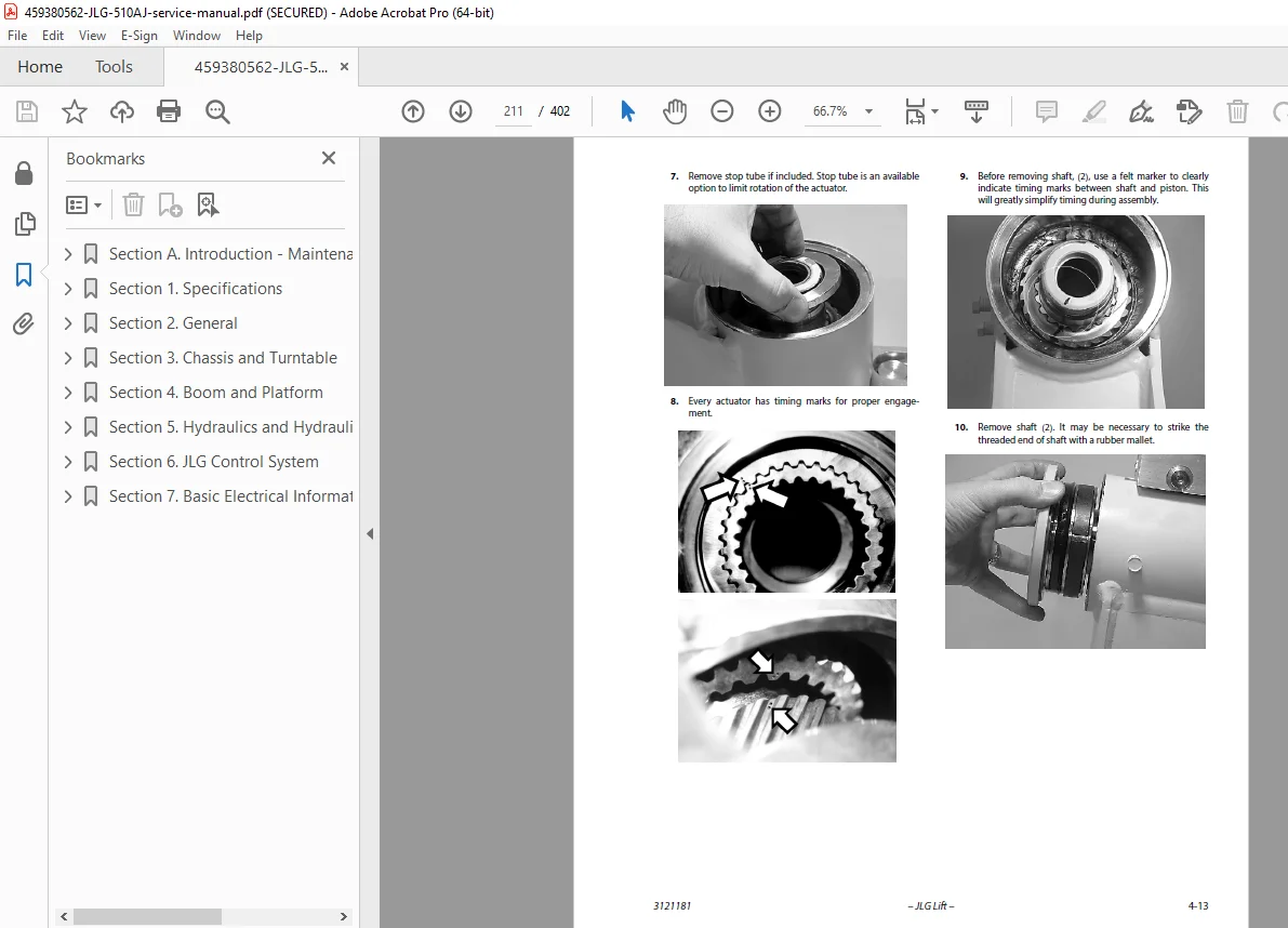
4.3 Rotary Actuator (S/N 1300006433 to Present):
- Theory of operation
- Required tools list
- Complete disassembly procedures
- Inspection criteria
- Assembly procedures
- Counterbalance valve installation
Section 5: Hydraulics and Hydraulic Schematics (Pages 5-1 to 5-53)
5.1 O-Ring Lubrication:
- Cup and brush method
- Dip method
- Spray method
- Brush-on method
5.2 Hydraulic Cylinders:
Complete service procedures for all cylinders:
- Tower Lift Cylinder – Disassembly, inspection, assembly
- Main Lift Cylinder – Complete rebuild procedures
- Master Cylinder – Platform leveling system
- Telescope Cylinder – Extension system service
- Platform Level (Slave) Cylinder – Leveling system
- Jib Lift Cylinder – Articulating jib service
- Steer Cylinder – Steering system
- Axle Lockout Cylinder (Outside Frame and Inside Frame versions)
5.3 Hydraulic Pump (Gear):
- Disassembly procedures
- Parts inspection for wear
- Reverse shaft rotation procedures
- Assembly instructions
- Placing pump back into service
5.4 Variable Pump:
- Ports and pressure gauge locations
- NFPE control information
- FNR and NFPE module removal/installation
- Control orifice service
- Charge relief valve service
- Shaft seal and shaft replacement
- Charge pump service
5.5 Hydraulic Component Start-Up Procedures:
- Initial start-up recommendations
- System bleeding procedures
5.6 Pressure Setting Procedures:
- Telescope main relief adjustment
- Steer system pressure
- Platform level up/down pressure
- Articulating jib pressure
- Proportional main relief
- Lift down pressure
- Swing pressure
Section 6: JLG Control System (Pages 6-1 to 6-53)
6.1 Introduction:
- JLG Control System overview
- System architecture
6.4 Connecting the JLG Control System Analyzer:
- Connection procedures
- Safety precautions
6.5 Using the Analyzer:
- Navigation and operation
6.6 Changing Access Level:
- Technician access levels
- Password requirements
6.7 Adjusting Parameters:
- Parameter modification procedures
6.8 Machine Setup:
- Complete machine configuration
- System calibration
6.9 Machine Personality Settings:
- Custom configuration options
- Function enable/disable
6.10 System Test:
- Test from the platform procedures
- Test from ground station procedures
Section 7: Basic Electrical Information and Electrical Schematics (Pages 7-1 to 7-9+)
7.1 General:
- Electrical system overview
7.2 Multimeter Basics:
- Grounding procedures
- Backprobing techniques
- Min/Max functions
- Polarity testing
- Scale selection
- Voltage measurement
- Resistance measurement
- Continuity measurement
- Current measurement
7.3 Applying Silicone Dielectric Compound:
- Electrical connection protection
7.4 AMP Connectors:
- Silicone compound application
- Assembly procedures
- Disassembly procedures
- Wedge lock operation
- Voltage reading service procedures
7.5 Deutsch Connectors:
- DT/DTP series assembly/disassembly
- HD30/HDP20 series assembly/disassembly
Complete Electrical Schematics:
- Detailed wiring diagrams for all systems
- Component location diagrams
- Connector pin-out diagrams
🔧 KEY SYSTEMS COVERED
Articulating Boom Technology:
- Multi-section articulated boom design
- Platform leveling system (master/slave cylinders)
- Articulating jib functionality
- Platform rotation mechanism
- Boom elevation and lowering systems
- Telescope extend/retract operation
Drive and Chassis Systems:
- Torque hub drive technology (pre and post S/N 1300000064)
- 4-wheel drive system
- Hydraulic drive motors
- Oscillating axle with lockout
- Steering cylinder and linkage
- Brake systems (integral and parking)
Hydraulic Systems:
- Variable displacement pump
- Gear pump backup
- Proportional valve control
- Load-sensing circuits
- Counterbalance valves
- Pressure relief and safety valves
- Multi-function hydraulic manifolds
JLG Control System:
- Electronic control architecture
- Hand-held analyzer diagnostics
- Machine personality settings
- Function enable/disable capability
- Parameter adjustment
- System testing procedures
Engine Systems:
- Deutz diesel engine (standard)
- Deutz EMR 2 electronic control
- Perkins diesel (alternative)
- DGC (Digital Governor Control)
- CAN bus communication (J1939 protocol)
- Comprehensive diagnostic trouble codes
Safety Systems:
- Tilt sensor and alarm
- Platform overload protection
- Function lockout systems
- Emergency lowering procedures
- Ground fault protection
👨🔧 WHO SHOULD USE THIS MANUAL
- Aerial Lift Technicians – Servicing JLG articulating boom lifts
- Equipment Rental Service Personnel – Maintaining rental fleet units
- Construction Equipment Mechanics – Repairing articulated platforms
- Facility Maintenance Technicians – In-house JLG equipment service
- Mobile Equipment Service Companies – Third-party JLG service providers
- Certified Aerial Platform Technicians – Specialized platform mechanics
- Fleet Maintenance Managers – Overseeing JLG equipment fleets
🏗️ APPLICATIONS & INDUSTRIES
JLG 510AJ articulating boom lifts are used in:
- Commercial and industrial construction sites
- Facility maintenance and building services
- Bridge and infrastructure inspection
- Sign installation and maintenance
- Tree trimming and arboriculture services
- Film and entertainment production
- Warehouse and distribution centers
- Manufacturing facilities
- Shipyards and marine facilities
- Utility and telecommunications work
- Stadium and arena maintenance
- Airport facility maintenance
⚡ CRITICAL SERVICE PROCEDURES
Torque Hub Service:
- Complete disassembly with 21-step procedure
- Bearing replacement and adjustment
- Brake disc inspection and replacement
- Seal installation with specialized tools
- Torque sequence specifications
- Leak testing procedures
Hydraulic Cylinder Rebuild:
- Seal kit replacement for all cylinders
- Piston and rod inspection
- Cylinder tube honing specifications
- Drift testing after rebuild
- Pressure testing requirements
Drive Motor Overhaul:
- Shaft seal replacement
- Cylinder barrel inspection
- Swash plate service
- Valve plate refacing
- Loop flushing valve service
- Initial start-up and break-in
Swing Bearing Service:
- Bearing race inspection
- Mounting bolt torque sequence
- Wear tolerance measurement
- Grease purging procedures
- Preload adjustment
Diagnostic Trouble Code Resolution:
- Complete DTC descriptions with causes
- Step-by-step troubleshooting procedures
- Electrical testing specifications
- Component replacement criteria
- System verification after repair
📐 REGULATORY COMPLIANCE
This manual covers equipment designed to meet:
- ANSI A92.5 Boom-Supported Elevating Work Platforms
- CSA B354.2 Self-Propelled Elevating Work Platforms
- CE marking for European Machinery Directive
- OSHA aerial platform regulations
- IPAF (International Powered Access Federation) standards
💡 WHY THIS MANUAL IS ESSENTIAL
This official JLG service manual is the authoritative technical reference containing proprietary service procedures, complete hydraulic schematics, detailed electrical diagrams, and JLG Control System diagnostics not available from any other source. With 402 pages of comprehensive technical information including complete torque hub disassembly (21 steps), all hydraulic cylinder rebuild procedures, drive motor overhaul instructions, swing bearing service, complete Deutz EMR2 and DGC diagnostic trouble code descriptions (30+ DTCs), and JLG Control System analyzer procedures, this manual enables you to maintain critical aerial work platform equipment at peak safety and performance while minimizing costly downtime. Download instantly and have immediate access to the exact hydraulic diagrams, electrical schematics, torque specifications, and diagnostic procedures you need to service JLG 510AJ articulating boom lifts with 51.8-foot platform height – essential for equipment rental companies, construction contractors, and facility maintenance departments.
Pricing Rationale: This is a comprehensive 402-page professional service manual for a sophisticated JLG articulating boom aerial work platform with 51.8-foot working height. The manual covers complex systems including electronic engine controls (Deutz EMR2 and DGC), JLG proprietary Control System with analyzer procedures, detailed torque hub service (21-step disassembly), complete hydraulic cylinder rebuild procedures for 8 different cylinders, drive motor overhaul, swing bearing service, and 30+ diagnostic trouble codes with complete troubleshooting procedures. JLG 510AJ units are high-value equipment ($75,000-$120,000) requiring specialized knowledge for service. The extensive technical diagrams, proprietary JLG Control System information, and component-level repair procedures justify premium pricing. Similar JLG articulating boom service manuals typically range from $39.95-$54.95 depending on model complexity and manual scope.