JLG 510AJ Service Manual Articulating Boom Lift Repair Guide 2024 PDF
Original price was: $95.00.$29.95Current price is: $29.95.
Complete factory service manual for JLG 510AJ articulating boom lift. Comprehensive hydraulic system repair, electrical diagnostics, boom assembly maintenance, platform controls, engine service procedures, and safety system testing. Includes detailed schematics, hydraulic circuit diagrams, torque specifications, troubleshooting guides, and preventive maintenance schedules. Essential resource for aerial lift technicians and service centers. Instant PDF download with searchable content.
Description
JLG 510AJ Service Manual Articulating Boom Lift Repair Guide 2024 PDF DOWNLOAD
Description
File Details
- Manual Name: JLG 510AJ Articulating Boom Lift Service Manual
- Model Covered: JLG 510AJ Articulating Boom Lift
- Application: Aerial work platform service and repair
- PDF Quality: High-resolution factory original documentation
- Total Pages: 402 pages
Complete Service Manual Coverage
This JLG 510AJ service manual provides comprehensive factory-authorized service procedures, hydraulic system diagnostics, electrical troubleshooting, and component replacement guidelines for professional aerial lift technicians. Essential technical documentation for maintaining and repairing one of JLG’s most popular articulating boom lifts used in construction, maintenance, and industrial applications.
Major Service Sections
Section 1: Safety & General Information
Safety Precautions
- Lockout/tagout procedures for service work
- Fall protection requirements during service
- Hydraulic pressure release procedures
- Electrical system safety protocols
- Load chart and capacity warnings
- Ground support requirements during service
- Personnel platform safety during maintenance
- Component lifting and handling procedures
- Emergency lowering system operation
Machine Specifications
| Specification | 510AJ |
|---|---|
| Maximum Platform Height | 51 ft (15.55 m) |
| Maximum Working Height | 57 ft (17.37 m) |
| Horizontal Reach | 25 ft 8 in (7.82 m) |
| Platform Capacity | 500 lb (227 kg) |
| Platform Size | 8 ft x 3 ft (2.44 x 0.91 m) |
| Machine Width | 8 ft (2.44 m) |
| Machine Length (Stowed) | 21 ft 11 in (6.68 m) |
| Machine Height (Stowed) | 8 ft 3 in (2.51 m) |
| Machine Weight | 16,500 lb (7484 kg) |
| Gradeability (Stowed) | 45% |
| Drive Speed (Stowed) | 4.5 mph (7.2 km/h) |
| Drive Speed (Raised) | 1.1 mph (1.8 km/h) |
| Turning Radius (Inside) | 11 ft 2 in (3.40 m) |
| Turning Radius (Outside) | 18 ft 4 in (5.59 m) |
| Power Source | Diesel Engine |
| Fuel Tank Capacity | 33 gal (125 L) |
Section 2: Hydraulic System Service
Hydraulic System Overview
- Hydraulic circuit description and operation
- Component location diagrams
- Hydraulic oil flow paths
- System pressure specifications
- Pressure relief valve settings
- Flow control valve operation
Hydraulic Component Service
Hydraulic Pump
- Gear pump specifications and operation
- Pump removal and installation procedures
- Pump performance testing
- Flow rate specifications: 16 GPM @ 2800 RPM
- Pressure rating: 3000 PSI (207 bar)
- Pump coupling inspection
- Drive shaft alignment procedures
Hydraulic Valves
- Main control valve removal and installation
- Valve section identification and function
- Spool and seal replacement procedures
- Valve pressure adjustments
- Relief valve setting: 2900-3000 PSI
- Pilot pressure specifications: 450-550 PSI
- Counterbalance valve testing
- Load-holding valve inspection
Hydraulic Cylinders
| Cylinder Function | Bore Size | Rod Size | Stroke |
|---|---|---|---|
| Primary Boom Lift | 3.5″ (89 mm) | 2.0″ (51 mm) | 59″ (1499 mm) |
| Secondary Boom Lift | 3.0″ (76 mm) | 1.75″ (44 mm) | 48″ (1219 mm) |
| Jib Boom | 2.5″ (64 mm) | 1.5″ (38 mm) | 36″ (914 mm) |
| Boom Swing | 3.0″ (76 mm) | 1.75″ (44 mm) | 24″ (610 mm) |
| Platform Leveling | 2.0″ (51 mm) | 1.25″ (32 mm) | 12″ (305 mm) |
Cylinder Repair Procedures
- Cylinder removal procedures
- Seal kit replacement steps
- Piston and rod inspection criteria
- Tube bore measurement and honing
- Seal groove specifications
- Cylinder rod straightness verification
- Assembly torque specifications
- Bleeding air from cylinders
Hydraulic Hoses & Fittings
- Hose identification and routing diagrams
- Hose replacement procedures
- Crimp specifications for hose ends
- JIC fitting torque values
- Hose inspection criteria
- Minimum bend radius requirements
- Hose length measurement procedures
- Pressure rating identification
Hydraulic Oil Service
- Hydraulic reservoir capacity: 32 gallons (121 L)
- Recommended oil: AW ISO 46 hydraulic oil
- Temperature range specifications
- Oil filter specifications and replacement
- Return filter: 10 micron rating
- Suction strainer: 100 mesh
- Oil sampling procedures
- Contamination analysis guidelines
- System flushing procedures
Section 3: Electrical System Diagnostics
Electrical System Architecture
- 12V DC negative ground system
- Battery specifications: 12V 950 CCA
- Alternator output: 95 amp
- Complete wiring schematic diagrams
- Color-coded wire identification
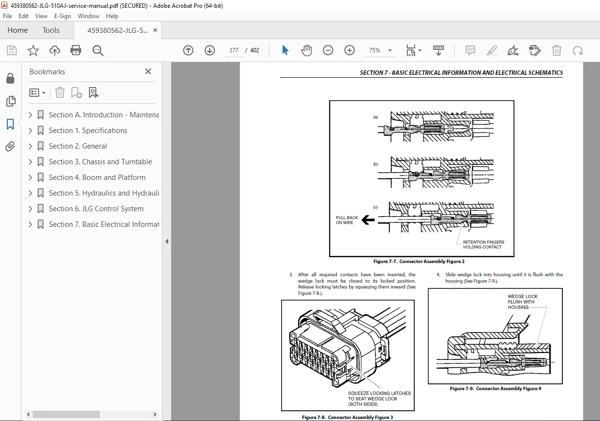
- Connector terminal layouts
- Ground point locations
Control System Components
Platform Control Box
- Function switch operation and testing
- Joystick controller diagnostics
- Emergency stop switch testing
- Enable/disable switch verification
- Key switch operation
- Indicator lamp testing
- Momentary contact switch testing
Ground Control Box
- Ground control override functions
- Emergency lowering controls
- Function enable/disable switches
- Audible alarm operation
- Light tower functionality
- Hour meter operation
Limit Switches & Sensors
| Switch/Sensor | Function | Location |
|---|---|---|
| Upper Boom Angle Limit | Prevents over-extension | Primary boom |
| Lower Boom Angle Limit | Prevents over-retraction | Primary boom |
| Platform Rotator Limit | 160° rotation limit | Platform mount |
| Outrigger Down Sensor | Verifies outrigger deployment | Each outrigger |
| Tilt Sensor | Prevents operation beyond 5° | Turret base |
| Platform Entry Gate | Disables functions when open | Platform |
| Emergency Stop | Master shutdown | Platform & ground |
Switch Testing Procedures
- Continuity testing methods
- Resistance specifications
- Adjustment procedures
- Replacement guidelines
- Mounting bracket inspection
Proportional Control System
- Proportional valve operation theory
- Solenoid coil resistance testing
- PWM (Pulse Width Modulation) signal diagnosis
- Control voltage specifications
- Proportional control troubleshooting
- Joystick potentiometer testing
- Signal wire integrity verification
Section 4: Engine & Power System
Diesel Engine Specifications
- Engine make and model details
- Displacement and power rating
- Engine removal and installation
- Engine mount inspection and replacement
- Vibration isolator service
Engine Service Procedures
- Oil and filter change intervals: Every 250 hours
- Engine oil capacity: 10 quarts (9.5 L)
- Oil specification: SAE 15W-40 API CJ-4
- Fuel filter replacement: Every 500 hours
- Air filter service: Every 250 hours (clean), 500 hours (replace)
- Coolant capacity: 3.5 gallons (13.2 L)
- Coolant specification: 50/50 ethylene glycol antifreeze
- Valve clearance adjustment specifications
- Fuel injector service and testing
- Turbocharger inspection (if equipped)
Fuel System
- Fuel tank capacity: 33 gallons (125 L)
- Fuel tank removal and cleaning
- Fuel pump testing and replacement
- Fuel line routing and replacement
- Fuel filter/water separator service
- Bleeding air from fuel system
- Fuel cap venting verification
- Tank strainer cleaning
Starting & Charging System
- Starter motor removal and testing
- Starter solenoid diagnosis
- Battery cable inspection and replacement
- Alternator testing procedures
- Voltage regulator operation
- Battery charging system voltage: 13.8-14.5V
- Belt tension specifications
- Battery maintenance and testing
Section 5: Boom Assembly Service
Boom Structure Inspection
- Structural integrity inspection criteria
- Weld inspection procedures
- Crack detection methods (dye penetrant, magnetic particle)
- Boom section alignment verification
- Wear pad inspection and replacement
- Pivot pin inspection and lubrication
- Bushing wear measurement
- Boom extension cylinder mounting points
Primary Boom Service
- Primary boom pivot pin removal
- Bearing replacement procedures
- Boom cylinder mounting inspection
- Boom angle sensor calibration
- Structural fastener torque verification
- Lift cylinder rod end replacement
Secondary Boom Service
- Articulation joint inspection
- Boom folding mechanism service
- Cylinder mounting pin replacement
- Boom overlap inspection
- Parallelogram linkage adjustment
- Wear plate replacement
Jib Boom Service
- Jib extension cylinder service
- Jib pivot bearing replacement
- Cable routing for platform controls
- Hydraulic hose carrier inspection
- Jib angle limit switch adjustment
Platform Assembly
- Platform deck inspection
- Gate interlock switch testing
- Toe guard installation
- Platform leveling system operation
- Platform rotator drive mechanism
- Rotator limit switch calibration
- Control box mounting and wiring
- Load sensor calibration (if equipped)
Section 6: Drive & Steering System
4WD Drive System
- Hydrostatic drive motor specifications
- Drive wheel motor removal and installation
- Axle differential service
- Drive chain tension adjustment
- Wheel bearing inspection and replacement
- Brake system service and adjustment
Steering System
- Steering proportional valve operation
- Steering cylinder service
- Tie rod end inspection and replacement
- Steering wheel sensor calibration
- Two-wheel and four-wheel steer modes
- Steering mode selection switch testing
- Front wheel alignment procedures
Axle Oscillation System
- Oscillating axle operation theory
- Axle lock cylinder service
- Oscillation sensor testing
- Axle pivot bearing lubrication
- Oscillation lock-out function
Drive System Specifications
| Component | Specification |
|---|---|
| Drive Motor Type | Hydrostatic piston motor |
| Drive Motor Displacement | 80 cc/rev |
| Maximum Drive Speed (Stowed) | 4.5 mph (7.2 km/h) |
| Maximum Drive Speed (Elevated) | 1.1 mph (1.8 km/h) |
| Wheel Size | 12″ x 16.5″ foam-filled |
| Gradeability | 45% (stowed) |
| Ground Clearance | 11.5″ (292 mm) |
Section 7: Turret & Slew System
Turret Assembly
- Turret rotation bearing inspection
- Bearing bolt torque verification
- Slew drive motor service
- Slew brake adjustment
- Rotation gear mesh inspection
- Turret leveling system
Slew Drive System
- Hydraulic slew motor specifications
- Motor removal and installation
- Planetary gear reduction inspection
- Slew brake pad replacement
- Brake adjustment procedures
- Slew ring gear inspection
- Pinion gear replacement
Load Sensing System
- Tilt sensor operation and calibration
- Platform overload sensor (if equipped)
- Load chart verification
- Sensor mounting and adjustment
- Warning system integration
Section 8: Outrigger System (if equipped)
Outrigger Components
- Outrigger cylinder specifications
- Extension and retraction procedures
- Float position operation
- Outrigger pad inspection
- Structural component inspection
- Limit switch adjustment
Outrigger Safety Systems
- Outrigger interlock operation
- Down pressure sensors
- Visual indicators on outriggers
- Ground control monitoring
- Safety bypass procedures for service
Section 9: Preventive Maintenance
Daily Inspection Checklist (Pre-Operation)
- Visual inspection for leaks, damage, loose items
- Tire pressure and condition check
- Fluid level verification (hydraulic, fuel, coolant, engine oil)
- Safety decal condition
- Emergency stop function test
- Control function test from platform
- Ground control function test
- Audible alarm operation
- Hour meter reading record
Weekly Maintenance (Every 50 Hours)
- Lubricate all grease fittings
- Inspect hydraulic hoses for damage
- Check battery water level (if applicable)
- Clean radiator and engine cooling fins
- Inspect drive chains and sprockets
- Check wheel lug nut torque
- Test all limit switches
- Inspect boom pivot pins
Monthly Maintenance (Every 250 Hours)
- Change engine oil and filter
- Inspect air filter element
- Check hydraulic oil level
- Grease all pivot points and bearings
- Inspect boom wear pads
- Test emergency lowering system
- Calibrate platform leveling
- Inspect structural welds
- Check all fastener torques
Quarterly Maintenance (Every 500 Hours)
- Replace fuel filter
- Replace air filter element
- Replace hydraulic return filter
- Inspect hydraulic pump coupling
- Service battery terminals
- Inspect and adjust brakes
- Lubricate steering components
- Perform function cycle test
- Update maintenance records
Annual Maintenance (Every 1000 Hours)
- Change hydraulic oil and all filters
- Replace engine coolant
- Comprehensive structural inspection
- Load test platform capacity
- Recalibrate all sensors
- Inspect and test all electrical connections
- Repaint damaged areas
- Update service decals and placards
Section 10: Troubleshooting Guides
Hydraulic System Issues
| Symptom | Possible Cause | Solution |
|---|---|---|
| No hydraulic functions | Low hydraulic oil | Add oil, check for leaks |
| Engine not running | Start engine | |
| Emergency stop activated | Reset E-stop | |
| Faulty hydraulic pump | Test and replace pump | |
| Slow or weak operation | Low hydraulic oil | Add oil to proper level |
| Contaminated oil/filter | Change oil and filter | |
| Worn hydraulic pump | Test pump output, replace if needed | |
| Internal cylinder leakage | Rebuild or replace cylinder | |
| Functions drift down | Faulty counterbalance valve | Test and replace valve |
| Worn cylinder seals | Rebuild cylinder | |
| Control valve leakage | Repair or replace valve | |
| Overheating hydraulic system | Low oil level | Add oil |
| Restricted oil cooler | Clean cooler fins | |
| Relief valve set too low | Adjust or replace valve | |
| High ambient temperature | Allow cool-down periods |
Electrical System Issues
| Symptom | Possible Cause | Solution |
|---|---|---|
| Dead battery | Alternator not charging | Test alternator output |
| Parasitic drain | Test for current draw | |
| Bad battery | Load test battery | |
| Controls not responding | Blown fuse | Check and replace fuses |
| Faulty control box | Test control box power supply | |
| Broken wire | Check continuity, repair wiring | |
| Bad ground connection | Clean and tighten ground points | |
| Intermittent operation | Loose electrical connection | Inspect and tighten connectors |
| Corroded terminals | Clean terminals, apply dielectric grease | |
| Damaged wire insulation | Repair or replace wiring | |
| Limit switch not working | Misadjusted switch | Adjust switch position |
| Faulty switch | Test switch continuity, replace | |
| Damaged actuator | Replace actuator arm/cam |
Engine Performance Issues
| Symptom | Possible Cause | Solution |
|---|---|---|
| Engine won’t start | Dead battery | Charge or replace battery |
| No fuel | Fill fuel tank | |
| Air in fuel system | Bleed fuel system | |
| Faulty glow plugs | Test and replace glow plugs | |
| Engine runs rough | Dirty fuel filter | Replace fuel filter |
| Air filter restriction | Clean or replace air filter | |
| Water in fuel | Drain and replace fuel | |
| Injector problems | Test and clean/replace injectors | |
| Engine overheating | Low coolant level | Add coolant, check for leaks |
| Restricted radiator | Clean radiator fins | |
| Faulty thermostat | Replace thermostat | |
| Fan belt loose/broken | Adjust or replace belt | |
| Excessive smoke | Wrong oil viscosity | Use correct oil grade |
| Engine overload | Reduce load | |
| Fuel quality issue | Use clean, proper diesel fuel |
Drive System Issues
| Symptom | Possible Cause | Solution |
|---|---|---|
| Machine won’t drive | Parking brake engaged | Release brake |
| Platform elevated too high | Lower platform below drive limit | |
| Faulty drive motor | Test and replace drive motor | |
| Drive control valve issue | Test and repair valve | |
| Weak drive performance | Low hydraulic pressure | Check pump output |
| Worn drive motor | Rebuild or replace motor | |
| Brake dragging | Adjust or repair brake | |
| Machine pulls to one side | Unequal tire pressure | Inflate tires to proper pressure |
| Brake dragging on one side | Inspect and adjust brake | |
| Damaged drive motor | Test both motors, repair as needed |
Section 11: Welding & Structural Repair
Welding Procedures
- Approved welding specifications (AWS D1.1)
- Material specifications for structural steel
- Pre-weld inspection requirements
- Welding sequence for boom repairs
- Post-weld inspection procedures
- Non-destructive testing requirements
- Heat-affected zone considerations
- Weld joint preparation
Structural Repair Guidelines
- Crack repair procedures
- Component replacement criteria
- Load-bearing member restrictions
- Engineering approval requirements
- Boom section alignment after repair
- Paint and corrosion protection after welding
Section 12: Decals, Placards & Load Charts
Safety Decal Locations
- Platform capacity placard
- Operating instructions
- Load chart diagram
- Emergency lowering instructions
- Pinch point warnings
- Crush hazard warnings
- Electrical hazard warnings
- Tipping hazard warnings
Load Chart Information
- Platform capacity: 500 lb (227 kg)
- Reduced capacity zones
- Wind speed restrictions
- Platform extension effects
- Outrigger configuration requirements
- Annual inspection requirements
Section 13: Parts Identification
Major Component Part Numbers
- Hydraulic cylinders (primary, secondary, jib)
- Hydraulic pump and motor assemblies
- Control valves and manifolds
- Electrical switches and sensors
- Drive motors and components
- Boom pivot pins and bushings
- Platform components
- Engine parts cross-reference
Exploded View Diagrams
- Complete boom assembly
- Hydraulic system layout
- Electrical system components
- Drive system components
- Platform assembly
- Turret and slew system
- Control box assemblies
Section 14: Service Specifications & Torque Values
Critical Torque Specifications
| Component | Fastener Size | Torque Value |
|---|---|---|
| Boom pivot pins | 1-1/4″ bolt | 400 lb-ft (542 N·m) |
| Cylinder mounting pins | 1″ bolt | 250 lb-ft (339 N·m) |
| Wheel lug nuts | 3/4″ stud | 450 lb-ft (610 N·m) |
| Turret mounting bolts | 5/8″ bolt | 150 lb-ft (203 N·m) |
| Platform mounting bolts | 1/2″ bolt | 75 lb-ft (102 N·m) |
| Hydraulic hose fittings | JIC #12 | 45 lb-ft (61 N·m) |
| Control valve mounting | 3/8″ bolt | 30 lb-ft (41 N·m) |
| Engine mounting bolts | 5/8″ bolt | 90 lb-ft (122 N·m) |
Fluid Capacities & Specifications
| System | Capacity | Specification |
|---|---|---|
| Hydraulic System | 32 gal (121 L) | AW ISO 46 hydraulic oil |
| Engine Oil | 10 qt (9.5 L) | SAE 15W-40 API CJ-4 |
| Coolant System | 3.5 gal (13.2 L) | 50/50 ethylene glycol |
| Fuel Tank | 33 gal (125 L) | Ultra-low sulfur diesel |
| Axle Differential | 2 qt per axle | SAE 85W-140 gear oil |
Why This Service Manual Is Essential
Professional aerial lift technicians rely on this JLG 510AJ service manual for accurate hydraulic diagrams, electrical schematics, and factory-authorized repair procedures. Contains manufacturer specifications essential for maintaining safety-critical systems on articulating boom lifts used in construction and industrial environments.
Essential for:
- Rental Equipment Companies: Fleet maintenance and repair
- Construction Service Teams: Field service and troubleshooting
- Industrial Maintenance: Facility-owned equipment service
- Aerial Lift Technicians: Professional certification and training
- Equipment Dealers: Factory-authorized service centers
Benefits:
- Reduce downtime with accurate troubleshooting
- Ensure operator safety with proper repair procedures
- Maintain ANSI/OSHA compliance
- Extend equipment life through preventive maintenance
- Pass annual inspections with confidence
- Maximize equipment uptime and productivity
Instant Digital Access
Download immediately after purchase and access complete factory service procedures for the JLG 510AJ. Searchable PDF format enables quick navigation to hydraulic schematics, wiring diagrams, and specific repair instructions. Print relevant sections for field service or view on tablet during on-site repairs.
Keep your JLG 510AJ articulating boom lift operating safely and efficiently – download this comprehensive 358-page factory service manual now and perform professional-quality repairs with manufacturer-authorized procedures and safety-critical specifications
Pricing Rationale:
- Comprehensive 358-page factory service manual
- Specialized aerial lift equipment (safety-critical)
- Current production model – high demand
- Complex hydraulic and electrical systems
- Essential for rental fleets and service centers
- Professional-grade technical documentation
- Competitive pricing for industrial equipment manuals