JLG 60HT 60HTH Parts Manual (3120258) – PDF DOWNLOAD (Eng)
Original price was: $70.00.$22.95Current price is: $22.95.
JLG 60HT 60HTH Parts Manual (3120258) – PDF DOWNLOAD
Description
JLG 60HT 60HTH Parts Manual (3120258) – PDF DOWNLOAD
TABLE OF CONTENTS:
JLG 60HT 60HTH Parts Manual (3120258) – PDF DOWNLOAD
TABLE OF CONTENTS
SUBJECT
SI CTION I ·- RECOMMENDED SERVICE PARTS STOCK ,
SECTION 2 – ILLUSTRATED PARTS LIST
Boom and Limit Switches Installations
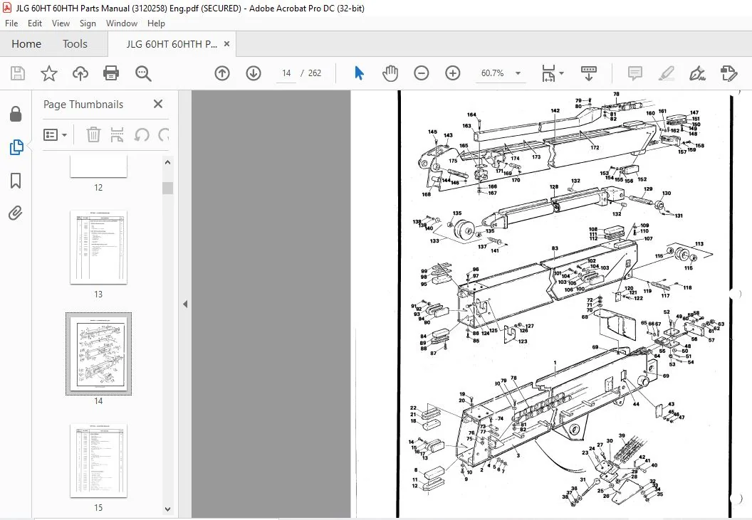
Boom Assembly
Telescope Cylinder Assembly
Slave Cylinder Assembly
Slave Cylinder Assembly
Master Cylinder Assembly
Lift Cylinder Assembly
Boom Wipers Installation
Boom Prop Installation
Steering Tube Support Installation
Platforms and Control Stands Assemblies and Installations
Hyciraulic Motor Assembly
Platform Control Box Assembly (Vickers Valves and OEM Controllers)
Platform Control Box Assembly (Vickers Valves, PO Conti oilers and
Proportional Telescopli)
Platform Control Hox Assembly (PO Controllers and Non-Proportional
TelPscope)
Platform 1::::ontrol Box Assembly (Racine Valves)
Ground Controls Assembly and Installation
Ground Controls As’;ernbly and Installation
Control Valves Installations – f-1acino
Proportional Control Valve Assembly (Racine)
Worl<ing Sections • Proportional Control Valve (Racine)
Inlet Sectio11 l’roportiorrnl r.ontrul Vnlvn /llacine).
Servo Section·· Proportional Crrntrol \/alvn /Racimi)
Control Valves Installations · Vickr;rs
Control Valve AsseinlJly ·· Vickers
Control Valve – Racirw Flan\J· f3an9
Ennine and 1″:omponenls Assernhly and l11stallation ·· For,! I. SC,-42′.i Gas
Dt1ill Ft1el lnstallillion Forr1
Precision f3overnnr lnstilllation ·· Ford
Adoco Thrnltle l11stallation – Ford
AC <1ener;itor Installation·· Ford
Rr,n10te Oil F’iltor illld Drain • Ford
Enginr1 and Components Ass1irnl)ly and Installation DA11lz l’.lL 912 Diesnl
Ftwl Sh11t Off :ind Hiqh L11Jine Installations Deutz
Adee,> Throttlu Components lnstdllation DE;utz
AC Cnnorator Installation·· Drn1L:
Enninu and Cornpu1ie11ts Assembly ancl l11stallatio11 – Wiscurn,i11 \/46!1D C,as
Oxy r.atalyst P111itior 11 i,3tallatio11
Mai11 Purnp Ass1m1hl/ ·· ne,11 (Witho111 Pnrtnd End).
Main P11111p Assrnnhly · Gear (With 1″011,id I nci)
Main Pu111p Asse111hl/ r:i1,;ton
Gear P11rnp AssPrnhly
Tank lnstallc1lion (l1aci1w)
rank lnslallc1tinn (\/ickFJtS)
I P fias Tanks lns1;1llation
Hood lnstallatio11 c111d Accdssnr1,–, /St,rnda1d)
1 lnod l11stallation a11il Accessories (7′ x i’ Vick1:1S ,rnrl 601 Ill li
Tilt lndi1..alCH l,1st:illatin11
Oil Coolm ln:c;lall1t11>11
T,irnlabli!S :ind Swi11n (;0111p1JllDllfS Assenl·l I, 1,·S and lnstall,ilI1111′.,
Swinq D1 ive f,:1, ,tor A–,,;l,mhly
TITLE
Swing Drive Brake Assembly (Ausco)
Swing Drive Brake Assembly (Mico)
Swing Drive Hub Assembly
Frame, Steering and Drive Components, Assemblies and Installations – Fixed Axle
(Standard and 7′ x 7′)
Frame, Steering and Drive Components, Assemblies and Installations – Fixed Axle
(Vickers and 60HTH)
Frame, Steeering and Drive Components, Assemblies and Installations –
Oscillating Axle (60HTH)
Frame, Steering and Drive Components, Assemblies and Installations – 4WD
Drive Motor (Standard and 7′ x 7′ Fixed Axle)
Drive Motor (Vickers Fixed, 60HTH Fixed and Oscillating and 4WD Rear)
Drive Motor (4WD Front)
Drive Brake – Ausco (Fixed and Oscillating Axles Except Vickers and 4WD)
Drive Brake – Mico (Fixed and Oscillating Axle Except Vickers and 4WD)
Drive Brake (Vickers and 4WD)
Drive Reducer (Vickers Fixed and 60HTH Fixed and Oscillating)
Drive Torque Hub
Steer Cylinder Assemblies
Lockout Cylinder Assemblies
Valves Installation (Frame Mounted)
Lockout Valve Assembly
Tow Package Installation
Nameplates and Decals Installations
Axle Lockout Circuit. Hydraulic
Drive Circuit, Hydraulic (Standard and 7′ x 7′)
Drive Circuit. Hydraulic (Vickers and 60HTH)
Drive Circuit, Hydraulic (4WD)
Level Circuit, Hydraulic
Lift Circuit, Hydraulic (Standard and 7′ x 7′)
Lift Circuit, Hydraulic (Vickers and 60HTH)
Manual Descent Circuit, Hydraulic
Pump Circuit, Hydraulic (Standard and 7′ x 7′ With Gear Pump and Without
Steering Wheel)
Pump Circuit, Hydraulic (Standard and 7′ x 7′ With Gear Pump and With
Steering Wheel
Pump Circuit, Hydraulic (Standard and 7′ x 7′ With Piston Pump)
Pump Circuit, Hydraulic (Vickers and 60HTH Without Steering Wheel
Pump Circuit. Hydrnulic (Vickers and 60HTH With Steering Wheel)
Rotate Circuit. Hydraulic.
Steer Circuit, Hyd aulic (Without Steering Wheel)
Steer Circuit. Hyd.-aulic (With Steering Wheel)
Swing Circuit. Hydraulic (Gear Pump)…..
Swing Circuit. Hydrnulic (Piston Pump)
Telescope Circuit. Hydraulic (Standard.’?’ x 7′ With Gear Pump and Vickers/
60HTH With Prop Tele)
Telescope Circuit, Hydraulic (Standard!?’ x 7′ Piston Pump)
Telescope Circuit. Hydraulic (Vickers 160HTH Without Prop Tele)
Towing Circuit, Hydraulic..
SECTION 1 – RECOMMENDED SERVICE PARTS STOCK
MODEL 60HT /60HTH
The following list will service each Model 60HT/60HTH Lift with the most commonly used parts. For further
information, contact the JLG Industries Parts Department at Area Code (717) 485-5104.
Note: The following Parts are Integral of S ection 2 – Illustrated Parts List.
DESCRIPTION
ELECTRICAL
Switch, Limit (Figure 2-1)
Footswitch (Figure 2-11)
Block, Contact (Figure 2-11)
Controller. OEM (Figure 2-13)
Controller, OEM (Figure 2-16)
Controller, P Q. (Figures 2-14, 2-15 and 2-16)
Switch, Toggle – SPST (Linhts, Emergency, Stop, Drive
Motor, Drive Speed, Engine Speed) (Figures·2-13,
2-14, 2-15, 2-16, 2–17 and 2-18)
Switch, Toggle – SPST (Aux Power) (Figures 2-13, 2–14, 2-15
and 2-16)
Switch, Flasher (Figures 2-13, 2-14, 2-15 and 2-16)
Switch, Toggle – DPST (Platform Level, Tele, Platform
Rotate, Steer, Lift, Swing) (Figures 2-13, 2-14, 2–15,
2-16, 2-17 and 2-18)
Switch, Push-Button (Figures 2-13, 2-14, 2-15, 2-16,
2-17 and 2-18)
Relay, SPOT (Ground Control Box) (Figures 2-17 and 2-18)
Relay (Ground Control Box) (Figures 2-17 and 2-18)
Breaker, Circuit (35 AMP) (Figures 2-17 and 2-18)
Breaker, Circuit (10 AMP) (Figures 2-17 and 2-18)
Switch, Master (Figures 2-17 and 2-18)
Switch, Control Selection – DPDT (Figures 2-17 and 2-18)
Coil, 7.5 VDC Racine (Figure 2-23)
Solenoid, Vickers Valve (Figure 2-25)
Coil, Racine Bang-Bang Valve (Rotate, Tele. Level and
Steer Sections (Figure 2–26)
Coil, Racine Bang-Bang Valve (Dump Section)
(Figure 2-26)
Relay, Starter – Engine (Figures 2-27 and 2-33)
Relay, Starter – Engine (Figures 2-27 and 2-33)
Relay, Aux Power (Figures 2-27, 2-33 and 2-37)
Relay, Start Lockout (Figure 2-21)
Switch, Vac11um Delay (Ford) (Figurn 2-?7)
Switch, Vacuum Delay (Ford) (Figure 2-27)
Switch, Vacuum Delay (Ford) (Figure 2-?7)
Relay, Adlo /Deutz) (Fig11re 2-33)
IMAGES PREVIEW OF THE MANUAL:
 - PDF DOWNLOAD")
 - PDF DOWNLOAD")
PLEASE NOTE:
- This is the same manual used by the dealers to diagnose and troubleshoot your vehicle
- You will be directed to the download page as soon as the purchase is completed. The whole payment and downloading process will take anywhere between 2-5 minutes
- Need any other service / repair / parts manual, please feel free to contact [email protected] . We still have 50,000 manuals unlisted
S.M